EP0185437B1 - Method and apparatus for reducing core losses of grain-oriented silicon steel - Google Patents
Method and apparatus for reducing core losses of grain-oriented silicon steel Download PDFInfo
- Publication number
- EP0185437B1 EP0185437B1 EP85305215A EP85305215A EP0185437B1 EP 0185437 B1 EP0185437 B1 EP 0185437B1 EP 85305215 A EP85305215 A EP 85305215A EP 85305215 A EP85305215 A EP 85305215A EP 0185437 B1 EP0185437 B1 EP 0185437B1
- Authority
- EP
- European Patent Office
- Prior art keywords
- roll
- scribing
- steel
- projections
- anvil
- Prior art date
- Legal status (The legal status is an assumption and is not a legal conclusion. Google has not performed a legal analysis and makes no representation as to the accuracy of the status listed.)
- Expired - Lifetime
Links
Images
Classifications
-
- C—CHEMISTRY; METALLURGY
- C21—METALLURGY OF IRON
- C21D—MODIFYING THE PHYSICAL STRUCTURE OF FERROUS METALS; GENERAL DEVICES FOR HEAT TREATMENT OF FERROUS OR NON-FERROUS METALS OR ALLOYS; MAKING METAL MALLEABLE, e.g. BY DECARBURISATION OR TEMPERING
- C21D8/00—Modifying the physical properties by deformation combined with, or followed by, heat treatment
- C21D8/12—Modifying the physical properties by deformation combined with, or followed by, heat treatment during manufacturing of articles with special electromagnetic properties
-
- H—ELECTRICITY
- H01—ELECTRIC ELEMENTS
- H01F—MAGNETS; INDUCTANCES; TRANSFORMERS; SELECTION OF MATERIALS FOR THEIR MAGNETIC PROPERTIES
- H01F1/00—Magnets or magnetic bodies characterised by the magnetic materials therefor; Selection of materials for their magnetic properties
- H01F1/01—Magnets or magnetic bodies characterised by the magnetic materials therefor; Selection of materials for their magnetic properties of inorganic materials
- H01F1/03—Magnets or magnetic bodies characterised by the magnetic materials therefor; Selection of materials for their magnetic properties of inorganic materials characterised by their coercivity
- H01F1/12—Magnets or magnetic bodies characterised by the magnetic materials therefor; Selection of materials for their magnetic properties of inorganic materials characterised by their coercivity of soft-magnetic materials
- H01F1/14—Magnets or magnetic bodies characterised by the magnetic materials therefor; Selection of materials for their magnetic properties of inorganic materials characterised by their coercivity of soft-magnetic materials metals or alloys
- H01F1/147—Alloys characterised by their composition
- H01F1/14766—Fe-Si based alloys
- H01F1/14775—Fe-Si based alloys in the form of sheets
-
- C—CHEMISTRY; METALLURGY
- C21—METALLURGY OF IRON
- C21D—MODIFYING THE PHYSICAL STRUCTURE OF FERROUS METALS; GENERAL DEVICES FOR HEAT TREATMENT OF FERROUS OR NON-FERROUS METALS OR ALLOYS; MAKING METAL MALLEABLE, e.g. BY DECARBURISATION OR TEMPERING
- C21D8/00—Modifying the physical properties by deformation combined with, or followed by, heat treatment
- C21D8/12—Modifying the physical properties by deformation combined with, or followed by, heat treatment during manufacturing of articles with special electromagnetic properties
- C21D8/1294—Modifying the physical properties by deformation combined with, or followed by, heat treatment during manufacturing of articles with special electromagnetic properties involving a localized treatment
-
- Y—GENERAL TAGGING OF NEW TECHNOLOGICAL DEVELOPMENTS; GENERAL TAGGING OF CROSS-SECTIONAL TECHNOLOGIES SPANNING OVER SEVERAL SECTIONS OF THE IPC; TECHNICAL SUBJECTS COVERED BY FORMER USPC CROSS-REFERENCE ART COLLECTIONS [XRACs] AND DIGESTS
- Y10—TECHNICAL SUBJECTS COVERED BY FORMER USPC
- Y10S—TECHNICAL SUBJECTS COVERED BY FORMER USPC CROSS-REFERENCE ART COLLECTIONS [XRACs] AND DIGESTS
- Y10S72/00—Metal deforming
- Y10S72/703—Knurling
Definitions
- This invention relates to a method and apparatus for working the surface of grain-oriented silicon steel to affect the domain size and reduce core losses. More particularly, this invention relates to providing localized compressive strains on the surface of grain-oriented silicon steel through a roll pass.
- Grain-oriented silicon steel is conventionally used in electrical applications, such as power transformers, generators, and the like.
- Grain-oriented silicon steels of this type typically have silicon contents of the order of 2.8 to 4.5%.
- the silicon content of the steel in electrical applications, such as transformer cores, permits cyclic variation of the applied magnetic field with limited energy loss, which is termed core loss. It is desirable, therefore, in steels of this type to reduce core loss.
- the steel is hot rolled and then cold rolled to final gauge by one or more cold-rolling operations with intermediate anneals. Thereafter the steel is typically decarburized, coated, as with a magnesium oxide coating, and then subjected to a final high temperature texture annealing operation wherein the desired secondary recrystallization is achieved.
- U.S. Patent 4,203,784 issued May 29, 1980, relates to producing a plurality of linear strains to grain-oriented steel having a glassy film after final texture annealing by forcibly moving a rotatable body having a convex roller shape in a transverse direction.
- DE-C-626 673 discloses a method for improving the core loss of grain-oriented silicon steel sheets wherein the surface of the steel sheets is scribed by passing them between a scribing roll having projections on the roll surface and an anvil roll. There is no disclosure of an anvil roll the surface of which is relatively more elastic than that of the scribing roll.
- a method for improving the core loss of grain-oriented silicon steel after cold rolling to final gauge comprising scribing the steel by passing it through a roll pass defined by an anvil roll and a scribing roll.
- the scribing roll has a roll surface with a plurality of projections thereon.
- the anvil roll is constructed from a material that is relatively more elastic than the material from which the scribing roll is constructed and which has a shear modulus of elasticity of less than 500 psi (35.2 kg/cm 2 ).
- the steel may be scribed prior to or after final texture annealing.
- An apparatus including the roll set of the anvil and scribing rolls through which the cold-rolled final gauge steel passes.
- a grain-oriented silicon steel which has been cold rolled to final gauge sheet or strip product 20 is passed through a roll pass or set 10 defined by an anvil roll 14 and a scribing roll 12, the scribing roll 12 having a roll surface with a plurality of projections 16 thereon as shown in the Figure.
- the anvil roll 14 is constructed, at least in part, from a material that is relatively more elastic than the material from which scribing roll 12 is constructed.
- Anvil roll 14 may be entirely constructed from such elastic material, preferably, however, at least the contact surface is provided as a layer 18 of relatively more elastic material.
- the remainder of roll 14 underlying layer 18 may be constructed of any of various materials to provide a suitable strong anvil core over which the relatively softer anvil layer 18 is placed.
- the anvil core may be made of metals such as steel.
- at least the contact surface comprised of layer 18 is made of material having a relatively low shear modulus of elasticity.
- the relatively elastic material may be natural rubber, or other suitable material such as silicone, neoprene, butyl rubber or plastics having similar moduli of elasticity. All would be suitable anvil surface materials.
- the shear modulus of elasticity of such material is about 500 pounds per square inch (psi) (35.2 kg/cm 2 ) or less and may range from about 2 to 5 x 10 2 psi (14.1 to 35.2 kg/cm 2 ).
- the modulus of elasticity is a measure of the amount of strain experienced as a function of the stress applied.
- Scribing roll 12 has a roll surface with a plurality of projections 16 thereon in a spaced-apart relation.
- the scribing roll 12 may be constructed of a relatively inelastic material which is strong and hard and durable enough to withstand the compressive contact with strip 20 as it passes through roll set 10.
- at least the projections 16 on roll 12 are constructed of such material, such as steel.
- the projections 16 are spaced apart on the roll surface of scribing roll 12 and are adapted to impose a compressive deformation on the surface of steel strip 20. Projections 16 are generally transverse to the rolling direction and preferably are substantially perpendicular thereto.
- projections 16 are arranged on the roll surface in a direction substantially parallel to the axes of rolls 12 and 14.
- Projections 16 may be of any of various shapes; however, it is preferred that projections 16 be generally triangular in cross section as shown in the Figure in order to narrowly define the area of compressive force or stress applied to the surface of strip 20.
- projections 16 are spaced apart near the peaks a distance "a" which may be of the order of 2 to 10 mm in order to impose a compressive force or stress to the steel surface at intervals of about 2 to 10 mm.
- the width "b" of each projection as measured between the valleys defining a projection may be of the order of 2 to 10 mm.
- the depth "c" of the projections may be of the order of 0.5 to 10 mm.
- the particular dimensions and spacing of the scribing projections is important to achieving the desired magnetic improvement in the steel; however, it can be readily determined in the practice of the present invention. None of these dimensions of the projections are critical to the present invention.
- the roll set 10 comprised of anvil roll 14 and scribing roll 12 may be generally freely-rotatable rolls which are caused to rotate about their axes by the movement of strip 20 passing therebetween. It is preferred that the rolls be rotated at a tangential velocity substantially equal to the velocity of the strip 20 passing through roll set 10.
- a 0.26 mm final gauge and final texture annealed regular oriented silicon steel with B s > 1.84 and core loss of .747 WPP at 1.7 Tesla, at 60 Hertz was used to demonstrate the advantage of an anvil roll made of a relatively elastic material of relatively low modulus of elasticity.
- the scribing roll was made of hard steel and the anvil of rubber having a durometer hardness of 80.
- the steel typically has a shear modulus of elasticity of 12 x 10 6 psi (8 x 1052 2 kg/cm 2 ).
- Samples 30.5 cm long by 3 cm wide of the regular oriented silicon steel were placed between the anvil and scribing rolls and the rolls were adjusted until they just touched the subject sample. Then the subject sample was removed, and on successive samples, the scribing rolls were adjusted so that the opening between them was a various distances smaller than the thickness of the subject steel. These smaller distances are noted in the Table in the column headed Roll Gap Setting.
- a comparison set of samples was processed using an anvil of hard steel.
- the scribing roll had substantially triangular projections machined into a steel roll spaced at intervals of about 6 mm and accordingly were about 6 mm wide. The projections were about 4.8 mm deep.
- the steel was scribed to a depth of less than about 6 x 10- 3 mm.
- the "Change in 60 Hz Core Loss at 1.7 Tesla” is shown for the present invention and for a similar method using a steel anvil.
- the column entitled “Difference” indicates the decreased sensitivity to overscribing of a rubber anvil system compared to a hard anvil system.
- the “Difference” represents the difference in change in core loss between the steel samples scribed using a steel anvil and those scribed using a rubber anvil.
- the data further shows that it is not practical to use an anvil roll made of hard material, such as steel, for typically in practice, the final gauge or oriented silicon steel is not perfectly uniform and because of the extremely precise control required of the pressure exerted in order to avoid overscribing or underscribing. Underscribing is the case wherein little or no core loss improvement results. Overscribing is the case wherein the steel is damaged, resulting in core loss degradation.
- the final gauge may vary .0076 mm, for example, over the length and/or width of the steel sheet. It has been found that a more elastic material allows the steel to pass through a scribing roll set with significantly less possibility of overscribing the steel.
- a scribing roll and an anvil roll in accordance with the invention and specifically with the anvil roll being constructed from rubber and the scribing roll being constructed from steel, variations in the gauge of the flat-rolled steel product passing between the rolls will not significantly affect the depth of the scribes imparted to the steel. In this manner, uniform scribing may be obtained without varying the spacing between the rolls as the final gauge of the cold-rolled product passing therebetween may vary. As the speed at which the rolls may be rotated is not limited, the method of the invention may be used in line with any conventional processing equipment used in the production of grain-oriented silicon steel.
- the scribing operation may be performed after final high temperature texture annealing at the exit end of a continuous operation, such as a heatflattening and coating line. It is contemplated that the present invention is also useful for scribing the the cold-rolled final gauge steel which has been decarburized but prior to final texture annealing.
- the roll set could be positioned in the continuous processing line after the decarburization annealing furnace.
- the extent or depth of scribing may be controlled as desired, depending upon when the scribing operation is performed in the continuous processing line and if the final texture annealed product will be stress relief annealed during subsequent fabrication.
- the present invention does not appear to be limited to a particular type of grain-oriented silicon steel, although the invention will achieve the most benefits on high permeability steels having a permeability at 10 Oersteds of more than 1840 and large grains of greater than 3.0 mm as well as on thin gauge regular oriented silicon steel of about 0.23 mm or less.
Landscapes
- Chemical & Material Sciences (AREA)
- Engineering & Computer Science (AREA)
- Physics & Mathematics (AREA)
- Electromagnetism (AREA)
- Materials Engineering (AREA)
- Thermal Sciences (AREA)
- Crystallography & Structural Chemistry (AREA)
- Mechanical Engineering (AREA)
- Manufacturing & Machinery (AREA)
- Metallurgy (AREA)
- Organic Chemistry (AREA)
- Dispersion Chemistry (AREA)
- Power Engineering (AREA)
- Manufacturing Of Steel Electrode Plates (AREA)
- Soft Magnetic Materials (AREA)
- Metal Rolling (AREA)
Abstract
Description
- This invention relates to a method and apparatus for working the surface of grain-oriented silicon steel to affect the domain size and reduce core losses. More particularly, this invention relates to providing localized compressive strains on the surface of grain-oriented silicon steel through a roll pass.
- Grain-oriented silicon steel is conventionally used in electrical applications, such as power transformers, generators, and the like.
- Grain-oriented silicon steels of this type typically have silicon contents of the order of 2.8 to 4.5%. The silicon content of the steel in electrical applications, such as transformer cores, permits cyclic variation of the applied magnetic field with limited energy loss, which is termed core loss. It is desirable, therefore, in steels of this type to reduce core loss.
- In the production of silicon steels of this type the steel is hot rolled and then cold rolled to final gauge by one or more cold-rolling operations with intermediate anneals. Thereafter the steel is typically decarburized, coated, as with a magnesium oxide coating, and then subjected to a final high temperature texture annealing operation wherein the desired secondary recrystallization is achieved.
- It is known that core loss values of grain-oriented silicon steels may be reduced if the steel is subjected to any of various practices to induce localized strains in the surface of the steel. Such practices may be generally referred to as "scribing" and may be performed either prior to or after the final high temperature annealing operation. If the steel is scribed after the decarburization anneal but prior to the final high temperature texture anneal, then the scribing generally controls the growth of the secondary recrystallization grains to preclude formation of large grains and so results in reduced domain sizes. U.S. Patent, 3,990,923, issued November 9,1976, discloses methods wherein prior to the final high temperature annealing, a part of the surface is worked, such as by mechanical plastic working, local thermal treatment or chemical treatment.
- If the steel is scribed after final texture annealing, then there is induced a superficial disturbance of the stress state of the texture annealed sheet so that the domain wall spacing is reduced. These disturbances typically are narrow, straight lines or scribes generally spaced at intervals equal to or less than the grain size of the steel. The scribe lines are typically transverse to the rolling direction and typically applied to only one side of the steel. U.S Patent 3,647,575, issued March 7, 1972, discloses a method wherein watt losses are to be improved in cube-texture silicon-iron sheets after annealing and complete recrystallization. The method includes partially plastically deforming the sheet surface by providing narrowly spaced shallow grooves, such as by a cutter or abrasive powder jet. The sheet is preferably scribed on opposite sides in different orientations. U.S. Patent 4,203,784, issued May 29, 1980, relates to producing a plurality of linear strains to grain-oriented steel having a glassy film after final texture annealing by forcibly moving a rotatable body having a convex roller shape in a transverse direction.
- There have also been attempts to use grooved surface rollers during the cold rolling prior to final texture annealing to develop a desired grain orientation. U.S. Patent 3,947,296, issued March 30, 1976, discloses a process to produce cube-on-face grain orientation by cold rolling the hot-rolled band for at least 20% reduction using a roller with a grooved surface, then cold rolling with smooth rollers and thereafter decarburizing and final texture annealing. U.S. Patent 4,318,758, issued March 9,1982, relates to producing a (hko) [001] texture by cold rolling the hot-roll band, coating and final texture annealing. Such practices are distinguishable from scribing techniques.
- DE-C-626 673 discloses a method for improving the core loss of grain-oriented silicon steel sheets wherein the surface of the steel sheets is scribed by passing them between a scribing roll having projections on the roll surface and an anvil roll. There is no disclosure of an anvil roll the surface of which is relatively more elastic than that of the scribing roll.
- What is needed is a method and apparatus for scribing grain-oriented silicon steel wherein the scribe lines required to improve the core loss values of the steel may be applied in a uniform and efficient manner to result in uniform and reproducibly lower core loss values. A low cost scribing practice should be compatible with the conventional steps and equipment for producing grain-oriented silicon steels.
- In accordance with the present invention, a method for improving the core loss of grain-oriented silicon steel after cold rolling to final gauge is provided comprising scribing the steel by passing it through a roll pass defined by an anvil roll and a scribing roll. The scribing roll has a roll surface with a plurality of projections thereon. The anvil roll is constructed from a material that is relatively more elastic than the material from which the scribing roll is constructed and which has a shear modulus of elasticity of less than 500 psi (35.2 kg/cm2). The steel may be scribed prior to or after final texture annealing.
- An apparatus is also provided including the roll set of the anvil and scribing rolls through which the cold-rolled final gauge steel passes.
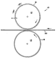
- The present invention will be more particularly described with reference to the accompanying drawing, the sole Figure of which illustrates a roll pass apparatus of the present invention.
- Broadly, in accordance with the invention, a grain-oriented silicon steel which has been cold rolled to final gauge sheet or
strip product 20 is passed through a roll pass or set 10 defined by ananvil roll 14 and ascribing roll 12, thescribing roll 12 having a roll surface with a plurality ofprojections 16 thereon as shown in the Figure. - The
anvil roll 14 is constructed, at least in part, from a material that is relatively more elastic than the material from which scribingroll 12 is constructed. Anvilroll 14 may be entirely constructed from such elastic material, preferably, however, at least the contact surface is provided as alayer 18 of relatively more elastic material. Whenroll 14 is provided with aseparate layer 18 of relatively elastic material, the remainder ofroll 14underlying layer 18 may be constructed of any of various materials to provide a suitable strong anvil core over which the relativelysofter anvil layer 18 is placed. The anvil core may be made of metals such as steel. Preferably, at least the contact surface comprised oflayer 18 is made of material having a relatively low shear modulus of elasticity. It is important that the contact surface ofanvil roll 14 be resilient enough to recover its original shape assheet 20 passes through roll set 10 between rotatingrolls - Scribing
roll 12 has a roll surface with a plurality ofprojections 16 thereon in a spaced-apart relation. Thescribing roll 12 may be constructed of a relatively inelastic material which is strong and hard and durable enough to withstand the compressive contact withstrip 20 as it passes throughroll set 10. Preferably, at least theprojections 16 onroll 12 are constructed of such material, such as steel. Theprojections 16 are spaced apart on the roll surface of scribingroll 12 and are adapted to impose a compressive deformation on the surface ofsteel strip 20.Projections 16 are generally transverse to the rolling direction and preferably are substantially perpendicular thereto. As shown in the Figure,projections 16 are arranged on the roll surface in a direction substantially parallel to the axes ofrolls Projections 16 may be of any of various shapes; however, it is preferred thatprojections 16 be generally triangular in cross section as shown in the Figure in order to narrowly define the area of compressive force or stress applied to the surface ofstrip 20. - As shown in the Figure,
projections 16 are spaced apart near the peaks a distance "a" which may be of the order of 2 to 10 mm in order to impose a compressive force or stress to the steel surface at intervals of about 2 to 10 mm. The width "b" of each projection as measured between the valleys defining a projection may be of the order of 2 to 10 mm. The depth "c" of the projections may be of the order of 0.5 to 10 mm. The particular dimensions and spacing of the scribing projections is important to achieving the desired magnetic improvement in the steel; however, it can be readily determined in the practice of the present invention. None of these dimensions of the projections are critical to the present invention. - The
roll set 10 comprised ofanvil roll 14 and scribingroll 12 may be generally freely-rotatable rolls which are caused to rotate about their axes by the movement ofstrip 20 passing therebetween. It is preferred that the rolls be rotated at a tangential velocity esentially equal to the velocity of thestrip 20 passing throughroll set 10. - As a specific example, a 0.26 mm final gauge and final texture annealed regular oriented silicon steel with Bs > 1.84 and core loss of .747 WPP at 1.7 Tesla, at 60 Hertz was used to demonstrate the advantage of an anvil roll made of a relatively elastic material of relatively low modulus of elasticity. The scribing roll was made of hard steel and the anvil of rubber having a durometer hardness of 80. The steel typically has a shear modulus of elasticity of 12 x 106 psi (8 x 1052 2 kg/cm2).
- Samples 30.5 cm long by 3 cm wide of the regular oriented silicon steel were placed between the anvil and scribing rolls and the rolls were adjusted until they just touched the subject sample. Then the subject sample was removed, and on successive samples, the scribing rolls were adjusted so that the opening between them was a various distances smaller than the thickness of the subject steel. These smaller distances are noted in the Table in the column headed Roll Gap Setting. A comparison set of samples was processed using an anvil of hard steel. The scribing roll had substantially triangular projections machined into a steel roll spaced at intervals of about 6 mm and accordingly were about 6 mm wide. The projections were about 4.8 mm deep. The steel was scribed to a depth of less than about 6 x 10⁻³ mm.

- In the Table, the "Change in 60 Hz Core Loss at 1.7 Tesla" is shown for the present invention and for a similar method using a steel anvil. The column entitled "Difference" indicates the decreased sensitivity to overscribing of a rubber anvil system compared to a hard anvil system. The "Difference" represents the difference in change in core loss between the steel samples scribed using a steel anvil and those scribed using a rubber anvil.
- It is clear that a steel anvil generally results in damage rather than improvement in the core loss, even forthe least intense scribing settings. This is believed to be because of the extreme sensitivity of the steel to the force of scribing and the extreme rigidity of a system employing a steel anvil. On the other hand, with a rubber anvil, reductions of as much as .022 WPP were achieved, an improvement of about 3%. The Table demonstrates that it is more dificult to impart a superficial disturbance with a steel anvil than with a rubber anvil. The softer anvil data indicates that core loss improvements can be obtained and may be optimized by adjustments in roller gap setting. The data further shows that it is not practical to use an anvil roll made of hard material, such as steel, for typically in practice, the final gauge or oriented silicon steel is not perfectly uniform and because of the extremely precise control required of the pressure exerted in order to avoid overscribing or underscribing. Underscribing is the case wherein little or no core loss improvement results. Overscribing is the case wherein the steel is damaged, resulting in core loss degradation. The final gauge may vary .0076 mm, for example, over the length and/or width of the steel sheet. It has been found that a more elastic material allows the steel to pass through a scribing roll set with significantly less possibility of overscribing the steel.
- By the use of a scribing roll and an anvil roll in accordance with the invention and specifically with the anvil roll being constructed from rubber and the scribing roll being constructed from steel, variations in the gauge of the flat-rolled steel product passing between the rolls will not significantly affect the depth of the scribes imparted to the steel. In this manner, uniform scribing may be obtained without varying the spacing between the rolls as the final gauge of the cold-rolled product passing therebetween may vary. As the speed at which the rolls may be rotated is not limited, the method of the invention may be used in line with any conventional processing equipment used in the production of grain-oriented silicon steel. In accordance with the examples herein, the scribing operation may be performed after final high temperature texture annealing at the exit end of a continuous operation, such as a heatflattening and coating line. It is contemplated that the present invention is also useful for scribing the the cold-rolled final gauge steel which has been decarburized but prior to final texture annealing. The roll set could be positioned in the continuous processing line after the decarburization annealing furnace. Furthermore, the extent or depth of scribing may be controlled as desired, depending upon when the scribing operation is performed in the continuous processing line and if the final texture annealed product will be stress relief annealed during subsequent fabrication.
- The present invention does not appear to be limited to a particular type of grain-oriented silicon steel, although the invention will achieve the most benefits on high permeability steels having a permeability at 10 Oersteds of more than 1840 and large grains of greater than 3.0 mm as well as on thin gauge regular oriented silicon steel of about 0.23 mm or less.
Claims (15)
Priority Applications (1)
| Application Number | Priority Date | Filing Date | Title |
|---|---|---|---|
| AT85305215T ATE60367T1 (en) | 1984-12-19 | 1985-07-23 | METHOD AND APPARATUS FOR REDUCING CORE LOSS OF CORNORATED SILICON STEEL. |
Applications Claiming Priority (2)
| Application Number | Priority Date | Filing Date | Title |
|---|---|---|---|
| US06/683,839 US4533409A (en) | 1984-12-19 | 1984-12-19 | Method and apparatus for reducing core losses of grain-oriented silicon steel |
| US683839 | 1984-12-19 |
Publications (3)
| Publication Number | Publication Date |
|---|---|
| EP0185437A2 EP0185437A2 (en) | 1986-06-25 |
| EP0185437A3 EP0185437A3 (en) | 1988-01-07 |
| EP0185437B1 true EP0185437B1 (en) | 1991-01-23 |
Family
ID=24745657
Family Applications (1)
| Application Number | Title | Priority Date | Filing Date |
|---|---|---|---|
| EP85305215A Expired - Lifetime EP0185437B1 (en) | 1984-12-19 | 1985-07-23 | Method and apparatus for reducing core losses of grain-oriented silicon steel |
Country Status (6)
| Country | Link |
|---|---|
| US (1) | US4533409A (en) |
| EP (1) | EP0185437B1 (en) |
| JP (1) | JPS61149433A (en) |
| KR (1) | KR900006689B1 (en) |
| AT (1) | ATE60367T1 (en) |
| DE (1) | DE3581513D1 (en) |
Families Citing this family (19)
| Publication number | Priority date | Publication date | Assignee | Title |
|---|---|---|---|---|
| JPS61117218A (en) * | 1984-11-10 | 1986-06-04 | Nippon Steel Corp | Manufacture of grain oriented magnetic steel sheet of low iron loss |
| DE3675325D1 (en) * | 1985-10-14 | 1990-12-06 | Nippon Steel Corp | COLD-FASTENING DEVICE. |
| US4897131A (en) * | 1985-12-06 | 1990-01-30 | Nippon Steel Corporation | Grain-oriented electrical steel sheet having improved glass film properties and low watt loss |
| GB2208871B (en) * | 1987-08-22 | 1991-03-27 | British Steel Plc | Processing grain-oriented "electrical" steel |
| US5223048A (en) * | 1988-10-26 | 1993-06-29 | Kawasaki Steel Corporation | Low iron loss grain oriented silicon steel sheets and method of producing the same |
| US5123977A (en) * | 1989-07-19 | 1992-06-23 | Allegheny Ludlum Corporation | Method and apparatus for refining the domain structure of electrical steels by local hot deformation and product thereof |
| JPH0723511B2 (en) * | 1989-12-07 | 1995-03-15 | 新日本製鐵株式会社 | Unidirectional electromagnetic steel strip processing equipment |
| US5211771A (en) * | 1991-03-13 | 1993-05-18 | Nisshin Steel Company, Ltd. | Soft magnetic alloy material |
| JPH05247538A (en) * | 1991-11-29 | 1993-09-24 | Nippon Steel Corp | Manufacture of low iron loss grain-oriented electrical steel sheet |
| KR940011651A (en) * | 1992-11-17 | 1994-06-21 | 존 디. 왈턴 | Flat scribing roller for refining magnetic domain structure of electric steel by local mechanical deformation |
| US5350464A (en) * | 1992-11-17 | 1994-09-27 | Allegheny Ludlum Corporation | Silicon steel strip having mechanically refined magnetic domain wall spacings and method for producing the same |
| KR940011648A (en) * | 1992-11-17 | 1994-06-21 | 존 디. 왈턴 | Fan anvil roller for refining magnetic domain structure of electric steel |
| US5312496A (en) * | 1992-11-17 | 1994-05-17 | Allegheny Ludlum Corporation | Skin pass rolling of mechanically scribed silicon steel |
| US5408856A (en) * | 1992-11-17 | 1995-04-25 | Allegheny Ludlum Corporation | Apparatus for domain refining electrical steels by local mechanical deformation with multiple scribing rolls |
| US5588321A (en) * | 1995-01-25 | 1996-12-31 | Allegheny Ludlum Corporation | Segmented scribing roller for refining the domain structure of electrical steels by local mechanical deformation |
| EP0837148B1 (en) * | 1996-10-21 | 2001-08-29 | Kawasaki Steel Corporation | Grain-oriented electromagnetic steel sheet |
| US10814451B2 (en) * | 2016-02-12 | 2020-10-27 | Darex, Llc | Powered sharpener with controlled deflection of flexible abrasive member |
| US9914193B2 (en) * | 2016-02-12 | 2018-03-13 | Darex, Llc | Powered sharpener with cold forging member |
| CN114480792B (en) * | 2021-12-15 | 2023-06-20 | 中南大学 | Method for regulating and controlling crystal face orientation of metal material, obtained metal material and application thereof |
Family Cites Families (19)
| Publication number | Priority date | Publication date | Assignee | Title |
|---|---|---|---|---|
| US1313054A (en) * | 1919-08-12 | Arthur francis berry | ||
| DE626673C (en) * | 1932-02-13 | 1936-07-01 | Hoesch Koeln Neuessen Akt Ges | Process and device for the production of coarse-grained, recrystallized strips or sheets |
| US2234968A (en) * | 1938-11-12 | 1941-03-18 | American Rolling Mill Co | Art of reducing magnetostrictive effects in magnetic materials |
| DE1804208B1 (en) * | 1968-10-17 | 1970-11-12 | Mannesmann Ag | Process for reducing the watt losses of grain-oriented electrical steel sheets, in particular of cube-texture sheets |
| US3673838A (en) * | 1970-01-29 | 1972-07-04 | Brownbuilt Ltd | Continuous forming of transverse stiffening ribs on strip material |
| JPS5410922B2 (en) * | 1972-12-19 | 1979-05-10 | ||
| JPS5423647B2 (en) * | 1974-04-25 | 1979-08-15 | ||
| JPS53129116A (en) * | 1977-04-18 | 1978-11-10 | Nippon Steel Corp | Oriented electromagnetic steel sheet with excellent magnetic characteristic s |
| JPS585968B2 (en) * | 1977-05-04 | 1983-02-02 | 新日本製鐵株式会社 | Manufacturing method of ultra-low iron loss unidirectional electrical steel sheet |
| JPS58747B2 (en) * | 1978-07-04 | 1983-01-07 | 新日本製鐵株式会社 | Low iron loss unidirectional silicon steel sheet and its manufacturing method |
| JPS6014827B2 (en) * | 1980-03-14 | 1985-04-16 | 新日本製鐵株式会社 | Low core loss unidirectional electrical steel sheet and its manufacturing method |
| JPS5855211B2 (en) * | 1980-09-02 | 1983-12-08 | 新日本製鐵株式会社 | (h,k,o) Manufacturing method for unidirectional electrical steel sheet with crystals in [001] orientation and excellent iron loss |
| JPS5833296B2 (en) * | 1980-10-24 | 1983-07-19 | 川崎製鉄株式会社 | Manufacturing method of low iron loss, grain-oriented silicon steel sheet |
| BE893861A (en) * | 1981-07-17 | 1982-11-16 | Nippon Steel Corp | METHOD AND APPARATUS FOR REDUCING THE ACTIVE LOSS OF AN ELECTROMAGNETIC STEEL SHEET AND SHEET OBTAINED |
| JPS5847535A (en) * | 1981-09-18 | 1983-03-19 | Sanko Kuki Sochi Kk | Recessed mark working of welded pipe material |
| CA1197759A (en) * | 1982-07-19 | 1985-12-10 | Robert F. Miller | Method for producing cube-on-edge silicon steel |
| JPS59197520A (en) * | 1983-04-20 | 1984-11-09 | Kawasaki Steel Corp | Manufacture of single-oriented electromagnetic steel sheet having low iron loss |
| JPS6096719A (en) * | 1983-10-31 | 1985-05-30 | Kawasaki Steel Corp | Apparatus for decreasing iron loss of directional silicon steel sheet |
| JPS61139624A (en) * | 1984-12-13 | 1986-06-26 | Kawasaki Steel Corp | Production of unidirectional silicon steel sheet having very high magnetic flux density and small iron loss |
-
1984
- 1984-12-19 US US06/683,839 patent/US4533409A/en not_active Expired - Fee Related
-
1985
- 1985-07-23 EP EP85305215A patent/EP0185437B1/en not_active Expired - Lifetime
- 1985-07-23 AT AT85305215T patent/ATE60367T1/en not_active IP Right Cessation
- 1985-07-23 DE DE8585305215T patent/DE3581513D1/en not_active Expired - Fee Related
- 1985-07-26 KR KR1019850005369A patent/KR900006689B1/en not_active IP Right Cessation
- 1985-08-05 JP JP60172241A patent/JPS61149433A/en active Granted
Also Published As
| Publication number | Publication date |
|---|---|
| US4533409A (en) | 1985-08-06 |
| JPS61149433A (en) | 1986-07-08 |
| KR860005039A (en) | 1986-07-16 |
| EP0185437A2 (en) | 1986-06-25 |
| KR900006689B1 (en) | 1990-09-17 |
| ATE60367T1 (en) | 1991-02-15 |
| EP0185437A3 (en) | 1988-01-07 |
| JPH0525929B2 (en) | 1993-04-14 |
| DE3581513D1 (en) | 1991-02-28 |
Similar Documents
| Publication | Publication Date | Title |
|---|---|---|
| EP0185437B1 (en) | Method and apparatus for reducing core losses of grain-oriented silicon steel | |
| US4711113A (en) | Apparatus for reducing core losses of grain-oriented silicon steel | |
| DE68925743T2 (en) | Process for producing grain-oriented electrical sheets by rapid heating | |
| US5123977A (en) | Method and apparatus for refining the domain structure of electrical steels by local hot deformation and product thereof | |
| EP0662520A1 (en) | Low-iron-loss grain-oriented electromagnetic steel sheet and method of producing the same | |
| CN111394615B (en) | Medical high-performance TA3G pure titanium plate and preparation method thereof | |
| US5080326A (en) | Method and apparatus for refining the domain structure of electrical steels by local hot deformation and product thereof | |
| EP0225619B1 (en) | Grain-oriented electrical steel sheet having improved glass film properties and low watt loss and a process for producing same | |
| US3415696A (en) | Process of producing silicon steel laminations having a very large grain size after final anneal | |
| US4680062A (en) | Method for reducing core losses of grain-oriented silicon steel using liquid jet scribing | |
| EP0432732A2 (en) | Thermal flattening semi-processed electrical steel | |
| US5350464A (en) | Silicon steel strip having mechanically refined magnetic domain wall spacings and method for producing the same | |
| ATE343651T1 (en) | METHOD FOR PRODUCING NON-CORNORIENTED ELECTRICAL SHEET AND SHEETS PRODUCED BY SUCH PROCESS | |
| EP0143548A1 (en) | Grain-oriented silicon steel sheet having a low iron loss free from deterioration due to stress-relief annealing and a method of producing the same | |
| EP0323155A1 (en) | Method for producing low iron loss grain oriented silicon steel sheets | |
| JPH07320921A (en) | Directional electromagnetic steel sheet at low iron loss | |
| US4737203A (en) | Method for reducing core losses of grain-oriented silicon steel using liquid jet scribing | |
| JP3504283B2 (en) | Manufacturing method of grain-oriented electrical steel sheet with extremely low iron loss | |
| JPH01156426A (en) | Manufacture of directional magnetic steel plate having low iron loss | |
| US5041170A (en) | Method employing skin-pass rolling to enhance the quality of phosphorus-striped silicon steel | |
| CA1078292A (en) | Method of producing ferritic stainless steel for coinage | |
| JPH01159323A (en) | Iron loss decreasing device for grain oriented electrical steel sheet | |
| KR900006691B1 (en) | Making process for si plate | |
| SU653302A1 (en) | Method of obtaining electrical steel | |
| JPH02101121A (en) | Manufacture of grain-oriented silicon steel sheet |
Legal Events
| Date | Code | Title | Description |
|---|---|---|---|
| PUAI | Public reference made under article 153(3) epc to a published international application that has entered the european phase |
Free format text: ORIGINAL CODE: 0009012 |
|
| AK | Designated contracting states |
Kind code of ref document: A2 Designated state(s): AT BE DE FR GB IT SE |
|
| PUAL | Search report despatched |
Free format text: ORIGINAL CODE: 0009013 |
|
| AK | Designated contracting states |
Kind code of ref document: A3 Designated state(s): AT BE DE FR GB IT SE |
|
| 17P | Request for examination filed |
Effective date: 19880706 |
|
| 17Q | First examination report despatched |
Effective date: 19891024 |
|
| ITF | It: translation for a ep patent filed |
Owner name: FIAMMENGHI - DOMENIGHETTI |
|
| GRAA | (expected) grant |
Free format text: ORIGINAL CODE: 0009210 |
|
| AK | Designated contracting states |
Kind code of ref document: B1 Designated state(s): AT BE DE FR GB IT SE |
|
| PG25 | Lapsed in a contracting state [announced via postgrant information from national office to epo] |
Ref country code: BE Effective date: 19910123 Ref country code: AT Effective date: 19910123 |
|
| REF | Corresponds to: |
Ref document number: 60367 Country of ref document: AT Date of ref document: 19910215 Kind code of ref document: T |
|
| REF | Corresponds to: |
Ref document number: 3581513 Country of ref document: DE Date of ref document: 19910228 |
|
| ET | Fr: translation filed | ||
| ITPR | It: changes in ownership of a european patent |
Owner name: CAMBIO RAGIONE SOCIALE;ALLEGHENY LUDLUM CORPORATIO |
|
| PLBE | No opposition filed within time limit |
Free format text: ORIGINAL CODE: 0009261 |
|
| STAA | Information on the status of an ep patent application or granted ep patent |
Free format text: STATUS: NO OPPOSITION FILED WITHIN TIME LIMIT |
|
| 26N | No opposition filed | ||
| PGFP | Annual fee paid to national office [announced via postgrant information from national office to epo] |
Ref country code: SE Payment date: 19920615 Year of fee payment: 8 |
|
| PG25 | Lapsed in a contracting state [announced via postgrant information from national office to epo] |
Ref country code: SE Effective date: 19930724 |
|
| PGFP | Annual fee paid to national office [announced via postgrant information from national office to epo] |
Ref country code: FR Payment date: 19940613 Year of fee payment: 10 |
|
| PGFP | Annual fee paid to national office [announced via postgrant information from national office to epo] |
Ref country code: GB Payment date: 19940620 Year of fee payment: 10 |
|
| PGFP | Annual fee paid to national office [announced via postgrant information from national office to epo] |
Ref country code: DE Payment date: 19940623 Year of fee payment: 10 |
|
| EUG | Se: european patent has lapsed |
Ref document number: 85305215.7 Effective date: 19940210 |
|
| PG25 | Lapsed in a contracting state [announced via postgrant information from national office to epo] |
Ref country code: GB Effective date: 19950723 |
|
| GBPC | Gb: european patent ceased through non-payment of renewal fee |
Effective date: 19950723 |
|
| PG25 | Lapsed in a contracting state [announced via postgrant information from national office to epo] |
Ref country code: DE Effective date: 19960402 |
|
| PG25 | Lapsed in a contracting state [announced via postgrant information from national office to epo] |
Ref country code: FR Effective date: 19960430 |
|
| REG | Reference to a national code |
Ref country code: FR Ref legal event code: ST |
|
| REG | Reference to a national code |
Ref country code: FR Ref legal event code: ST |
|
| REG | Reference to a national code |
Ref country code: FR Ref legal event code: ST |