EP0185428A1 - Robinet à boule fabriqué entièrement en matériau plastique - Google Patents
Robinet à boule fabriqué entièrement en matériau plastique Download PDFInfo
- Publication number
- EP0185428A1 EP0185428A1 EP19850202079 EP85202079A EP0185428A1 EP 0185428 A1 EP0185428 A1 EP 0185428A1 EP 19850202079 EP19850202079 EP 19850202079 EP 85202079 A EP85202079 A EP 85202079A EP 0185428 A1 EP0185428 A1 EP 0185428A1
- Authority
- EP
- European Patent Office
- Prior art keywords
- casing
- ball
- spindle
- ball valve
- valve according
- Prior art date
- Legal status (The legal status is an assumption and is not a legal conclusion. Google has not performed a legal analysis and makes no representation as to the accuracy of the status listed.)
- Granted
Links
Images


Classifications
-
- F—MECHANICAL ENGINEERING; LIGHTING; HEATING; WEAPONS; BLASTING
- F16—ENGINEERING ELEMENTS AND UNITS; GENERAL MEASURES FOR PRODUCING AND MAINTAINING EFFECTIVE FUNCTIONING OF MACHINES OR INSTALLATIONS; THERMAL INSULATION IN GENERAL
- F16K—VALVES; TAPS; COCKS; ACTUATING-FLOATS; DEVICES FOR VENTING OR AERATING
- F16K27/00—Construction of housing; Use of materials therefor
- F16K27/06—Construction of housing; Use of materials therefor of taps or cocks
- F16K27/067—Construction of housing; Use of materials therefor of taps or cocks with spherical plugs
-
- F—MECHANICAL ENGINEERING; LIGHTING; HEATING; WEAPONS; BLASTING
- F16—ENGINEERING ELEMENTS AND UNITS; GENERAL MEASURES FOR PRODUCING AND MAINTAINING EFFECTIVE FUNCTIONING OF MACHINES OR INSTALLATIONS; THERMAL INSULATION IN GENERAL
- F16K—VALVES; TAPS; COCKS; ACTUATING-FLOATS; DEVICES FOR VENTING OR AERATING
- F16K5/00—Plug valves; Taps or cocks comprising only cut-off apparatus having at least one of the sealing faces shaped as a more or less complete surface of a solid of revolution, the opening and closing movement being predominantly rotary
- F16K5/06—Plug valves; Taps or cocks comprising only cut-off apparatus having at least one of the sealing faces shaped as a more or less complete surface of a solid of revolution, the opening and closing movement being predominantly rotary with plugs having spherical surfaces; Packings therefor
-
- Y—GENERAL TAGGING OF NEW TECHNOLOGICAL DEVELOPMENTS; GENERAL TAGGING OF CROSS-SECTIONAL TECHNOLOGIES SPANNING OVER SEVERAL SECTIONS OF THE IPC; TECHNICAL SUBJECTS COVERED BY FORMER USPC CROSS-REFERENCE ART COLLECTIONS [XRACs] AND DIGESTS
- Y10—TECHNICAL SUBJECTS COVERED BY FORMER USPC
- Y10T—TECHNICAL SUBJECTS COVERED BY FORMER US CLASSIFICATION
- Y10T137/00—Fluid handling
- Y10T137/7504—Removable valve head and seat unit
Definitions
- the present invention relates to a ball valve which is made entirely of plastics material and comprises a tubular casing with connection pieces which are fastened to both its ends and which together form a through passage for a medium, a ball disposed in the through passage inside the casing and provided with a through opening, an operating means formed by a spindle inserted into an opening in the casing, cooperating with the ball, and provided with an operating grip to enable the ball to be turned so as to close or open the through passage.
- Ball valves of this kind are intended to be installed in underground polyehtylene pipes, and must on the one hand function reliably and on the other hand be resistant to the penetration of dirt and moisture.
- each of the connection pipes is usually provided with a seat for the valve and is fastened to the casing by butt welding.
- the seats are axially displaced and moved towards one another.
- the problem thus arising is that the axial displacement during the butt welding must be such that on completion of the welding the ball is correctly enclosed between the seats.
- This procedure requires on the one hand accurate dimensioning and machining of the component parts which are to be welded together, and on the other hand a very accurately conducted welding process.
- changes may be caused by thermal expansion and contraction, so that the ball will no longer be enclosed under the correct pressure between the seats.
- the present invention seeks to provide a ball valve which is entirely made of plastics material and which complies with requirements for underground installation, while the abovementioned disadvantages are avoided.
- a further object of the invention is to provide a ball valve which is economical to produce and has the smallest possible number of components, and in which these components can be assembled in a simple manner.
- the casing consists of a substantially cylindrical outer casing to each end of which the connection pieces are welded, and of an inner casing which is disposed therein and is constructed of two parts, each of which has a seat and which enclose the ball between them, the inner casing being provided at each end with an external cylindrical surface projecting out of the outer casing, each such surface cooperating with an internal cylindrical surface on the two connection pieces in order to form a guide for these connection pieces.
- the two parts of the inner casing are joined together by screwthreads and are each provided with an external cylindrical guide surface for the connection pieces.
- connection pieces Since the ball is enclosed between the two parts of the inner casing, which are joined together by screwthreads, the pressure under which the ball is enclosed can be adjusted accurately. During the welding of the connection pieces to the outer casing, the connection pieces can be displaced in the axial direction, relative to the inner casing, over the guide surfaces of the inner casing, so that a good, reliable weld can be made without affecting the installation of the ball.
- the inner casing is preferably fastened relative to the outer casing with the aid of the spindle of the operating means, this spindle being provided with a neck in the region lying, in the installed position, at the boundary between the outer and inner casings, while a space is left free between the inner and outer casings in the region where the spindle of the operating means passes into the casing, so that a retaining plate can be inserted between the inner and outer casings, this retaining plate engaging in the neck of the spindle in order to secure the latter in the axial direction.
- valve according to the invention can be installed in a simple manner because, once the ball is enclosed between the two parts of the inner casing, this inner casing is placed in the outer casing, the spindle of the operating means is then pushed inwards from the outer periphery of the outer casing until it engages in the ball, the spindle then being fastened by means of the retaining plate.
- the two connection pieces can thereupon be welded to the outer casing.
- annular ridge is formed around the opening in the casing through which the spindle of the operating means is passlj, thus forming a guide for this spindle, and a second annular ridge is formed concentrically to and at a distance from this guide ridge, the outer surface of this second ridge cooperating with an internal surface, in contact with it, of the operating grip forming an integral part of the spindle.
- the operating grip and the spindle are made in one piece, for example by injection moulding.
- the operating grip is provided at its bottom edge with a widened portion having an internal cylindrical surface cooperating with an external cylindrical surface of the second ridge.
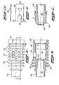
- the ball valve according to the invention consists of a tubular outer casing 1, to each end of which a connection piece 2, 3 is welded by a butt weld 4, 4'.
- an inner casing 5 consisting of a first part 5a and a screw-in member 5b which can be screwed in the first part by means of a screwthread 6.
- the two parts of the inner casing are sealed relative to one another by means of an 0-ring 7.
- a ball 8 which is provided with a through opening 9.
- the ball 8 is enclosed between seats 10a and 10b and is sealed in relation to the inner casing by means of 0-rings 11, 11'.
- the inner casing projects out of the outer casing on both sides, and at each end is provided with an external cylindrical surface 12a and 12b respectively. These surfaces cooperate with internal cylindrical surfaces 13 and 14 respectively on the connection pieces 2 and 3, the surfaces being sealed relative to one another by means of 0-rings 15, 15'.
- the ball 8 enclosed in the casing 5 can be turned with the aid of an operating means 16 consisting of a spindle 17 and an operating grip 18.
- the spindle 17 extends through an opening 19 in the outer casing and an opening 20, in alignment therewith, in the inner casing, and at its end has a projection 21 of rectangular cross-section engaging in a correspondingly shaped recess in the ball (see fig. 7).
- the first part 5a of the inner casing 5 is mainly in the form of a hollow cylinder, this inner casing being adapted to fit into the outer casing.
- the internal passage in the part 5a consists of a first slightly convergent inlet portion 22 which leads via the seat 10a into a chamber 23 for the ball.
- the chamber 23 is provided at the end opposite the seat 10a with a screwthread 6 enabling the screw-in member 5b shown in fig. 4 to be screwed into it.
- the screw-in member 5b is provided with a passage 24 which is slightly divergent from the seat 10b.
- the inner casing, together with the ball 8 placed in the chamber 23 has a passage 22, 9, 24 for the medium.
- this passage is directly connected to the interior of the respective connection pieces 2 and 3.
- the outer periphery of the part 5a is provided with a number of ribs 25 which extend around it and which are regularly spaced apart. These ribs ensure a light construction and uniform thickness of the wall of the inner casing.
- the opening 20 through which the spindle 17 of the operating means 16 can be passed in order to turn the ball 8.
- the outer surface of the part 5a is provided with a flat surface 26, the purpose of which will be explained later on.
- the substantially tubular outer casing 1 shown in figs. 5 and 6 is provided with the opening 19, which in the assembled state of the valve lines up with the opening 20 in the part 5a of the inner casing.
- the interior surface of the outer casing is provided in the region of the opening 19 with a recess 27, which in the assembled state leaves free, in conjunction with the flat surface 26 of the inner casing, a space into which a retaining plate 28 can be inserted, this retaining plate being shown in figs. 9 and 10.
- Around the opening 19 is provided on the outer periphery of the outer casing an annular ridge 29 which serves to guide the spindle 17 of the operating means 16.
- a second annular ridge 30, concentric thereto, is disposed and is provided on its outer periphery with regularly spaced teeth 31.
- stiffening ribs 32, 33 are disposed between the ridges 29 and 30.
- the operating means 16 shown in fig. 7 is in the form of an integral injection moulding consisting of the spindle 17 and the operating grip 18.
- the spindle 17 is provided with a neck 34, which in the assembled state of the operating means is situated in the free space which, as described above, is formed by the flat surface 26 of the inner casing and the recess 27 in the outer casing.
- the retaining plate 28 is provided at one end with an open slot 35, the width of which corresponds approximately to the diameter of the neck 34 of the spindle 17.
- the retaining plate inserted into the space 26, 27 can thus engage by means of lips 36, 37 lying one on each side of the slot 35 in the neck 34 of spindle 17, so that the spindle can be secured in the axial direction.
- the retaining plate 28 is in addition provided with a spring lip or boss 38 which, as illustrated in fig. 1, forms a snap connection with a cavity 39 formed between two adjoining ribs 25 in the flat surface 26 of the inner casing.
- a spring lip or boss 38 Beneath the neck 34 the spindle 17 is provided with a second neck 40, which serves to receive an 0-ring 41 effecting the sealing between the spindle 17 and the part 5a of the inner casing.
- the operating grip 18 of the operating means 16 has a square cross-section, so that a tool can easily act on it to operate the valve.
- the grip 18 merges near its lower face, via a horizontal portion 42, into a cylindrical wall 43.
- the inside diameter of the wall 43 corresponds approximately to the outside diameter of the ridge 30, while the inside of the wall 43 is provided with teeth 44 adapted to cooperate with the teeth 31 on the ridge 30.
- the teeth 44 and 31 are so shaped that both in the completely opened position and in the closed position, after turning 90°, they interengage without causing stresses in the wall 43.
- the minimum torque during the turning of the operating means should be constant.
- the number and the shape of the teeth can be modified, provided that it is ensured that in the closed and open positions the teeth fully interengage.
- the quotient 90° : ⁇ should give a whole even number.
- a number of projections 45, 45' which in conjunction with the ribs 32 and 33 permit the turning of the operating means over an angle of 90°.
- the teeth 44 run over the teeth 31, so that stresses are produced in the wall 43.
- the teeth engage fully in one another and the wall 43 is free of stress. Since the wall 43 lies against the ridge 30, appropriate sealing is likewise achieved between the operating grip and the outer casing, so that no dirt and/or moisture can penetrate to the inside.
- connection piece 2 shown in fig. 8.
- This connection piece consists of a tubular portion 46 which at one end widens into a cylindrical wall 47 whose circumference measurements coincide with those of the ends of the outer casing 1.
- the interior surface 13 of the tubular portion 16 has approximately the same diameter as the outside cylindrical surface 12a of the part 5a of the inner casing 5.
- connection piece For the butt welding, the surfaces which are to be welded together are first heated and then pressed against one another with a determined pressure. During this welding there is thus an axial displacement of the connection piece in relation to the inner casing.
- the construction according to the invention makes this displacement possible without affecting the action of the valve, so that a good, reliable weld can always be achieved.
- connection piece and the outer casing are made of the same material as the pipe in which the valve is to be inserted, that is to say polyehtylene.
- the other components of the valve such as the operating means, the inner casing, the ball and the retaining plate, are preferably made of a higher grade material, such as technical plastics.
- a ball valve which consists of relatively few components and is easily assembled since on the one hand the ball is entirely enclosed in the innner casing and on the other hand the operating means can be inserted into the casing from the outer periphery and can be fastened in a simple manner by the retaining plate.
- the connection pieces it is possible for the connection pieces to be welded in a reliable manner without affecting the working of the valve.
- the other casing may be in the form of an integral injection moulding incorporating one of the connection pieces, so that after the installation of the inner casing and the operating means it will only be necessary to fasten the other connection piece by butt welding.
- the retaining plate 28 may also have a tubular shape, in which case the outer surface of the part 5a (in fig. 3 at the right) has a smaller diameter in order to let free an annular space in between the inner and outer casing for inserting said tubular retaining plate.
Landscapes
- Engineering & Computer Science (AREA)
- General Engineering & Computer Science (AREA)
- Mechanical Engineering (AREA)
- Valve Housings (AREA)
- Taps Or Cocks (AREA)
- Multiple-Way Valves (AREA)
Priority Applications (1)
| Application Number | Priority Date | Filing Date | Title |
|---|---|---|---|
| AT85202079T ATE34439T1 (de) | 1984-12-17 | 1985-12-13 | Kugelventil ganz aus plastischem material hergestellt. |
Applications Claiming Priority (2)
| Application Number | Priority Date | Filing Date | Title |
|---|---|---|---|
| NL8403825A NL8403825A (nl) | 1984-12-17 | 1984-12-17 | Kogelafsluiter die geheel is vervaardigd uit kunststof. |
| NL8403825 | 1984-12-17 |
Publications (2)
| Publication Number | Publication Date |
|---|---|
| EP0185428A1 true EP0185428A1 (fr) | 1986-06-25 |
| EP0185428B1 EP0185428B1 (fr) | 1988-05-18 |
Family
ID=19844923
Family Applications (1)
| Application Number | Title | Priority Date | Filing Date |
|---|---|---|---|
| EP85202079A Expired EP0185428B1 (fr) | 1984-12-17 | 1985-12-13 | Robinet à boule fabriqué entièrement en matériau plastique |
Country Status (5)
| Country | Link |
|---|---|
| US (1) | US4697787A (fr) |
| EP (1) | EP0185428B1 (fr) |
| AT (1) | ATE34439T1 (fr) |
| DE (1) | DE3562811D1 (fr) |
| NL (1) | NL8403825A (fr) |
Cited By (4)
| Publication number | Priority date | Publication date | Assignee | Title |
|---|---|---|---|---|
| GB2205630A (en) * | 1987-06-08 | 1988-12-14 | Antony Waterfield | Base unit and valve for underground water supply chamber |
| EP0534111A1 (fr) * | 1991-09-13 | 1993-03-31 | Georg Fischer Rohrleitungssysteme AG | Robinet à membrane en plastique et son utilisation |
| EP0623770A1 (fr) * | 1993-05-04 | 1994-11-09 | Nefit Industrial B.V. | Robinet à tournant spherique |
| CN112005036A (zh) * | 2018-05-28 | 2020-11-27 | 株式会社不二工机 | 流路切换阀及其制造方法 |
Families Citing this family (10)
| Publication number | Priority date | Publication date | Assignee | Title |
|---|---|---|---|---|
| NL9000772A (nl) * | 1990-04-02 | 1991-11-01 | Nefit Nv | Kogelkraan. |
| US5085244A (en) * | 1991-03-14 | 1992-02-04 | Funk Douglas H | Assembly for cleaning a drain conduit |
| US5246203A (en) * | 1992-06-29 | 1993-09-21 | M&M Supply Co. | Oilfield valve |
| US5397101A (en) * | 1994-05-20 | 1995-03-14 | Perfection Corporation | Ball valve |
| US6176265B1 (en) * | 1995-11-14 | 2001-01-23 | Kiyoshi Takahashi | Valve unit having an insert molded inner valve block |
| DE19711740C2 (de) * | 1997-03-20 | 2000-11-30 | Stuebbe Asv Gmbh | Kugelhahn aus Kunststoff |
| WO2000046532A1 (fr) * | 1999-02-03 | 2000-08-10 | Teco Energy, Inc. | Appareil de raccordement de vanne resistant a l'erosion pour ecoulements de fluide corrosif a haute pression |
| US7350765B2 (en) * | 2005-07-06 | 2008-04-01 | Hydril Company Lp | Double-stop floating ball valve |
| DE102007028516A1 (de) * | 2007-06-21 | 2008-12-24 | Robert Bosch Gmbh | Magnetventil |
| CN101839353B (zh) * | 2010-05-13 | 2012-01-04 | 宁波日月制冷设备有限公司 | 球阀 |
Citations (3)
| Publication number | Priority date | Publication date | Assignee | Title |
|---|---|---|---|---|
| FR2324960A1 (fr) * | 1975-09-17 | 1977-04-15 | Rockwell International Corp | Robinet perfectionne a tournant spherique. |
| EP0051214A1 (fr) * | 1980-10-31 | 1982-05-12 | Bruno Tubaro | Robinet à boisseau |
| US4458878A (en) * | 1981-03-31 | 1984-07-10 | Asahi Yukizai Kogyo Co., Ltd. | Ball valve assembly |
Family Cites Families (19)
| Publication number | Priority date | Publication date | Assignee | Title |
|---|---|---|---|---|
| US221288A (en) * | 1879-11-04 | Improvement in cocks | ||
| US1381873A (en) * | 1919-10-30 | 1921-06-14 | Maurice D Larkin | Nozzle |
| US2741452A (en) * | 1952-06-05 | 1956-04-10 | Harshaw Chem Corp | Rotary plug valve retaining means |
| US3323542A (en) * | 1961-09-18 | 1967-06-06 | Crane Co | Fabricated ball valve |
| US3339887A (en) * | 1965-01-28 | 1967-09-05 | Fisher Governor Co | Balanced ball valve having pressure reducing flow ring |
| US3529621A (en) * | 1967-10-04 | 1970-09-22 | Young Stephen A | Integral stop construction for plumbing fitting |
| US3732885A (en) * | 1971-09-29 | 1973-05-15 | H Allen | Valve and method of assembling same |
| US4022427A (en) * | 1974-08-05 | 1977-05-10 | Dresser Industries, Inc. | Sleeve valve mandrel and seal means for indexing valve assembly |
| US4147184A (en) * | 1975-04-30 | 1979-04-03 | Baxter Travenol Laboratories, Inc. | Adjustable valve |
| US4023773A (en) * | 1976-01-28 | 1977-05-17 | Georg Fischer Aktiengesellschaft | True union ball valve |
| US4099705A (en) * | 1976-08-19 | 1978-07-11 | Celanese Corporation | End entry ball valve with seal wear compensation and force isolated seal |
| US4146055A (en) * | 1977-03-21 | 1979-03-27 | Ryder International Corporation | Valve structure |
| US4277046A (en) * | 1978-09-25 | 1981-07-07 | Cavileer Watson V | Irrigation valve |
| JPS6014063Y2 (ja) * | 1980-03-31 | 1985-05-04 | 積水化学工業株式会社 | 合成樹脂バルブ |
| US4465092A (en) * | 1980-10-16 | 1984-08-14 | Steven Vitale | Valve with anti-removal feature |
| US4523740A (en) * | 1981-10-01 | 1985-06-18 | Hayward Industries | Rotatable unitary ball valve |
| US4511120A (en) * | 1983-03-11 | 1985-04-16 | Kerotest Manufacturing Corp. | Plastic service valve |
| JPS59205079A (ja) * | 1983-05-04 | 1984-11-20 | Toyo Kako Kk | 樹脂製バルブ及びその製造方法 |
| US4617957A (en) * | 1983-07-25 | 1986-10-21 | Xomox Corporation | Rotary plug valve |
-
1984
- 1984-12-17 NL NL8403825A patent/NL8403825A/nl not_active Application Discontinuation
-
1985
- 1985-12-13 AT AT85202079T patent/ATE34439T1/de not_active IP Right Cessation
- 1985-12-13 EP EP85202079A patent/EP0185428B1/fr not_active Expired
- 1985-12-13 DE DE8585202079T patent/DE3562811D1/de not_active Expired
- 1985-12-17 US US06/809,902 patent/US4697787A/en not_active Expired - Fee Related
Patent Citations (3)
| Publication number | Priority date | Publication date | Assignee | Title |
|---|---|---|---|---|
| FR2324960A1 (fr) * | 1975-09-17 | 1977-04-15 | Rockwell International Corp | Robinet perfectionne a tournant spherique. |
| EP0051214A1 (fr) * | 1980-10-31 | 1982-05-12 | Bruno Tubaro | Robinet à boisseau |
| US4458878A (en) * | 1981-03-31 | 1984-07-10 | Asahi Yukizai Kogyo Co., Ltd. | Ball valve assembly |
Cited By (5)
| Publication number | Priority date | Publication date | Assignee | Title |
|---|---|---|---|---|
| GB2205630A (en) * | 1987-06-08 | 1988-12-14 | Antony Waterfield | Base unit and valve for underground water supply chamber |
| EP0534111A1 (fr) * | 1991-09-13 | 1993-03-31 | Georg Fischer Rohrleitungssysteme AG | Robinet à membrane en plastique et son utilisation |
| EP0623770A1 (fr) * | 1993-05-04 | 1994-11-09 | Nefit Industrial B.V. | Robinet à tournant spherique |
| NL9300749A (nl) * | 1993-05-04 | 1994-12-01 | Nefit Ind Bv | Kogelkraan. |
| CN112005036A (zh) * | 2018-05-28 | 2020-11-27 | 株式会社不二工机 | 流路切换阀及其制造方法 |
Also Published As
| Publication number | Publication date |
|---|---|
| NL8403825A (nl) | 1986-07-16 |
| DE3562811D1 (en) | 1988-06-23 |
| US4697787A (en) | 1987-10-06 |
| ATE34439T1 (de) | 1988-06-15 |
| EP0185428B1 (fr) | 1988-05-18 |
Similar Documents
| Publication | Publication Date | Title |
|---|---|---|
| US4697787A (en) | Ball valve made entirely of plastics material | |
| US5345964A (en) | Pipe piercing fitting and valve | |
| US5577529A (en) | Tapping fittings | |
| US4655480A (en) | Molded tapping member formed of a weldable plastics material | |
| US4032177A (en) | Compression fitting with tubing reinforcing insert | |
| JP2803383B2 (ja) | 高圧流体用継手 | |
| US5603530A (en) | Grab rings | |
| US6942255B2 (en) | Twist fitting for air tank connections | |
| EP1394450B1 (fr) | Garniture metallique | |
| JPH0512595B2 (fr) | ||
| JPS61201983A (ja) | コード化された継手 | |
| US9631762B2 (en) | Connection element with sealing member | |
| US5004210A (en) | Gate valve | |
| US4147384A (en) | U-bolt clamp | |
| US5326139A (en) | Coupling device for branch points on a pipe | |
| RU96112774A (ru) | Герметичный стык | |
| US5139290A (en) | Quick coupling for plastic pipe | |
| US5975117A (en) | Pipe fitting for drilling | |
| US5076542A (en) | Ball-cock | |
| US4685705A (en) | Large deflection pipe coupling | |
| JPS5926833B2 (ja) | カバ−を本体上に固定する装置 | |
| US3401447A (en) | Snap action method of securing a hose fitting to a hose end | |
| US4047696A (en) | Butterfly valve | |
| KR200482592Y1 (ko) | 수도꼭지의 pb 파이프 연결 소켓장치 | |
| EP1342942A1 (fr) | Dispositif de fixation pour poignée de robinet |
Legal Events
| Date | Code | Title | Description |
|---|---|---|---|
| PUAI | Public reference made under article 153(3) epc to a published international application that has entered the european phase |
Free format text: ORIGINAL CODE: 0009012 |
|
| AK | Designated contracting states |
Kind code of ref document: A1 Designated state(s): AT BE CH DE FR GB IT LI LU NL SE |
|
| 17P | Request for examination filed |
Effective date: 19860922 |
|
| 17Q | First examination report despatched |
Effective date: 19871030 |
|
| GRAA | (expected) grant |
Free format text: ORIGINAL CODE: 0009210 |
|
| ITF | It: translation for a ep patent filed |
Owner name: ST. ASSOC. MARIETTI & PIPPARELLI |
|
| AK | Designated contracting states |
Kind code of ref document: B1 Designated state(s): AT BE CH DE FR GB IT LI LU NL SE |
|
| PG25 | Lapsed in a contracting state [announced via postgrant information from national office to epo] |
Ref country code: LI Effective date: 19880518 Ref country code: CH Effective date: 19880518 Ref country code: AT Effective date: 19880518 |
|
| REF | Corresponds to: |
Ref document number: 34439 Country of ref document: AT Date of ref document: 19880615 Kind code of ref document: T |
|
| PG25 | Lapsed in a contracting state [announced via postgrant information from national office to epo] |
Ref country code: SE Effective date: 19880531 |
|
| REF | Corresponds to: |
Ref document number: 3562811 Country of ref document: DE Date of ref document: 19880623 |
|
| ET | Fr: translation filed | ||
| REG | Reference to a national code |
Ref country code: CH Ref legal event code: PL |
|
| PG25 | Lapsed in a contracting state [announced via postgrant information from national office to epo] |
Ref country code: LU Free format text: LAPSE BECAUSE OF NON-PAYMENT OF DUE FEES Effective date: 19881231 |
|
| PGFP | Annual fee paid to national office [announced via postgrant information from national office to epo] |
Ref country code: DE Payment date: 19890130 Year of fee payment: 4 |
|
| PLBE | No opposition filed within time limit |
Free format text: ORIGINAL CODE: 0009261 |
|
| STAA | Information on the status of an ep patent application or granted ep patent |
Free format text: STATUS: NO OPPOSITION FILED WITHIN TIME LIMIT |
|
| 26N | No opposition filed | ||
| PG25 | Lapsed in a contracting state [announced via postgrant information from national office to epo] |
Ref country code: GB Effective date: 19891213 |
|
| PG25 | Lapsed in a contracting state [announced via postgrant information from national office to epo] |
Ref country code: BE Effective date: 19891231 |
|
| BERE | Be: lapsed |
Owner name: NEDERLANDSE INDUSTRIELE MAATSCHAPPIJ NEFIT B.V. Effective date: 19891231 |
|
| PG25 | Lapsed in a contracting state [announced via postgrant information from national office to epo] |
Ref country code: NL Effective date: 19900701 |
|
| GBPC | Gb: european patent ceased through non-payment of renewal fee | ||
| NLV4 | Nl: lapsed or anulled due to non-payment of the annual fee | ||
| PG25 | Lapsed in a contracting state [announced via postgrant information from national office to epo] |
Ref country code: FR Effective date: 19900831 |
|
| PG25 | Lapsed in a contracting state [announced via postgrant information from national office to epo] |
Ref country code: DE Effective date: 19900901 |
|
| REG | Reference to a national code |
Ref country code: FR Ref legal event code: ST |