EP0185246A2 - Rear or front lid hinge of a passenger car - Google Patents
Rear or front lid hinge of a passenger car Download PDFInfo
- Publication number
- EP0185246A2 EP0185246A2 EP85115362A EP85115362A EP0185246A2 EP 0185246 A2 EP0185246 A2 EP 0185246A2 EP 85115362 A EP85115362 A EP 85115362A EP 85115362 A EP85115362 A EP 85115362A EP 0185246 A2 EP0185246 A2 EP 0185246A2
- Authority
- EP
- European Patent Office
- Prior art keywords
- flap
- window
- bearing plate
- pivot bearing
- pinion
- Prior art date
- Legal status (The legal status is an assumption and is not a legal conclusion. Google has not performed a legal analysis and makes no representation as to the accuracy of the status listed.)
- Granted
Links
Images


Classifications
-
- E—FIXED CONSTRUCTIONS
- E05—LOCKS; KEYS; WINDOW OR DOOR FITTINGS; SAFES
- E05D—HINGES OR SUSPENSION DEVICES FOR DOORS, WINDOWS OR WINGS
- E05D3/00—Hinges with pins
- E05D3/02—Hinges with pins with one pin
- E05D3/022—Hinges with pins with one pin allowing an additional lateral movement, e.g. for sealing
-
- E—FIXED CONSTRUCTIONS
- E05—LOCKS; KEYS; WINDOW OR DOOR FITTINGS; SAFES
- E05Y—INDEXING SCHEME RELATING TO HINGES OR OTHER SUSPENSION DEVICES FOR DOORS, WINDOWS OR WINGS AND DEVICES FOR MOVING WINGS INTO OPEN OR CLOSED POSITION, CHECKS FOR WINGS AND WING FITTINGS NOT OTHERWISE PROVIDED FOR, CONCERNED WITH THE FUNCTIONING OF THE WING
- E05Y2201/00—Constructional elements; Accessories therefore
- E05Y2201/60—Suspension or transmission members; Accessories therefore
- E05Y2201/622—Suspension or transmission members elements
- E05Y2201/71—Toothed gearing
- E05Y2201/722—Racks
-
- E—FIXED CONSTRUCTIONS
- E05—LOCKS; KEYS; WINDOW OR DOOR FITTINGS; SAFES
- E05Y—INDEXING SCHEME RELATING TO HINGES OR OTHER SUSPENSION DEVICES FOR DOORS, WINDOWS OR WINGS AND DEVICES FOR MOVING WINGS INTO OPEN OR CLOSED POSITION, CHECKS FOR WINGS AND WING FITTINGS NOT OTHERWISE PROVIDED FOR, CONCERNED WITH THE FUNCTIONING OF THE WING
- E05Y2900/00—Application of doors, windows, wings or fittings thereof
- E05Y2900/50—Application of doors, windows, wings or fittings thereof for vehicles
- E05Y2900/53—Application of doors, windows, wings or fittings thereof for vehicles characterised by the type of wing
- E05Y2900/536—Hoods
Definitions
- the invention relates to a passenger car in which the front or, in particular, tailgate is hinged with its flap edge adjacent to the adjacent window of the motor vehicle on a pivot bearing plate of a hinge and is pivotable.
- the invention is intended in particular for motor vehicles in which the flap edge adjacent to the inclined window lies above the lower fold area of the window when the flap is closed. However, it can also be used if there is no such covering of the lower edge of the window by the flap. In addition, although the invention can also be applied to bonnets, it is preferably applied to bonnets.
- arch hinges can be provided from an approximately U-shaped bracket, at the rear end of which the flap is fixed with its front edge and the front end of which is articulated below the rear window on a swivel bearing plate fixed to the vehicle.
- the length of the bracket must be greater the further the front edge of the flap protrudes beyond the fastening point of the flap on the bracket and therefore the flap has to be raised when swiveling open in order to avoid a collision with the rear window.
- the bracket must be relatively long. This will fix the stability of the tailgate is reduced and the space required for the bracket in the trunk of the motor vehicle is increased when the hatch is closed.
- the accessibility of the area of the lower window rebate can be impaired both when the flap is closed and when it is open. In this case, the flap must be removed again after it has been preassembled and adjusted to the shell or to replace the rear window so that the rear window can be installed.
- the object is achieved to create a passenger car of the type mentioned, in which there is no risk of collision for the window pane when the flap is open, even when the flap edge is pulled far toward the adjacent window of the motor vehicle, nor is the assembly of the Window pane is hindered by the mounted flap.
- the pivot bearing plate is displaceable in a guide rail in the vehicle longitudinal direction, that between the flap edge articulated on the pivot bearing plate and the guide rail, a gear engaging on the pivot bearing plate is switched on, of which the pivot bearing plate is pivoted by a predetermined amount Flap in the direction facing away from the window, and when the flap is swiveled in the direction facing the window, it is inevitable that the gear can be uncoupled when the flap is open in such a way that the pivot bearing plate can be moved by an additional amount in the direction facing away from the window and the flap can be swung out.
- the flap edge adjacent to the window is simultaneously displaced away from the flap when the flap is swung open, so that even with a small size of the hinge parts, even when the flap edge is advanced far to the window, a flap collision occurs can be prevented with the window pane when the flap is swung open.
- the flap edge of the flap is inevitably moved back to the starting position, so that the flap gap that has been set is restored exactly.
- the gear which controls the inevitable displacement movement of the flap during normal operation can be uncoupled if necessary and the flap can thereby be displaced and pivoted away from the window by an additional amount, the flap whose flap edge in the normal closed position is relatively wide is pulled towards the window, assembly of the window pane is not hindered by the flap.
- the flap can be placed in the pivoted-down position on the frame part of the opening which can be blocked off by the flap and which is turned away from the window, without its swivel fastening on the swivel bearing plate being released.
- the flap is swung open again and the transmission is engaged again, after which the flap is swiveled down again and inevitably returns to its normal closed position.
- a special coupling or locking element can be provided for engaging and disengaging the transmission, which can preferably be operated without tools in a predetermined pivoting-open position of the flap. It is also possible to ensure through the design of the transmission that when the flap is fully opened, the transmission members to be decoupled e.g. disengage by slightly manually moving the swivel bearing plate in the direction facing away from the window. It can be advantageous here to ensure, by means of an elastic stop, a ball catch or the like, that the flap can only be swung open into this completely swung open position, in which the gear members can be moved apart, after overcoming a small resistance. This prevents unintentional decoupling of the transmission during normal operation of the flap.
- the transmission is preferably designed as a rack and pinion drive.
- a gearbox can be accommodated in a compact, small size underneath the side edges of the flap outside the usable space covered by the flap in the water drainage channel which is present anyway.
- a tailgate compared to the conventional arch hinges that plunge into the usable space when the flap is closed, not only is better utilization of the usable space achieved and the risk of damage to objects avoided, which get into the freedom of movement of the arch hinges. Rather, such a design of the gearbox and its placement outside the usable space can prevent other installations from being impaired by the presence of the hinge.
- the outer position of the hinge can prevent any obstruction when installing the tank if the tank is to be installed in the safety zone of the usable space above the rear axle, but the flap is already installed.
- the tank filler tube no longer needs to be directed around the hinge, as is usually required when arched hinges are present, or, for example, the outlet cross-sections of air ducts are not hindered by the presence of the pivot bearing plate of the hinge.
- the gear has a gear segment rotatable with the flap about its pivot axis, a lower rack formed on the guide rail and a between this and arranged on the gear segment, engaging with the gear segment and mounted on the pivot bearing plate, which engages in the inevitable displacement of the pivot bearing plate in the lower rack and can be uncoupled from the latter when the flap is pivoted open.
- the pinion when the flap is swung open, the pinion is rotated by the gear segment, so that it rolls on the rack and is displaced accordingly by its mounting on the pivot bearing plate.
- the toothed rack can end at a point at which the pinion may move away from it after overcoming elastic resistance runs and is uncoupled from the rack. Then the pivot bearing plate is no longer supported on the rack and can be shifted by the desired additional dimension, the pinion freewheeling. As a result, the flap can be pivoted away.
- a second, upper toothed rack is preferably formed on the guide rail, which is offset relative to the lower toothed rack in the direction facing away from the window and which engages with the pinion for moving the swivel bearing plate by the additional dimension from above.
- the aerodynamic shape optimization of a passenger car can result in accordance with FIG. 1 that the tailgate 1 overlaps the lower frame part of the window 2 with its flap edge 3 adjacent to it because of the flat inclined installation position of the tailgate 2.
- the flap 1 is articulated on the motor vehicle via fastening arms 11 which are drawn far around the rear window 2, so that its pivot axis 9 lies below the window.
- the pivot axis 9 is simultaneously shifted backward by a predetermined amount a, as shown in FIG. 2, so that the front flap edge 3 of the swung-open flap 1 does not abut the pane of the window 2 and therefore neither the pane nor the flap edge 3 is damaged can be.
- the flap 1 is installed in front of the window 2 window. Because of the overlap d of the lower window frame part through the front flap edge 3, however, the pane of the window 2 cannot be installed either with the flap 1 closed according to FIG. 1 or with the flap 1 open according to FIG. 2. Nevertheless, in the motor vehicle shown, the window 2 is installed without removing the flap 1 for the window assembly and reinstalling it after the window Assembly possible because the flap 1 according to FIG. 3, if necessary, can be moved back and swung out from the swung-open position by an additional dimension b.
- the front edge of the front flap edge 3 is offset to the rear by a sufficiently large distance c from the lower frame part of the window, as a result of which the pane 2 can be installed without any risk of damage to itself or the flap edge 3. Accordingly, the pane of the window 2 can be replaced by a new pane without having to remove the flap 1.
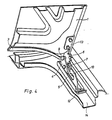
- FIG. 4 shows an embodiment of a flap hinge with which the displacement options for the flap 1 described with reference to FIGS. 1 to 3 are realized.
- the pivot bearing plate 4 on which the flap 1 is pivotably pivoted about the pivot axis 9, is guided in a guide rail 5 so as to be displaceable in the longitudinal direction of the motor vehicle.
- the pivot bearing plate 4 which is designed as an angle plate, engages in an angular guide gap 2 of the guide rail.
- a vertically standing, downwardly projecting gear segment 6 is formed such that the center of its tooth circle lies in the pivot axis 9 of the flap 1.
- the gear segment 6 engages from above in a pinion 7, which is rotatably mounted in the pivot bearing plate 4 below the pivot axis 9 and offset against it to the rear.
- the pinion 7 also engages in a lower rack 8 which is formed on the guide rail 5.
- an upper rack 10 is formed on the guide rail 5, which is arranged offset to the rear relative to the lower rack 8.
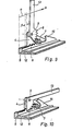
- FIGS. 9 and 10 corresponds to that of FIGS. 5 to 8 with the exception that the rear upper rack 10 is missing. Therefore, if the pinion 7 in the position according to FIG. 9 has run off the lower rack 8, the fastening arm 13 of the flap can be pivoted with the latter, the pinion 7 running freely, and in doing so, until it starts up against the rear stop 15 of the guide rail be pulled at the rear, whereby the flap is displaced by the additional dimension b.
- the position of the hinge parts in this position of the pivoted and pulled back position is shown in Fig. 10.
- the guide rail 5 is fixed outside the access opening of the usable space on the bottom of the lateral water drainage channel 14.
- the gear segment 6 and the racks 8 and 10 are laterally offset from one another, so that the height of the pivot axis 9 above the lower rack 8 is smaller than the radius of the toothed circle of the gear segment 6 can be without this colliding with the lower rack 8.
- the gear segment 6 and the swivel plate 4 are arranged perpendicular to the longitudinal direction of the vehicle at such a distance that the lower rack 8 and the upper rack 10 can protrude between the gear segment 6 and the swivel bearing plate 4.
Abstract
Description
Die Erfindung betrifft einen Personenkraftwagen, bei welchem die Front- oder insbesondere Heckklappe mit ihrem dem angrenzenden Fenster des Kraftfahrzeuges benachbarten Klappenrand an einer Schwenklagerplatte eines Scharniers auf- und abschwenkbar angelenkt ist.The invention relates to a passenger car in which the front or, in particular, tailgate is hinged with its flap edge adjacent to the adjacent window of the motor vehicle on a pivot bearing plate of a hinge and is pivotable.
Die Erfindung ist insbesondere für solche Kraftwagen vorgesehen, bei welchen der dem geneigten Fenster benachbarte Klappenrand bei geschlossener Klappe über dem unteren Falzbereich des Fensters liegt. Sie kann jedoch auch angewendet werden, wenn eine solche Oberdeckung des unteren Fensterrandes durch die Klappe nicht vorliegt. Wenngleich außerdem die Erfindung auch bei Frontklappen angewendet werden kann, wird sie bevorzugt bei Heckklappen angewendet.The invention is intended in particular for motor vehicles in which the flap edge adjacent to the inclined window lies above the lower fold area of the window when the flap is closed. However, it can also be used if there is no such covering of the lower edge of the window by the flap. In addition, although the invention can also be applied to bonnets, it is preferably applied to bonnets.
Bei derartigen Heckklappen für den Kofferraum des Kraftwagens ist ein Scharnier erforderlich, welches das Aufschwenken der Klappe ermöglicht, ohne daß diese in der aufgeschwenkten Stellung mit der angrenzenden Heckscheibe kollidiert. Hierzu können Bogenscharniere aus einem etwa U-förmigen Bügel vorgesehen sein, an dessen hinterem Ende die Klappe mit ihrem vorderen Rand festgelegt ist und dessen vorderes Ende unterhalb der Heckscheibe an einer fahrzeugfesten Schwenklagerplatte angelenkt ist. Hierbei muß die Bügellänge umso größer sein, je weiter der vordere Klappenrand über die Befestigungsstelle der Klappe an dem Bügel nach vorne hinausragt und daher die Klappe beim Aufschwenken angehoben werden muß, um eine Kollision mit der Heckscheibe zu vermeiden. Wenn daher z.B. der vordere Klappenrand soweit vorgezogen sein soll, daß er über den Fensterrahmen-Unterteil hinaus bis über den unteren Heckscheibenrand ragt, muß der Bügel verhältnismäßig lang sein. Dadurch wird die Befestigungsstabilität der Heckklappe geringer und der Platzbedarf für den Bügel im Kofferraum des Kraftwagens bei geschlossener Klappe vergrößert.In such hatchbacks for the trunk of the motor vehicle, a hinge is required which enables the hatch to be pivoted open without it colliding with the adjacent rear window in the swung-open position. For this purpose, arch hinges can be provided from an approximately U-shaped bracket, at the rear end of which the flap is fixed with its front edge and the front end of which is articulated below the rear window on a swivel bearing plate fixed to the vehicle. Here, the length of the bracket must be greater the further the front edge of the flap protrudes beyond the fastening point of the flap on the bracket and therefore the flap has to be raised when swiveling open in order to avoid a collision with the rear window. If, for example, the front flap edge is to be pulled forward far enough to protrude beyond the lower part of the window frame and beyond the lower rear window edge, the bracket must be relatively long. This will fix the stability of the tailgate is reduced and the space required for the bracket in the trunk of the motor vehicle is increased when the hatch is closed.
Wenn außerdem der vordere Klappenrand der Heckklappe verhältnismässig weit zur Heckscheibe hin vorgezogen ist, kann die Zugänglichkeit des Bereichs des unteren Fensterfalzes sowohl bei geschlossener als auch bei geöffneter Klappe beeinträchtigt sein. In diesem Fall muß die Klappe nach ihrer Vormontage und Rohbaueinstellung oder für das Ersetzen der Heckscheibe wieder ausgebaut werden, damit die Heckscheibe montiert werden kann.In addition, if the front flap edge of the tailgate is pulled out relatively far towards the rear window, the accessibility of the area of the lower window rebate can be impaired both when the flap is closed and when it is open. In this case, the flap must be removed again after it has been preassembled and adjusted to the shell or to replace the rear window so that the rear window can be installed.
Durch die Erfindung wird die Aufgabe gelöst, einen Personenkraftwagen der eingangs erwähnten Art zu schaffen, bei welchem auch bei weit zum angrenzenden Fenster des Kraftwagens hin vorgezogenem Klappenrand bei kleiner Baugröße des Scharniers weder eine Kollisionsgefahr für die Fensterscheibe bei aufgeschwenkter Klappe besteht, noch die Montage der Fensterscheibe von der montierten Klappe behindert ist.By the invention the object is achieved to create a passenger car of the type mentioned, in which there is no risk of collision for the window pane when the flap is open, even when the flap edge is pulled far toward the adjacent window of the motor vehicle, nor is the assembly of the Window pane is hindered by the mounted flap.
Dies wird gemäß der Erfindung dadurch erreicht, daß die Schwenklagerplatte in einer Führungsschiene in Fahrzeuglängsrichtung verschiebbar ist, daß zwischen den an der Schwenklagerplatte angelenkten Klappenrand und die Führungsschiene ein an der Schwenklagerplatte angreifendes Getriebe eingeschaltet ist, von welchem die Schwenklagerplatte um ein vorbestimmtes Maß beim Aufschwenken der Klappe in der dem Fenster abgewendeten Richtung, und beim Abschwenken der Klappe in der dem Fenster zugewendeten Richtung zwangsläufig verschiebbar ist, und daß wahlweise das Getriebe bei aufgeschwenkter Klappe derart entkuppelbar ist, daß die Schwenklagerplatte um ein zusätzliches Maß in der dem Fenster abgewendeten Richtung verschiebbar ist und hierbei die Klappe abschwenkbar ist.This is achieved according to the invention in that the pivot bearing plate is displaceable in a guide rail in the vehicle longitudinal direction, that between the flap edge articulated on the pivot bearing plate and the guide rail, a gear engaging on the pivot bearing plate is switched on, of which the pivot bearing plate is pivoted by a predetermined amount Flap in the direction facing away from the window, and when the flap is swiveled in the direction facing the window, it is inevitable that the gear can be uncoupled when the flap is open in such a way that the pivot bearing plate can be moved by an additional amount in the direction facing away from the window and the flap can be swung out.
Durch die Ausbildung des Scharniers gemäß der Erfindung wird beim Aufschwenken der Klappe gleichzeitig der dem Fenster benachbarte Klappenrand von diesem weg verlagert, so daß selbst bei kleiner Baugröße der Scharnierteile auch bei in der Schließlage der Klappe weit zum Fenster vorgezogenem Klappenrand eine Kollision des Klappenrandes mit der Fensterscheibe beim Aufschwenken der Klappe verhindert werden kann. Beim erneuten Abschwenken der Klappe hingegen wird diese mit ihrem Klappenrand zwangsläufig wieder in die Ausgangslage zurückverlagert, so daß der einmal eingestellte Klappenspalt genau wiederhergestellt wird.Due to the design of the hinge according to the invention, the flap edge adjacent to the window is simultaneously displaced away from the flap when the flap is swung open, so that even with a small size of the hinge parts, even when the flap edge is advanced far to the window, a flap collision occurs can be prevented with the window pane when the flap is swung open. On the other hand, when the flap is pivoted again, the flap edge of the flap is inevitably moved back to the starting position, so that the flap gap that has been set is restored exactly.
Da außerdem das die zwangsläufige Verlagerungsbewegung der Klappe bei deren Normalbetrieb steuernde Getriebe im Bedarfsfall entkuppelt werden kann und dadurch die Klappe um ein zusätzliches Maß von dem Fenster weg verlagert und abgeschwenkt werden kann, wird auch für eine Klappe, deren Klappenrand in der normalen Schließstellung verhältnismäßig weit zum Fenster hin vorgezogen ist, eine Montage der Fensterscheibe von der Klappe nicht behindert. Gleichzeitig ist ein Ausbauen der Klappe für die Montage des Fensters nicht erforderlich. Die Klappe kann vielmehr in abgeschwenkter Stellung auf dem dem Fenster abgewendeten Rahmenteil der von der Klappe absperrbaren öffnung abgelegt werden, ohne daß ihre Schwenkbefestigung an der Schwenklagerplatte gelöst wird. Für das Zurückführen der Klappe in ihre normale Betriebslage wird die Klappe wieder aufgeschwenkt und das Getriebe wieder eingekuppelt, wonach die Klappe wieder abgeschwenkt wird und dabei zwangsläufig wieder in ihre normale Schließstellung gelangt.Since, in addition, the gear which controls the inevitable displacement movement of the flap during normal operation can be uncoupled if necessary and the flap can thereby be displaced and pivoted away from the window by an additional amount, the flap whose flap edge in the normal closed position is relatively wide is pulled towards the window, assembly of the window pane is not hindered by the flap. At the same time, it is not necessary to remove the flap for installing the window. Rather, the flap can be placed in the pivoted-down position on the frame part of the opening which can be blocked off by the flap and which is turned away from the window, without its swivel fastening on the swivel bearing plate being released. To return the flap to its normal operating position, the flap is swung open again and the transmission is engaged again, after which the flap is swiveled down again and inevitably returns to its normal closed position.
Zum Ein- und Auskuppeln des Getriebes kann ein besonderes Kupplungs-oder Sperrglied vorgesehen sein, welches in einer vorbestimmten Aufschwenkstellung der Klappe vorzugsweise ohne Werkzeug betätigbar ist. Es ist auch möglich, durch die Gestaltung des Getriebes dafür zu sorgen, daß bei ganz aufgeschwenkter Klappe die zu entkuppelnden Getriebeglieder z.B. durch geringfügiges manuelles Verschieben der Schwenklagerplatte in der dem Fenster abgewendeten Richtung außer Eingriff gelangen. Hierbei kann es vorteilhaft sein, mittels eines elastischen Anschlages, einer Kugelraste oder dgl. dafür zu sorgen, daß die Klappe in diese ganz aufgeschwenkte Stellung, in welcher die Getriebeglieder auseinandergerückt werden können, erst nach überwindung eines kleinen Widerstandes aufgeschwenkt werden kann. Hierdurch wird ein unbeabsichtigtes Entkuppeln des Getriebes beim Normalbetrieb der Klappe verhindert.A special coupling or locking element can be provided for engaging and disengaging the transmission, which can preferably be operated without tools in a predetermined pivoting-open position of the flap. It is also possible to ensure through the design of the transmission that when the flap is fully opened, the transmission members to be decoupled e.g. disengage by slightly manually moving the swivel bearing plate in the direction facing away from the window. It can be advantageous here to ensure, by means of an elastic stop, a ball catch or the like, that the flap can only be swung open into this completely swung open position, in which the gear members can be moved apart, after overcoming a small resistance. This prevents unintentional decoupling of the transmission during normal operation of the flap.
Wenngleich als Getriebe ein geeignetes Koppel-Lenkergetriebe verwendet werden kann, wird das Getriebe vorzugsweise als Zahnstangentrieb ausgebildet. Ein solches Getriebe läßt sich in kompakter kleiner Baugröße unter den Seitenrändern der Klappe außerhalb des von der Klappe abgedeckten Nutzraumes in der ohnehin vorhandenen Wasserablaufrinne unterbringen. Hierdurch werden z.B. im Falle einer Heckklappe im Vergleich zu den herkömmlichen Bogenscharnieren, die beim Schließen der Klappe in den Nutzraum eintauchen, nicht nur eine bessere Ausnutzung des Nutzraumes und die Vermeidung einer Beschädigungsgefahr für Gegenstände erreicht, die in den Bewegungsfreiraum der Bogenscharniere geraten. Vielmehr kann durch eine derartige Gestaltung des Getriebes und dessen Unterbringung außerhalb des Nutzraumes eine Beeinträchtigung sonstiger Einbauten durch das Vorhandensein des Scharniers vermieden werden. Beispielsweise kann durch die Außenlage des`Scharniers jegliche Behinderung beim Tankeinbau vermieden werden, wenn der Tank in der Sicherheitszone des Nutzraumes über der Hinterachse eingebaut werden soll, jedoch die Klappe bereits eingebaut ist. Auch braucht beispielsweise das Tankfüllrohr nicht mehr um das Scharnier herumgeleitet zu werden, wie dies meist beim Vorhandensein von Bogenscharnieren erforderlich ist, oder werden beispielsweise die Austrittsquerschnitte von Luftführungsschächten durch das Vorhandensein der Schwenklagerplatte des Scharniers nicht behindert.Although a suitable coupling link transmission ver can be used, the transmission is preferably designed as a rack and pinion drive. Such a gearbox can be accommodated in a compact, small size underneath the side edges of the flap outside the usable space covered by the flap in the water drainage channel which is present anyway. In this way, for example, in the case of a tailgate, compared to the conventional arch hinges that plunge into the usable space when the flap is closed, not only is better utilization of the usable space achieved and the risk of damage to objects avoided, which get into the freedom of movement of the arch hinges. Rather, such a design of the gearbox and its placement outside the usable space can prevent other installations from being impaired by the presence of the hinge. For example, the outer position of the hinge can prevent any obstruction when installing the tank if the tank is to be installed in the safety zone of the usable space above the rear axle, but the flap is already installed. Also, for example, the tank filler tube no longer needs to be directed around the hinge, as is usually required when arched hinges are present, or, for example, the outlet cross-sections of air ducts are not hindered by the presence of the pivot bearing plate of the hinge.
In der bevorzugten Ausführungsform eines derartigen Zahnstangengetriebes, welches sich für die Anordnung außerhalb des Nutzraumes seitlich von dessen Uffnung in der Wasserablaufrinne eignet, weist das Getriebe ein mit der Klappe um deren Schwenkachse drehbares Zahnradsegment, eine an der Führungsschiene ausgebildete untere Zahnstange und ein zwischen dieser und dem Zahnradsegment angeordnetes, mit dem Zahnradsegment in Eingriff stehendes, an der Schwenklagerplatte gelagertes Ritzel auf, welches bei der zwangsläufigen Verschiebung der Schwenklagerplatte in die untere Zahnstange eingreift und von dieser bei aufgeschwenkter Klappe entkuppelbar ist.In the preferred embodiment of such a rack and pinion gear, which is suitable for the arrangement outside the usable space laterally from its opening in the water drainage channel, the gear has a gear segment rotatable with the flap about its pivot axis, a lower rack formed on the guide rail and a between this and arranged on the gear segment, engaging with the gear segment and mounted on the pivot bearing plate, which engages in the inevitable displacement of the pivot bearing plate in the lower rack and can be uncoupled from the latter when the flap is pivoted open.
Daher wird beim Aufschwenken der Klappe das Ritzel von dem Zahnradsegment gedreht, so daß es sich auf der Zahnstange abwälzt und durch seine Lagerung an der Schwenklagerplatte diese entsprechend verschiebt. Die Zahnstange kann an einer Stelle enden, an welcher das Ritzel von ihr ggf. nach überwindung eines elastischen Widerstandes abläuft und dadurch von der Zahnstange entkuppelt wird. Dann ist auch die Schwenklagerplatte nicht mehr an der Zahnstange abgestützt und kann um das gewünschte zusätzliche Maß verlagert werden, wobei das Ritzel freiläuft. Hierdurch kann die Klappe abgeschwenkt werden.Therefore, when the flap is swung open, the pinion is rotated by the gear segment, so that it rolls on the rack and is displaced accordingly by its mounting on the pivot bearing plate. The toothed rack can end at a point at which the pinion may move away from it after overcoming elastic resistance runs and is uncoupled from the rack. Then the pivot bearing plate is no longer supported on the rack and can be shifted by the desired additional dimension, the pinion freewheeling. As a result, the flap can be pivoted away.
Wenn aber das Ritzel nach seinem Ablaufen von der Zahnstange beim Abschwenken der Klappe freiläuft, ist es möglich, daß der Eingriff zwischen dem Ritzel und der Zahnstange beim späteren erneuten Aufschwenken der Klappe und dem Zurückschieben der Schwenklagerplatte mit dem Ritzel in einer anderen Schwenkstellung der Klappe als beim früheren Ablaufen des Ritzels von der Zahnstange hergestellt wird. Daher wird es in einer Ausgestaltung dieser Ausführungsform gemäß der Erfindung vorgeschlagen, auch die Verlagerung der Schwenklagerplatte um das zusätzliche Maß zwangsläufig durch das Abschwenken der Klappe herbeizuführen und daher auch das Rückverlagern der Schwenklagerplatte durch späteres erneutes Aufschwenken der Klappe ebenfalls zwangsläufig zu gestalten. Vorzugsweise ist hierzu an der Führungsschiene eine zweite, obere Zahnstange ausgebildet, welche gegenüber der unteren Zahnstange zu der dem Fenster abgewendeten Richtung hin versetzt ist und welche für das Verschieben der Schwenklagerplatte um das zusätzliche Maß von oben mit dem Ritzel in Eingriff gelangt. Mit dem Ablaufen des Ritzels von der unteren Zahnstange beim ersten Hochschwenken der Klappe läuft dann beim sich anschließenden Abschwenken der Klappe das Ritzel in die obere Zahnstange ein und rollt an dieser oberen Zahnstange ab, wodurch die Schwenklagerplatte mitgezogen wird, bis die Klappe vollständig abgeschwenkt ist. Diese Vorgänge laufen beim erneuten Aufschwenken und Abschwenken der Klappe umgekehrt ab, so daß die Klappe zwangsläufig wieder in ihre normale Betriebslage gebracht wird.If, however, the pinion frees after it has run off the rack when the flap is pivoted down, it is possible that the engagement between the pinion and the rack when the flap is pivoted open again later and the pivoting bearing plate with the pinion is pushed back in a different pivoting position of the flap than is produced when the pinion runs off the rack earlier. Therefore, in an embodiment of this embodiment according to the invention, it is also necessary to bring about the additional amount of displacement of the pivot bearing plate by pivoting the flap away and therefore also to make the pivoting of the pivot bearing plate back by pivoting the flap again later. For this purpose, a second, upper toothed rack is preferably formed on the guide rail, which is offset relative to the lower toothed rack in the direction facing away from the window and which engages with the pinion for moving the swivel bearing plate by the additional dimension from above. When the pinion runs off the lower rack when the flap is first swung up, the pinion then runs into the upper rack when the flap is swiveled down and rolls on this upper rack, pulling the swivel bearing plate until the flap is completely pivoted. These processes are reversed when the flap is swung open and swung again, so that the flap is inevitably brought back into its normal operating position.
Die Erfindung wird anhand von Ausführungsformen erläutert, die wenigstens schematisch aus der Zeichnung ersichtlich sind. In der Zeichnung zeigt:
- Fig. 1 schematisch einen Personenkraftwagen im Bereich des Heckfensters und der Heckklappe bei geschlossener Klappe,
- Fig. 2 die Schemazeichnung aus Fig. 1, jedoch bei geöffneter Klappe,
- Fig. 3 die Schemazeichnung aus Fig. 1 bei abgeschwenkter, jedoch für die Scheibenmontage am Heckfenster zurückverlagerter Klappe,
- Fig. 4 eine perspektivische Darstellung einer bevorzugten Ausführungsform eines erfindungsgemäßen Scharniers einer Heckklappe,
- Fig. 5 bis 8 das Scharnier aus Fig. 4 bei geschlossener Klappe, beim öffnen der Klappe, bei voll geöffneter Klappe und bei wieder abgeschwenkter Klappe und
- Fig. 9 und 10 abgewandelte Ausführungsformen des Scharniers bei aufgeschwenkter bzw. abgeschwenkter Klappe.
- 1 schematically shows a passenger car in the area of the rear window and the tailgate with the hatch closed,
- F ig. 2 shows the schematic drawing from FIG. 1, but with the flap open,
- 3 shows the schematic drawing from FIG. 1 with the flap pivoted away, but moved back for the window assembly on the rear window,
- 4 shows a perspective illustration of a preferred embodiment of a hinge of a tailgate according to the invention,
- Fig. 5 to 8, the hinge from Fig. 4 with the flap closed, when opening the flap, with the flap fully open and when the flap is swung back and
- 9 and 10 modified embodiments of the hinge with the flap swung open or swung open.
Die aerodynamische Formoptimierung eines Personenkraftwagens kann entsprechend Fig. 1 zur Folge haben, daß die Heckklappe 1 wegen der flach geneigten Einbaulage des Heckfensters 2 mit ihrem diesem benachbarten Klappenrand 3 den unteren Rahmenteil des Fensters 2 überlappt. Gemäß Fig. 1 ist die Klappe 1 über weit um das Heckfenster 2 herumgezogene Befestigungsarme 11 am Kraftwagen angelenkt, so daß ihre Schwenkachse 9 unterhalb des Fensters liegt. Beim Aufschwenken der Klappe 1 wird gleichzeitig entsprechend Fig. 2 die Schwenkachse 9 um ein vorbestimmtes Maß a nach hinten verlagert, damit der vordere Klappenrand 3 der aufgeschwenkten Hechklappe 1 nicht an der Scheibe des Fensters 2 anstößt und daher weder die Scheibe noch der Klappenrand 3 beschädigt werden können.The aerodynamic shape optimization of a passenger car can result in accordance with FIG. 1 that the
Bei der Rohmontage des Kraftwagens wird die Klappe 1 zeitlich vor der Scheibe des Fensters 2 eingebaut. Wegen der Oberlappung d des unteren Fensterrahmenteils durch den vorderen Klappenrand 3 kann jedoch die Scheibe des Fensters 2 weder bei geschlossener Klappe 1 entsprechend Fig. 1 noch bei geöffneter Klappe 1 entsprechend Fig. 2 eingebaut werden. Gleichwohl ist jedoch bei dem gezeigten Kraftwagen das Einbauen der Scheibe des Fensters 2 ohne ein Wiederausbauen der Klappe 1 für die Scheibenmontage und ihr erneutes Einbauen nach der Scheibenmontage möglich, weil die Klappe 1 entsprechend Fig. 3 bedarfsweise aus der aufgeschwenkten Lage um ein zusätzliches Maß b nach hinten verlagert und abgeschwenkt werden kann. Dadurch ist die Vorderkante des vorderen Klappenrandes 3 um einen hinreichend großen Abstand c gegen den unteren Rahmenteil des Fensters nach hinten versetzt angeordnet, wodurch die Scheibe 2 ohne Beschädigungsgefahr für sie selbst oder den Klappenrand 3 problemlos eingebaut werden kann. Entsprechend kann dadurch die Scheibe des Fensters 2 gegen eine neue Scheibe ersetzt werden, ohne hierzu die Klappe 1 ausbauen zu müssen.During the rough assembly of the motor vehicle, the
Fig. 4 zeigt eine Ausführungsform eines Klappenscharniers, mit welcher die anhand der Fig. 1 bis 3 geschilderten Verlagerungsmöglichkeiten für die Klappe 1 verwirklicht werden. Wie auch aus den Fig: 5 bis 8 ersichtlich, ist die Schwenklagerplatte 4, an welcher die Klappe 1 um die Schwenkachse 9 schwenkbar angelenkt ist, in einer Führungsschiene 5 in Längsrichtung des Kraftwagens verschiebbar geführt. Hierzu greift die als Winkelplatte ausgebildete Schwenklagerplatte 4 in einen winkelförmigen Führungsspalt 2 der Führungsschiene ein.FIG. 4 shows an embodiment of a flap hinge with which the displacement options for the
An dem Befestigungsarm 13, mit welchem die Klappe 1 fest verschraubt ist, ist ein vertikal stehendes, nach unten ragendes Zahnradsegment 6 derart ausgebildet, daß der Mittelpunkt seines Zahnkreises in der Schwenkachse 9 der Klappe 1 liegt. Das Zahnradsegment 6 greift von oben in ein Ritzel 7 ein, welches in der Schwenklagerplatte 4 unterhalb der Schwenkachse 9 und gegen diese nach hinten versetzt drehbar gelagert ist. Im Normalbetrieb der Klappe 1 greift außerdem das Ritzel 7 seinerseits in eine untere Zahnstange 8 ein, die an der Führungsschiene 5 ausgebildet ist. Ferner ist an der Führungsschiene 5 eine obere Zahnstange 10 ausgebildet, welche gegenüber der unteren Zahnstange 8 nach hinten versetzt angeordnet ist.On the mounting
Beim Auf- und Abschwenken der Klappe 1 wird daher das Ritzel 7 von dem Zahnradsegment 6 zwangsläufig gedreht, so daß es auf der unteren Zahnstange 8 oder der oberen Zahnstange 10 abgerollt wird und dabei die Schwenklagerplatte 4 mitnimmt, so daß diese in dem Führungsspalt 12 der Führungsschiene 5 in Fahrzeuglängsrichtung verschoben wird. Die einzelnen Bewegungsphasen werden anhand der Fig. 5 bis 8 erläutert, wo von der Klappe nur ihr Befestigungsarm 13 gezeigt ist.When pivoting the
In der normalen Schließlage der Klappe, die in Fig. 5 gezeigt ist, greift das mit dem Zahnradsegment 6 im Eingriff befindliche Ritzel 7 von oben her in die untere Zahnstange 8 ein und befindet sich in einer Stellung, in welcher die Schwenklagerplatte 4 und daher die -Schwenkachse 9 der Klappe ihre vorderste Stellung einnehmen. Wenn nun entsprechend Fig. 6 der Befestigungsarm 13 mit der Klappe nach oben geschwenkt wird und daher das Zahnradsegment 6 entgegen dem Uhrzeigersinn gedreht wird, wird das Ritzel im Uhrzeigersinn gedreht, so daß es auf der unteren Zahnstange 8 nach hinten abrollt und die Schwenklagerplatte 4 mit der Schwenkachse 9 nach hinten verlagert wird. Wenn die Klappe mit dem Befestigungsarm 13 sich in der ganz aufgeschwenkten Stellung entsprechend Fig. 7 befindet, sind die Schwenklagerplatte 4 und die Schwenkachse 9 der Klappe um das vorbestimmte Maß a nach hinten verschoben, wohingegen das Ritzel 7 mit der Zahnstange 8 eben noch in Eingriff steht. Wenn jetzt der Befestigungsarm 13 wieder abgeschwenkt wird, wird das Ritzel 7 von dem Zahnradsegment 6 entgegen dem Uhrzeigersinn gedreht und auf der unteren Zahnstange 8 wieder nach vorn gerollt, so daß die Schwenklagerplatte 4 mit der Schwenkachse 9 der Klappe und somit diese wieder nach vorne verlagert werden, bis sie wieder bei vollständig geschlossener Klappe ihre vorderste Stellung entsprechend Fig. 5 einnehmen.In the normal closed position of the flap, which is shown in Fig. 5, the
Wenn jedoch der Befestigungsarm 13 der Klappe aus der Stellung gemäß Fig. 7 noch etwas weiter aufgeschwenkt wird, läuft das Ritzel 7 von der unteren Zahnstange 5 ab und wird daher von dieser entkuppelt. Dadurch wird auch die zwangsläufige Getriebeverbindung zwischen der Schwenklagerplatte 4 und der feststehenden Führungsschiene 5 entkuppelt, so daß die Schwenklagerplatte 4 um ein kleines Maß e nach hinten gerückt werden kann und dadurch das Ritzel 7 von unten her in den Eingriff mit der oberen Zahnstange 10 der Führungsschiene 5 gelangt. Wenn nun der Befestigungsarm 13 der Klappe wieder abgeschwenkt wird, wird das von dem Zahnradsegment 6 wieder entgegen dei Uhrzeigersinn gedrehte Ritzel 7 unter der oberen Zahnstange 10 nact hinten gerollt, wodurch die Schwenklagerplatte 4 und daher auch di: daran angelenkte Klappe um das zusätzliche Maß b nach hinten verl - gert werden. Beim erneuten Aufschwenken des Befestigungsarms 13 er Klappe wird wieder die Stellung nach Fig. 7 erreicht, so daß dif Schwenklagerplatte 4 mit dem Ritzel 7 wieder um das kleine Maß e nach vorne gerückt werden kann und dadurch das Ritzel 7 für den Normalbetrieb der Klappe wieder mit der unteren Zahnstange 8 in Eingriff gelangt. Durch erneutes Abschwenken der Klappe gelangt diese dann wieder in ihre normale Schließlage entsprechend Fig. 5.However, if the
Die Ausführungsform aus den Fig. 9 und 10 entspricht derjenigen aus den Fig. 5 bis 8 mit der Ausnahme, daß die hintere obere Zahnstange 10 fehlt. Wenn daher das Ritzel 7 in der Stellung nach Fig. 9 von der unteren Zahnstange 8 abgelaufen ist, kann der Befestigungsarm 13 der Klappe mit dieser abgeschwenkt werden, wobei das Ritzel 7 freiläuft, und dabei bis zum Anlaufen an dem hinteren Anschlag 15 der Führungsschiene nach hinten gezogen werden, wodurch die Verlagerung der Klappe um das zusätzliche Maß b erreicht wird. Die Stellung der Scharnierteile bei dieser Lage der abgeschwenkten und nach hinten gezogenen Stellung ist aus Fig. 10 ersichtlich.The embodiment of FIGS. 9 and 10 corresponds to that of FIGS. 5 to 8 with the exception that the rear
Wie in Fig. 4 gezeigt, ist die Führungsschiene 5 außerhalb der Zutrittsöffnung des Nutzraumes am Boden der seitlichen Wasserablaufrinne 14 festgelegt. Um hierzu eine möglichst kleine Bauhöhe zu erreichen, sind entsprechend den Fig. 5 bis 8 das Zahnradsegment 6 und die Zahnstangen 8 und 10 seitlich gegeneinander versetzt, so daß die Höhe der Schwenkachse 9 über der unteren Zahnstange 8 kleiner als der Radius des Zahnkreises des Zahnradsegmentes 6 sein kann, ohne daß dieses mit der unteren Zahnstange 8 kollidiert. Das Zahnradsegment 6 und die Schwenkplatte 4 sind senkrecht zur Fahrzeuglängsrichtung in einem solchen Abstand angeordnet, daß die untere Zahnstange 8 und die obere Zahnstange 10 zwischen das Zahnradsegment 6 und die Schwenklagerplatte 4 hineinragen können.As shown in FIG. 4, the
Claims (3)
Applications Claiming Priority (2)
| Application Number | Priority Date | Filing Date | Title |
|---|---|---|---|
| DE3445812 | 1984-12-15 | ||
| DE19843445812 DE3445812A1 (en) | 1984-12-15 | 1984-12-15 | PASSENGER VEHICLE |
Publications (3)
| Publication Number | Publication Date |
|---|---|
| EP0185246A2 true EP0185246A2 (en) | 1986-06-25 |
| EP0185246A3 EP0185246A3 (en) | 1987-01-07 |
| EP0185246B1 EP0185246B1 (en) | 1989-03-22 |
Family
ID=6252875
Family Applications (1)
| Application Number | Title | Priority Date | Filing Date |
|---|---|---|---|
| EP85115362A Expired EP0185246B1 (en) | 1984-12-15 | 1985-12-04 | Rear or front lid hinge of a passenger car |
Country Status (2)
| Country | Link |
|---|---|
| EP (1) | EP0185246B1 (en) |
| DE (2) | DE3445812A1 (en) |
Cited By (1)
| Publication number | Priority date | Publication date | Assignee | Title |
|---|---|---|---|---|
| DE102010007898A1 (en) | 2010-02-13 | 2011-08-18 | Volkswagen AG, 38440 | Front end of a vehicle |
Families Citing this family (4)
| Publication number | Priority date | Publication date | Assignee | Title |
|---|---|---|---|---|
| DE3743502A1 (en) * | 1987-12-22 | 1989-07-06 | Bayerische Motoren Werke Ag | Mounting of a foldable cover of a motor vehicle, in particular of a folding-top compartment cover |
| DE3815450C2 (en) * | 1988-05-06 | 1995-03-09 | Grass Alfred Metallwaren | Wide-angle hinge with gear transmission |
| DE19944436A1 (en) * | 1999-09-16 | 2001-03-22 | Volkswagen Ag | Front part of vehicle, with turning bearing able to move in rear region of front part on bodywork base structure |
| US7283897B2 (en) * | 2002-05-31 | 2007-10-16 | Quantum Engineering, Inc. | Method and system for compensating for wheel wear on a train |
Citations (4)
| Publication number | Priority date | Publication date | Assignee | Title |
|---|---|---|---|---|
| DE1216134B (en) * | 1961-10-10 | 1966-05-05 | Auto Union Gmbh | Joint for flaps, covers or the like, especially on motor vehicles |
| DE2651410A1 (en) * | 1976-11-11 | 1978-05-18 | Daimler Benz Ag | Hinge for vehicle hood or door - has cranked guide lever and rotating gear wheel engaging with toothed segment held on fixed body part |
| DE3315129A1 (en) * | 1983-04-27 | 1984-10-31 | Bayerische Motoren Werke AG, 8000 München | Hinge for flaps on motor vehicles |
| EP0141145A2 (en) * | 1983-09-08 | 1985-05-15 | Bayerische Motoren Werke Aktiengesellschaft, Patentabteilung AJ-3 | Articulated connection for a body post to a vehicle, especially for a boot lid of a passenger car |
Family Cites Families (1)
| Publication number | Priority date | Publication date | Assignee | Title |
|---|---|---|---|---|
| DE2846307A1 (en) * | 1977-10-25 | 1979-04-26 | Alfa Romeo Spa | JOINT CONNECTION FOR THE FRONT AND / OR REAR TRUNK COMPARTMENT OF A MOTOR VEHICLE |
-
1984
- 1984-12-15 DE DE19843445812 patent/DE3445812A1/en not_active Withdrawn
-
1985
- 1985-12-04 DE DE8585115362T patent/DE3569008D1/en not_active Expired
- 1985-12-04 EP EP85115362A patent/EP0185246B1/en not_active Expired
Patent Citations (4)
| Publication number | Priority date | Publication date | Assignee | Title |
|---|---|---|---|---|
| DE1216134B (en) * | 1961-10-10 | 1966-05-05 | Auto Union Gmbh | Joint for flaps, covers or the like, especially on motor vehicles |
| DE2651410A1 (en) * | 1976-11-11 | 1978-05-18 | Daimler Benz Ag | Hinge for vehicle hood or door - has cranked guide lever and rotating gear wheel engaging with toothed segment held on fixed body part |
| DE3315129A1 (en) * | 1983-04-27 | 1984-10-31 | Bayerische Motoren Werke AG, 8000 München | Hinge for flaps on motor vehicles |
| EP0141145A2 (en) * | 1983-09-08 | 1985-05-15 | Bayerische Motoren Werke Aktiengesellschaft, Patentabteilung AJ-3 | Articulated connection for a body post to a vehicle, especially for a boot lid of a passenger car |
Cited By (2)
| Publication number | Priority date | Publication date | Assignee | Title |
|---|---|---|---|---|
| DE102010007898A1 (en) | 2010-02-13 | 2011-08-18 | Volkswagen AG, 38440 | Front end of a vehicle |
| WO2011098110A1 (en) | 2010-02-13 | 2011-08-18 | Volkswagen Aktiengesellschaft | Front end of a vehicle |
Also Published As
| Publication number | Publication date |
|---|---|
| DE3569008D1 (en) | 1989-04-27 |
| EP0185246A3 (en) | 1987-01-07 |
| EP0185246B1 (en) | 1989-03-22 |
| DE3445812A1 (en) | 1986-06-19 |
Similar Documents
| Publication | Publication Date | Title |
|---|---|---|
| EP0261379B1 (en) | Collapsible hood for vehicles | |
| DE3209052C2 (en) | ||
| DE4014380A1 (en) | MOTOR VEHICLE, ESPECIALLY A PASSENGER CAR, WITH AN AIR GUIDE ARRANGED IN THE REAR AREA | |
| EP0085173A1 (en) | Ventilation device | |
| WO2004065740A1 (en) | Hinge | |
| DE2936051C2 (en) | Lifting device for a motor vehicle sunroof | |
| DE2507893A1 (en) | WINDOW REGULATORS FOR VERTICAL SLIDING MOTOR VEHICLE WINDOWS | |
| EP1403132A2 (en) | Drive for realising a rotation-tilting for a component, in particular in the passenger compartment of vehicles | |
| DE2405881C2 (en) | Window lifter for a vertically divided door window of motor vehicles | |
| EP0185993B1 (en) | Vehicle sliding roof | |
| EP1758752B1 (en) | Convertible | |
| DE3823087A1 (en) | GUIDE DEVICE FOR THE WINDOW WINDOWS WITHIN THE ASSEMBLY OF AN AUTOMOTIVE DOOR | |
| EP0185246A2 (en) | Rear or front lid hinge of a passenger car | |
| WO2020114749A1 (en) | Cover device for a side sill of a passenger car | |
| DE102005059274B4 (en) | Facing device for vehicle roof systems with openable lid | |
| DE4040372A1 (en) | AUTOMATIC OPENING AND CLOSING DEVICE FOR A TAILGATE | |
| EP0645270B1 (en) | Wind deflector for motor vehicle convertible top | |
| DE19922586A1 (en) | Window roller blind, particularly for use in road vehicles | |
| DE102020209607B4 (en) | Closure arrangement for closing a tank trough of a motor vehicle body | |
| DE3924035C1 (en) | ||
| EP2004432A1 (en) | Hardtop folding roof for an open motor vehicle | |
| EP0551840B1 (en) | Sliding sunroof for motorvehicle | |
| DE19737059C2 (en) | Linkage for a convertible top compartment lid | |
| DE102004007606B4 (en) | Exterior mirrors for a motor vehicle | |
| EP1581712B1 (en) | Mounting unit for a window or a door |
Legal Events
| Date | Code | Title | Description |
|---|---|---|---|
| PUAI | Public reference made under article 153(3) epc to a published international application that has entered the european phase |
Free format text: ORIGINAL CODE: 0009012 |
|
| AK | Designated contracting states |
Kind code of ref document: A2 Designated state(s): DE FR GB IT |
|
| PUAL | Search report despatched |
Free format text: ORIGINAL CODE: 0009013 |
|
| AK | Designated contracting states |
Kind code of ref document: A3 Designated state(s): DE FR GB IT |
|
| 17P | Request for examination filed |
Effective date: 19870120 |
|
| 17Q | First examination report despatched |
Effective date: 19880112 |
|
| GRAA | (expected) grant |
Free format text: ORIGINAL CODE: 0009210 |
|
| AK | Designated contracting states |
Kind code of ref document: B1 Designated state(s): DE FR GB IT |
|
| REF | Corresponds to: |
Ref document number: 3569008 Country of ref document: DE Date of ref document: 19890427 |
|
| ET | Fr: translation filed | ||
| ITF | It: translation for a ep patent filed |
Owner name: STUDIO JAUMANN |
|
| GBT | Gb: translation of ep patent filed (gb section 77(6)(a)/1977) | ||
| PLBE | No opposition filed within time limit |
Free format text: ORIGINAL CODE: 0009261 |
|
| STAA | Information on the status of an ep patent application or granted ep patent |
Free format text: STATUS: NO OPPOSITION FILED WITHIN TIME LIMIT |
|
| 26N | No opposition filed | ||
| ITTA | It: last paid annual fee | ||
| PGFP | Annual fee paid to national office [announced via postgrant information from national office to epo] |
Ref country code: GB Payment date: 19911204 Year of fee payment: 7 |
|
| PGFP | Annual fee paid to national office [announced via postgrant information from national office to epo] |
Ref country code: FR Payment date: 19911230 Year of fee payment: 7 |
|
| PG25 | Lapsed in a contracting state [announced via postgrant information from national office to epo] |
Ref country code: GB Effective date: 19921204 |
|
| GBPC | Gb: european patent ceased through non-payment of renewal fee |
Effective date: 19921204 |
|
| PG25 | Lapsed in a contracting state [announced via postgrant information from national office to epo] |
Ref country code: FR Effective date: 19930831 |
|
| REG | Reference to a national code |
Ref country code: FR Ref legal event code: ST |
|
| PGFP | Annual fee paid to national office [announced via postgrant information from national office to epo] |
Ref country code: DE Payment date: 19931203 Year of fee payment: 9 |
|
| PG25 | Lapsed in a contracting state [announced via postgrant information from national office to epo] |
Ref country code: DE Effective date: 19950901 |