EP0184995A2 - Reinforcement system preventing shearing - Google Patents
Reinforcement system preventing shearing Download PDFInfo
- Publication number
- EP0184995A2 EP0184995A2 EP85810587A EP85810587A EP0184995A2 EP 0184995 A2 EP0184995 A2 EP 0184995A2 EP 85810587 A EP85810587 A EP 85810587A EP 85810587 A EP85810587 A EP 85810587A EP 0184995 A2 EP0184995 A2 EP 0184995A2
- Authority
- EP
- European Patent Office
- Prior art keywords
- push
- connecting rods
- reinforcement
- bars
- cross
- Prior art date
- Legal status (The legal status is an assumption and is not a legal conclusion. Google has not performed a legal analysis and makes no representation as to the accuracy of the status listed.)
- Granted
Links
Images

Classifications
-
- E—FIXED CONSTRUCTIONS
- E04—BUILDING
- E04C—STRUCTURAL ELEMENTS; BUILDING MATERIALS
- E04C5/00—Reinforcing elements, e.g. for concrete; Auxiliary elements therefor
- E04C5/01—Reinforcing elements of metal, e.g. with non-structural coatings
- E04C5/06—Reinforcing elements of metal, e.g. with non-structural coatings of high bending resistance, i.e. of essentially three-dimensional extent, e.g. lattice girders
- E04C5/0645—Shear reinforcements, e.g. shearheads for floor slabs
-
- E—FIXED CONSTRUCTIONS
- E04—BUILDING
- E04B—GENERAL BUILDING CONSTRUCTIONS; WALLS, e.g. PARTITIONS; ROOFS; FLOORS; CEILINGS; INSULATION OR OTHER PROTECTION OF BUILDINGS
- E04B5/00—Floors; Floor construction with regard to insulation; Connections specially adapted therefor
- E04B5/43—Floor structures of extraordinary design; Features relating to the elastic stability; Floor structures specially designed for resting on columns only, e.g. mushroom floors
Definitions
- the invention relates to a shear reinforcement system to ensure the load-bearing capacity of zones of reinforced concrete plates that are subject to shear forces, in particular zones of flat slabs that are at risk of punching, each with a lower and upper reinforcement included therein, running parallel to the flat slab and comprising at least one reinforcement layer.
- a common example of such a reinforced concrete slab is the flat ceiling above an extensive underground parking space for commercial vehicles, on which there is a parking lot, and which rests all around on walls, but between them on a support or the majority thereof.
- a shear load acts on the ceiling, but a much larger one on the much smaller circumference of a column.
- an upward transverse force acts on the ceiling, but immediately outside this area there is a downward force of the same amount from the weight of the ceiling and its load, i.e. along the circumference of the column, the ceiling is severely sheared and in the surrounding zone Bend claims what is known to be a very unfavorable type of stress in concrete. This creates the danger that the ceiling will be punched through there.
- zones of reinforced concrete slabs e.g. Flat ceilings
- an extremely complex and dense steel reinforcement e.g. consisting of lower and upper reinforcement layers crossing one another in the longitudinal and transverse directions, connected by countless individual so-called push bars, the placement and fastening of which is extremely critical, and when assembling you usually have to do spacing -Devices to help and you can at least partially the reinforcement bars just insert lengthways.
- Some embodiments of the new push reinforcement system have the common feature that the connecting rods directly above and / or under the webs of the push bar in a mutual distance parallel to each other, which is smaller than the push bar width, and that the push bars are perpendicular to the connecting rods and along these, at least insofar as it is not the outer on both sides, so alternately laterally offset that they are at least two each Cross connecting rods and, thanks to the arrangement and firm connection at the intersection points, bring about a firm connection of all connecting rods with one another, so that the drawer element as a whole forms a coherent whole.
- the push bars in the direction of the connecting rods are at least approximately evenly spaced in rows and they are laterally offset along one of the connecting rods in such a way that they alternate between this and the adjacent connecting rod on the left, this and the adjacent connecting rod on the right, and the two left and right adjacent connecting rods, but then do not cross the relevant connecting rod itself and are firmly connected to it.
- At least some of the connecting rods can be interrupted where push bars cross the two connecting rods on the left and right, but not the connecting rod in question.
- the other of these variants maintains the uniformity of the structure when assembling two or more push cage elements in that push bars of full width are alternately provided at least along one outer connecting bar, which push bars cross the outer and the next inner connecting bar and are firmly connected thereto, and push bars of less , eg half width, which only cross the outer connecting rod and are firmly connected to it.
- Another embodiment with the aforementioned common feature is designed so that the distance from push bar to push bar in the direction of the connecting rods is alternately equal to a constant value and zero, and that in the latter case the two adjoining push bars 33 forming a pair of push bars are laterally offset from each other that one leg of one is in the middle between the legs of the other. In this case, equal distances between the push arm legs in the longitudinal direction and in the transverse direction are made possible, which will be discussed in more detail below.
- longitudinal connecting rods and cross connecting rods are provided as connecting rods, each of which runs parallel to one another at a distance from rod to rod approximately equal to twice the push bar width, cross each other at right angles and at their crossing points are firmly connected to each other, and that push bars are arranged transversely to each longitudinal connecting rod, which they cross in the middle of their web, where they are firmly connected to it. It is then expedient to arrange the push bars on the longitudinal connecting rods approximately in the middle between the transverse connecting rods. So this is a very regular arrangement: the individual push bars are aligned with each other in the longitudinal and transverse directions. They do not have to connect connecting rods, but the cross-connecting rods serve this purpose separately,
- a variant of this is that longitudinal and transverse connecting rods are provided as connecting rods, each of which is at a distance from rod to rod equal to the push bar width, cross each other at right angles and is firmly connected to one another at their crossing points, and that the push bar is transverse stand on two adjacent longitudinal connecting rods and cross them at the lower end of their legs, where they are firmly connected to them.
- the smaller distances between the connecting rods compared to the previous one, as well as the additional connection of two rods by the push bar naturally lead to greater stability of the entire push basket element;
- the first step here is to attach the push bars as regularly as in the previous arrangement, i.e. such that they are aligned with each other in the longitudinal and transverse directions, and the thrust arm legs can also be given equal distances in both directions.
- a connection at the crossing points can be e.g. Manufacture by using a pipe fitting consisting of three mutually perpendicular pieces of pipe and inserting the longitudinal and transverse connecting rod as well as the push bracket leg in order to glue them, e.g. with an epoxy resin with hardener or with a cyanoacrylate.
- the push bars laterally offset, so that they alternately connect this along a longitudinal connecting rod with the one on the left and the one on the right.
- the cross-connecting rods can also be omitted.
- the push bars are hook-like bent by at least approximately 180 ° in such a way that bars of the upper reinforcement can be inserted into the hook-like bends, and that the push bars are aligned for the same purpose so that the hook-like bends are aligned with one another in rows.
- the legs of the push bars can each have the same distances from one another in the longitudinal direction and in the transverse direction.
- the arm leg density is then isotropic. This is advantageous if the transverse force is approximately the same in both directions or approximately constant around the support. Another advantage is that with large transverse forces you can choose correspondingly small stirrup leg distances without necessarily having to accept smaller ones in one direction, which results in a corresponding saving in material.
- the other embodiments with a fundamentally anisotropic stirrup leg density are in place when transverse forces of different magnitudes are specified in the longitudinal and transverse directions; of course such drawer elements must then be correctly arranged on the construction site - not rotated by 90 °, i.e. then they are not easily foolproof.
- the connecting rods or the longitudinal connecting rods and / or the transverse connecting rods have a smaller mutual distance in the area of the edges of the drawer element than in the middle, and / or that transverse connecting rods are only provided in the relevant edge areas in addition to the longitudinal connecting rods .
- the described embodiments suggest others to those skilled in the art, including those where the drawer element is not, as is most often used, rectangular or in plan is square, but has such a shape that it can be inscribed in a parallelogram, circle or circle sector.
- the connecting rods can run parallel to two mutually opposite parallelogram sides or be arranged radially.
- the material from which the drawer element is made is worth mentioning, because it plays a crucial role in the strength and durability of a building in places of high stress.
- the durability is not a decisive factor or, in the opinion of the owner, besides irrelevant of the costs, the drawer element can consist of ordinary reinforcing steel in the way that has long been common for reinforcement parts.
- the drawer element be made of smooth or at least partially profiled round steel, which is coated with a corrosion-resistant and diffusion-tight plastic, or of stainless steel.
- a corrosion-resistant and diffusion-tight plastic or of stainless steel.
- the suitability of the latter is beyond question and the higher costs are disproportionate to the damage it prevents.
- Certain acids, to a certain extent, are attacked by certain acids if they are very dilute and therefore have a high degree of dissociation, but this is only manifested by a surface discoloration, which is not accompanied by a noticeable increase in volume.
- Cocosamine after curing, this is sufficiently elastic even without a plasticizer, so that it does not form any cracks as a coating, and is perfectly diffusion-tight even against the smallest molecules, and it is also one of the few plastics that are permanently resistant to those pollutants. However, this does not exclude that other plastics with properties suitable for the present purpose are found.
- FIG. 1 shows on a support 1, which is indicated with a bold square, a section of a flat slab 2, while the new shear reinforcement system in it hinted at with four composite drawer elements 3 or a correspondingly larger, and with longitudinally extending lower and upper reinforcement layers 4, 4 'and transverse and lower and upper reinforcement layers 5, 5 ".
- FIG. 1 is viewed as a view from above
- FIG. 2 is the section through the support 1 of the same arrangement seen from the lower edge of the sheet
- the representation of the drawer element 3 in FIG. 2 could only correspond to a specific embodiment - the one from FIGS. 9 to 11 was chosen - but is not to be understood in particular why here also all parts of the drawer element, generally meant according to the invention, are denoted uniformly by 3.
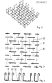
- a first embodiment of the drawer element is shown in Figures 3 to 5; in Figure 3 in top view, in Figure 4 in side view from the direction in Figure 3 below, in Figure 5 for illustration in perspective.
- the mutual distance from connecting rods 32 is smaller than the width of push bars 30, each of which is firmly connected to the two connecting bars 32 crossing it, while narrower push bars 31 at the edge ensure a more uniform finish.
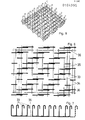
- the mutual spacing of connecting rods 35 is smaller than the width of push bars 33 crossing them, each of which crosses two connecting rods and is firmly connected thereto; the mutual distance of the push bars 33 in the direction of the connecting rods 35 is, however, alternately equal to a constant value and equal to zero, while the legs of the push bars in this direction and transversely to them have the same distances.
- narrower push brackets 34 ensure a uniform closure and the connecting rods 35 are provided at a smaller distance and cross-connecting rods 36 for stiffening the push basket element.
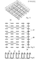
- FIG. 9 to 11 represent a third embodiment of the drawer element, in which push brackets 37 are fastened on longitudinal connecting rods 38 crossing them, which in turn are connected and held together by cross-connecting rods 39.
- the distances between the push handle legs can be kept the same lengthways and crossways.
Abstract
Description
Die Erfindung betrifft ein Schubbewehrungssystem zur Gewährleistung der Tragfähigkeit querkraftbeanspruchter Zonen von Stahlbetonplatten, insbesondere durchstanzgefährdeter Zonen von Flachdecken mit je einer darin eingeschlossenen unteren und oberen, parallel zur Flachdecke verlaufenden Bewehrung aus mindestens je einer Bewehrungslage.The invention relates to a shear reinforcement system to ensure the load-bearing capacity of zones of reinforced concrete plates that are subject to shear forces, in particular zones of flat slabs that are at risk of punching, each with a lower and upper reinforcement included therein, running parallel to the flat slab and comprising at least one reinforcement layer.
Ein allgemein geläufiges Beispiel für eine derart beanspruchte Stahlbetonplatte ist die Flachdecke über einem ausgedehnten, unterirdischen Einstellraum für Kreftfahrzeuge, auf der sich ein Parkplatz befindet, und die ringsum auf Wänden, dazwischen jedoch auf einer Stütze oder deren Mehrzahl ruht. Am Umfang längs den Wänden wirkt auf die Decke eine Querkraftbeanspruchung, eine weit größere jedoch am viel kleineren Umfang einer Stütze. Im Bereich des Stützenquerschnitts wirkt auf die Decke eine nach oben gerichtete Querkraft, unmittelbar außerhalb dieses Bereiches jedoch eine abwärts gerichtete Kraft gleichen Betrages aus dem Gewicht der Decke und ihrer Last, d.h. längs des Stützenumfanges ist die Decke auf Abscheren und in der umgebenden Zone stark auf Biegung beansprucht, was bekanntlich eine bei Beton sehr ungünstige Beanspruchungsart ist. So entsteht die Gefahr, daß dort die Decke durchgestanzt wird.A common example of such a reinforced concrete slab is the flat ceiling above an extensive underground parking space for commercial vehicles, on which there is a parking lot, and which rests all around on walls, but between them on a support or the majority thereof. On the circumference along the walls, a shear load acts on the ceiling, but a much larger one on the much smaller circumference of a column. In the area of the column cross section, an upward transverse force acts on the ceiling, but immediately outside this area there is a downward force of the same amount from the weight of the ceiling and its load, i.e. along the circumference of the column, the ceiling is severely sheared and in the surrounding zone Bend claims what is known to be a very unfavorable type of stress in concrete. This creates the danger that the ceiling will be punched through there.
Um dies auszuschließen, hat man bisher derart gefährdete Zonen von Stahlbetonplatten, z.B. Flachdecken, mit einer überaus komplexen und dichten Stahlarmierung versehen, etwa bestehend aus in Längs- und Querrichtung einander kreuzenden unteren und oberen Bewehrungslagen, verbunden durch zahllose einzelne sog. Schubbügel, deren Placierung und Befestigung überaus kritisch ist, und beim Aufbau muβ man für gewöhnlich Distanzierungs-Vorrichtungen zu Hilfe nehmen und kann man die Bewehrungsstäbe wenigstens teilweise u.U. nur der Länge nach einschieben. Man braucht dazu geübte und kundige, gewissenhaft arbeitende Fachkräfte, eine genaue Kontrolle aller Details durch den Baustatiker ist unerläplich, und so ist die Herstellung einer derartigen Armierung auf der Baustelle äußerst zeitraubend und kostspielig, während die Gefahr von Fehlern nicht ganz auszuschließen geht.In order to rule this out, zones of reinforced concrete slabs, e.g. Flat ceilings, provided with an extremely complex and dense steel reinforcement, e.g. consisting of lower and upper reinforcement layers crossing one another in the longitudinal and transverse directions, connected by countless individual so-called push bars, the placement and fastening of which is extremely critical, and when assembling you usually have to do spacing -Devices to help and you can at least partially the reinforcement bars just insert lengthways. You need trained and knowledgeable, conscientiously working specialists, a precise control of all details by the structural engineer is impossible, and so the production of such a reinforcement on the construction site is extremely time-consuming and expensive, while the risk of errors cannot be completely ruled out.
Die Erfindung schafft hierin Abhilfe, indem sie auf dem Gedanken eines Schubbewehrungssystems beruht, das anstelle einzelner Schubbügel ein fertig vorfabriziertes, daher kostengünstiges und aus Serienherstellung ohne weiteres fehlerfreies Schubkorbelement oder dessen Mehrzahl enthält, und das besondere Distanzierungsmaßnahmen, Längs-Einschieben und andere Komplikationen erübrigt. Im einzelnen ist das neue Schubbewehrungssystem durch die folgenden Merkmale gekennzeichnet:
- a] Wenigstens in der am meisten beanspruchten und gefährdeten Zone ist ein Schubkorbelement, das sich aus der unteren bis in die obere Bewehrung erstreckt, oder eine Kombination aus mehreren solchen Schubkorbelementen angeordnet;
- b] das Schubkorbelement besteht aus U-förmigen Schubbügeln, deren in Querkraftrichtung, bei horizontalen Flachdecken somit nach oben weisende Schenkel an ihren Enden hakenartig abgebogen sind, und aus Verbindungsstäben, die mit den sie kreuzenden Schubbügeln an den Kreuzungsstellen fest verbunden sind;
- c] hierbei ist die Form und die gegenseitige Lage der Schubbügel und der Verbindungsstäbe so gewählt, daß das Schubkorbelement ein zusammenhängendes Ganzes bildet;
- d] das Schubkorbelement liegt unmittelbar auf der untersten Bewehrungslage, während die Stäbe der oberen Bewehrung, welche das Schubkorbelement quer zu den hakenartig abgebogenen Schubbügelenden kreuzen, in die jeweils in der Flucht der Stäbe liegenden Schubbügelenden eingelegt sind;
- e] demgemäß ist die Höhe der Schubbügel gewählt, so daß die statisch richtige Lage der oberen Bewehrung schon ohne Verlegen einer Distanzhaltevorrichtung für die obere Bewehrung gegenüber der unteren Schalung gewährleistet ist.
- a] At least in the most stressed and vulnerable zone there is a drawer element that extends from the lower to the upper reinforcement, or a combination of several such drawer elements;
- b] the push cage element consists of U-shaped push bars, the legs of which, in the transverse direction, with horizontal flat ceilings thus pointing upward at their ends, are bent like hooks, and of connecting rods which are fixed at the crossing points with the push bars crossing them are connected;
- c] Here, the shape and the mutual position of the push bracket and the connecting rods is chosen so that the push basket element forms a coherent whole;
- d] the push cage element lies directly on the lowest reinforcement layer, while the bars of the upper reinforcement, which cross the push cage element transversely to the hook-like bent thrust bar ends, are inserted into the push bar ends which are in alignment with the bars;
- e] accordingly, the height of the push bracket is selected so that the statically correct position of the upper reinforcement is guaranteed even without laying a spacer device for the upper reinforcement relative to the lower formwork.
Für gewöhnlich werden als untere und als obere Bewehrung je zwei einander in Längs- und Querrichtung kreuzende Bewehrungslagen aus den bekannten Armierungsstäben vorgesehen. Dann stellt man das neue Schubkorbelement einfach auf die unterste Bewehrungslage - z.B. so, daß seine Verbindungsstäbe auf den Stäben dieser Bewehrungslage stehen, während die Schubbügel in sie hineinreichen, sofern die Verbindungsstäbe oberhalb der Schubbügelstege verlaufen -; es ist dann vorteilhaft, die zweite, die unterste kreuzende Lage der unteren Bewehrung im Bereich des Schubkorbelements in dessen Schubbügel einzulegen. Bei den Stäben der unteren Lage der oberen Bewehrung entfällt jegliches Einschieben, sie sind sodann lediglich in die hakenartig abgebogenen Schubbügelenden einzulegen und festzumachen, vom Schubkorbelement ohne weiteres richtig distanziert, sonstigen Anordnungsfehlern ist ebenfalls vorgebeugt, und zuletzt wird die oberste Bewehrungslage aufgelegt, ebenfalls ohne weiteres richtig angeordnet. Dank der Erfindung wird mithin unter Vereinfachung und Verbilligung ein wesentlicher Fortschritt erzielt.Usually, two reinforcement layers from the known reinforcing bars crossing each other in the longitudinal and transverse directions are provided as the lower and upper reinforcement. Then you simply place the new drawer element on the lowest reinforcement layer - e.g. such that its connecting rods stand on the rods of this reinforcement layer, while the push bars reach into them, provided that the connecting rods run above the push bar webs; it is then advantageous to insert the second, the lowest crossing position of the lower reinforcement in the area of the push cage element in its push bracket. With the bars of the lower layer of the upper reinforcement, there is no need to push them in; they are then only to be inserted and fastened in the hook-like bent ends of the push handle, easily separated from the push element, other arrangement errors are also prevented, and finally the top reinforcement layer is placed, also without further ado arranged correctly. Thanks to the invention, significant progress is thus achieved with simplification and cost-effectiveness.
Einige Ausführungsformen des neuen Schubbewehrungssystems haben das gemeinsame Merkmal, daß die Verbindungsstäbe unmittelbar über und/oder unter den Stegen der Schubbügel in einem gegenseitigen Abstand einander parallel verlaufen, der kleiner als die Schubbügelbreite ist, und daß die Schubbügel quer zu den Verbindungsstäben stehen und längs diesen, wenigstens soweit es sich nicht um die äußeren beiderseits handelt, derart abwechselnd seitlich versetzt angeordnet sind, daß sie mindestens je zwei Verbindungsstäbe kreuzen und dank der Anordnung und fester Verbindung an den Kreuzungsstellen eine feste Verbindung sämtlicher Verbindungsstäbe miteinander bewirken, so daß das Schubkorbelement insgesamt ein zusammenhängendes Ganzes bildet.Some embodiments of the new push reinforcement system have the common feature that the connecting rods directly above and / or under the webs of the push bar in a mutual distance parallel to each other, which is smaller than the push bar width, and that the push bars are perpendicular to the connecting rods and along these, at least insofar as it is not the outer on both sides, so alternately laterally offset that they are at least two each Cross connecting rods and, thanks to the arrangement and firm connection at the intersection points, bring about a firm connection of all connecting rods with one another, so that the drawer element as a whole forms a coherent whole.
Bei der einen dieser Ausführungsformen weisen die Schubbügel in Richtung der Verbindungsstäbe reihenweise wenigstens annähernd gleichmäßige Abstände auf und sind sie längs eines der Verbindungsstäbe derart seitlich versetzt angeordnet, daß sie abwechselnd diesen und den links benachbarten Verbindungsstab, diesen und den rechts benachbarten Verbindungsstab, sowie die beiden links und rechts benachbarten Verbindungsstäbe, dann jedoch nicht den betreffenden Verbindungsstab selber kreuzen und fest damit verbunden sind.In one of these embodiments, the push bars in the direction of the connecting rods are at least approximately evenly spaced in rows and they are laterally offset along one of the connecting rods in such a way that they alternate between this and the adjacent connecting rod on the left, this and the adjacent connecting rod on the right, and the two left and right adjacent connecting rods, but then do not cross the relevant connecting rod itself and are firmly connected to it.
Von Bedeutung sind drei Varianten hiervon. Zur Materialersparnis kann mindestens ein Teil der Verbindungsstäbe dort unterbrochen sein, wo Schubbügel die je zwei links und rechts benachbarten Verbindungsstäbe, nicht jedoch den betreffenden Verbindungsstab kreuzen.Three variants of this are important. To save material, at least some of the connecting rods can be interrupted where push bars cross the two connecting rods on the left and right, but not the connecting rod in question.
Bei weiteren zwei dieser Varianten geht es um dieMöglichkeit, benachbart angeordnete Schubkorbelemente so aneinandersetzen zu können, daß insgesamt die Struktur gleichmäßig bleibt, Die eine dieser Varianten besteht darin, daß die Schubbügel gleiche Breite aufweisen, und daß längs des einen äußeren Verbindungsstabes nur diejenigen ihn kreuzenden, fest mit ihm verbundenen Schubbügel vorgesehen sind, welche diesen und den nächstinneren Verbindungsstab kreuzen, während der andere äußere Verbindungsstab derart vollständig mit ihn kreuzenden, fest mit ihm verbundenen Schubbügeln bestückt ist, als befinde sich außerhalb von ihm ein weiterer Verbindungsstab. Auf diese Weise kann man zwei solche Schubkorbelemente ohne zusätzliche Teile auf einfache Weise fest miteinander verbinden, indem man. die vom einen Schubkorbelement aufs andere übergreifenden Schubbügel mit des letzteren Verbindungsstäben z.B. verschweißt. Die andere dieser Varianten wahrt die Gleichmäßigkeit der Struktur beim Zusammensetzen zweier oder mehrerer Schubkorbelemente dadurch, daß mindestens längs des einen äußeren Verbindungsstabes abwechselnd Schubbügel von voller Breite vorgesehen sind, welche den äußeren und den nächstinneren Verbindungsstab kreuzen und fest damit verbunden sind, und Schubbügel von geringerer, z.B. halber Breite, welche nur den äußeren Verbindungsstab kreuzen und fest damit verbunden sind.Another two of these variants deal with the possibility of being able to place adjacent push basket elements in such a way that the overall structure remains uniform. One of these variants is that the push handles have the same width and that only those crossing the outer connecting rod are those , pushrods firmly connected to it are provided, which cross this and the next inner connecting rod, while the other outer connecting rod is completely equipped with crossing pushrods that are firmly connected to it, as if there was another connecting rod outside of it. In this way you can have two such drawer elements easily connect to each other without additional parts by using. which, for example, is welded from one drawer element to the other overlapping push bracket with the latter connecting rods. The other of these variants maintains the uniformity of the structure when assembling two or more push cage elements in that push bars of full width are alternately provided at least along one outer connecting bar, which push bars cross the outer and the next inner connecting bar and are firmly connected thereto, and push bars of less , eg half width, which only cross the outer connecting rod and are firmly connected to it.
Eine weitere Ausführungsform mit dem zuvor genannten gemeinsamen Merkmal ist so ausgebildet, daß der Abstand von Schubbügel zu Schubbügel in Richtung der Verbindungsstäbe abwechselnd gleich einem konstanten Wert und gleich Null ist, und daß im letzteren Falle die beiden aneinander liegenden, ein Schubbügelpaar bildenden Schubbügel 33 derart seitlich gegeneinander versetzt sind, daß sich ein Schenkel des einen in der Mitte zwischen den Schenkeln des anderen befindet. Hierbei werden jeweils gleiche Abstände der Schubbügelschenkel in der Längsrichtung und in der Querrichtung ermöglicht, worauf weiter unten näher eingegangen wird.Another embodiment with the aforementioned common feature is designed so that the distance from push bar to push bar in the direction of the connecting rods is alternately equal to a constant value and zero, and that in the latter case the two
Die letztere Möglichkeit besteht auch bei einer anderen, vorteilhaften Ausführungsform dadurch, daß als Verbindungsstäbe Längsverbindungsstäbe und Querverbindungsstäbe vorgesehen sind, die je für sich in einem Abstand von Stab zu Stab etwa gleich der doppelten Schubbügelbreite einander parallel verlaufen, sich gegenseitig rechtwinklig kreuzen und an ihren Kreuzungsstellen fest miteinander verbunden sind, und daß quer zu jedem Längsverbindungsstab Schubbügel angeordnet sind, den sie in der Mitte ihres Steges kreuzen, wo sie fest mit ihm verbunden sind. Es ist dann zweckmäßig, die Schubbügel auf den Längsverbindungsstäben etwa in der Mitte zwischen den Querverbindungsstäben anzuordnen. Dies ist also eine sehr regelmäßige Anordnung: In Längsrichtung und in Querrichtung fluchten die einzelnen Schubbügel miteinander. Verbindungsstäbe haben sie nicht miteinander zu verbinden, sondern diesem Zweck dienen separat die Querverbindungsstäbe,The latter possibility also exists in another, advantageous embodiment in that longitudinal connecting rods and cross connecting rods are provided as connecting rods, each of which runs parallel to one another at a distance from rod to rod approximately equal to twice the push bar width, cross each other at right angles and at their crossing points are firmly connected to each other, and that push bars are arranged transversely to each longitudinal connecting rod, which they cross in the middle of their web, where they are firmly connected to it. It is then expedient to arrange the push bars on the longitudinal connecting rods approximately in the middle between the transverse connecting rods. So this is a very regular arrangement: the individual push bars are aligned with each other in the longitudinal and transverse directions. They do not have to connect connecting rods, but the cross-connecting rods serve this purpose separately,
Eine Variante hiervon besteht darin, daß als Verbindungsstäbe Längs- und Querverbindungsstäbe vorgesehen sind, die je für sich in einem Abstand von Stab zu Stab gleich der Schubbügelbreite verlaufen, sich gegenseitig rechtwinklig kreuzen und an ihren Kreuzungsstellen fest miteinander verbunden sind, und daß die Schubbügel quer auf je zwei benachbarten Längsverbindungsstäben stehen und sie am unteren Ende ihrer Schenkel kreuzen, wo sie fest mit ihnen verbunden sind. Die gegenüber dem Vorigen kleineren Abstände zwischen den Verbindungsstäben sowie die zusätzliche Verbindung je zweier Stäbe durch die Schubbügel führt natürlich zu größerer Stabilität des gesamten Schubkorbelements; hierbei ist zunächst daran gedacht, die Schubbügel so regelmäßig wie bei der vorigen Anordnung anzubringen, d.h. derart, daß sie jeweils in Längs- und Querrichtung miteinander fluchten, und die Schubbügelschenkel können auch hierbei in beiden Richtungen gleiche Abstände erhalten.A variant of this is that longitudinal and transverse connecting rods are provided as connecting rods, each of which is at a distance from rod to rod equal to the push bar width, cross each other at right angles and is firmly connected to one another at their crossing points, and that the push bar is transverse stand on two adjacent longitudinal connecting rods and cross them at the lower end of their legs, where they are firmly connected to them. The smaller distances between the connecting rods compared to the previous one, as well as the additional connection of two rods by the push bar, naturally lead to greater stability of the entire push basket element; The first step here is to attach the push bars as regularly as in the previous arrangement, i.e. such that they are aligned with each other in the longitudinal and transverse directions, and the thrust arm legs can also be given equal distances in both directions.
Bei dieser Variante kann man sich auch darauf beschränken, anstelle der Schubbügel nur deren Schenkel vorzusehen; allerdings sollten diese dann mit den Längs- oder Querverbindungsstäben oder mit ihren Kreuzungspunkten solide verbunden, nicht bloß geheftet werden. Eine Verbindung an den Kreuzungspunkten kann man u.a. dadurch herstellen, daß man eine Rohrarmatur aus drei aufeinander senkrecht stehenden Rohrstücken verwendet und dem Längs- und Querverbindungsstab sowie den Schubbügelschenkel einführt, um sie darin zu verkleben, z.B. mit einem Epoxydharz mit Härter oder mit einem Cyanoacrylat.In this variant, you can also restrict yourself to providing only the legs of the push bars; however, these should then be solidly connected to the longitudinal or transverse connecting rods or to their crossing points, not simply tacked. A connection at the crossing points can be e.g. Manufacture by using a pipe fitting consisting of three mutually perpendicular pieces of pipe and inserting the longitudinal and transverse connecting rod as well as the push bracket leg in order to glue them, e.g. with an epoxy resin with hardener or with a cyanoacrylate.
Man kann da jedoch statt dessen die Schubbügel auch seitlich versetzt anordnen, derart daß sie längs eines Längsverbindungsstabes diesen abwechselnd mit dem links und mit dem rechts benachbarten verbinden. Dann können die Querverbindungsstäbe auch weggelassen werden.However, one can instead arrange the push bars laterally offset, so that they alternately connect this along a longitudinal connecting rod with the one on the left and the one on the right. Then the cross-connecting rods can also be omitted.
Generell ist es von Vorteil, wenn die Enden der Schenkel der Schubbügel hakenartig um wenigstens annähernd 180° derart abgebogen sind, daß Stäbe der oberen Bewehrung in die hakenartigen Abbiegungen einlegbar sind, und daß die Schubbügel zum gleichen Zweck so ausgerichtet sind, daß die hakenartigen Abbiegungen reihenweise miteinander fluchten.Generally it is advantageous if the ends of the legs the push bars are hook-like bent by at least approximately 180 ° in such a way that bars of the upper reinforcement can be inserted into the hook-like bends, and that the push bars are aligned for the same purpose so that the hook-like bends are aligned with one another in rows.
Bei einigen der beschriebenen Ausführungsformen wurde erwähnt, daß die Schenkel der Schubbügel in der Längsrichtung und in der Querrichtung jeweils gleiche Abstände voneinander haben können. Die Bügelschenkeldichte ist dann isotrop. Dies ist dann von Vorteil, wenn die Querkraft in beiden Richtungen etwa gleich bzw. rund um die Stütze annähernd konstant ist. Ein weiterer Vorteil besteht darin, daß man bei großen Querkräften entsprechend kleine Bügelschenkel-Abstände wählen kann, ohne in einer Richtung zwangsläufig noch kleinere in Kauf nehmen zu müssen, was sich in einer entsprechenden Materialersparnis auswirkt. Allerdings sind die anderen Ausführungsformen mit grundsätzlich anisotroper Bügelschenkeldichte dann am Platze, wenn in Längs- und Querrichtung verschieden große Querkräfte vorgegeben sind; freilich muß man solche Schubkorbelemente dann auf der Baustelle richtig - nicht etwa um 90° verdreht - anordnen, d.h. sie sind dann nicht ohne weiteres narrensicher.In some of the described embodiments, it was mentioned that the legs of the push bars can each have the same distances from one another in the longitudinal direction and in the transverse direction. The arm leg density is then isotropic. This is advantageous if the transverse force is approximately the same in both directions or approximately constant around the support. Another advantage is that with large transverse forces you can choose correspondingly small stirrup leg distances without necessarily having to accept smaller ones in one direction, which results in a corresponding saving in material. However, the other embodiments with a fundamentally anisotropic stirrup leg density are in place when transverse forces of different magnitudes are specified in the longitudinal and transverse directions; of course such drawer elements must then be correctly arranged on the construction site - not rotated by 90 °, i.e. then they are not easily foolproof.
In speziellen Anwendungsfällen kann es von Vorteil sein, wenn die Verbindungsstäbe oder die Längsverbindungsstäbe und/ oder die Querverbindungsstäbe im Bereich der Ränder des Schubkorbelements einen geringeren gegenseitigen Abstand aufweisen als inmitten, und/oder daß Querverbindungsstäbe zusätzlich zu den Längsverbindungsstäben nur in den betreffenden Randbereichen vorgesehen sind. Man kann dann von Stabilisierungs- oder Versteifungsstäben im Randbereich sprechen, die das gesamte Schubkorbelement insbesondere widerstandsfähiger gegen Verwerfungen machen.In special applications it can be advantageous if the connecting rods or the longitudinal connecting rods and / or the transverse connecting rods have a smaller mutual distance in the area of the edges of the drawer element than in the middle, and / or that transverse connecting rods are only provided in the relevant edge areas in addition to the longitudinal connecting rods . One can then speak of stabilizing or stiffening bars in the edge area, which make the entire drawer element in particular more resistant to warping.
Die beschriebenen Ausführungsformen legen dem Fachmann weitere nahe, einschließlich solcher, wo das Schubkorbelement nicht, wie meistens verwendet, im Grundriß rechteckig oder quadratisch ist, sondern eine solche Form aufweist, daß es einem Parallelogramm, Kreis oder Kreissektor einbeschreibbar ist. Dabei können die Verbindungsstäbe parallel zwei einander gegeüberliegenden Parallelogrammseiten verlaufen bzw. radial angeordnet sein.The described embodiments suggest others to those skilled in the art, including those where the drawer element is not, as is most often used, rectangular or in plan is square, but has such a shape that it can be inscribed in a parallelogram, circle or circle sector. The connecting rods can run parallel to two mutually opposite parallelogram sides or be arranged radially.
Schließlich ist noch das Material zu erwähnen, aus dem das Schubkorbelement hergestellt ist, weil es immerhin an Stellen höchster Beanspruchung eine für die Festigkeit und Lebensdauer eines Bauwerkes entscheidende Rolle spielte Ist die Lebensdauer wenigstens auf lange Sicht kein entscheidender Gesichtspunkt oder nach Meinung des Bauherrn neben den Kosten belanglos, so kann das Schubkorbelement in der bei Armierungsteilen seit langem üblichen Weise aus gewöhnlichem Armierungsstahl bestehen.Finally, the material from which the drawer element is made is worth mentioning, because it plays a crucial role in the strength and durability of a building in places of high stress. E At least in the long term, the durability is not a decisive factor or, in the opinion of the owner, besides irrelevant of the costs, the drawer element can consist of ordinary reinforcing steel in the way that has long been common for reinforcement parts.
Nun gibt es neben dem bekannteren "Waldsterben" heute freilich eine analoge, nämlich auf der gleichen Ursache, der Luftverschmutzung beruhende Erscheinung, die man "Betonsterben" nennen könnte. Schwefeldioxyd und Stickoxyde bilden mit der in der Luft stets vorhandenen, aber auch im Beton enthaltenen Feuchtigkeit Säuren, diese durchdringen den bei weitem nicht diffusionsdichten Beton im Laufe der Zeit, gelangen dadurch an die Armierung und korrodieren diese, wodurch das Volumen der Armierungsstäbe wächst und sie schließlich den umgebenden Beton sprengen. Bei der besonders großen Armierungsdichte mit Schubbügeln usw. im Bereich der durchstanzgeFährdeten Zonen von Stahlbetonplatten ist dort die Gefahr eines Sprengens des Betons besonders groß bzw. ist um so früher damit zu rechnen.Now, in addition to the better-known "forest dieback", there is of course an analogous phenomenon, namely that of the same cause, air pollution, which could be called "concrete dieback". Sulfur dioxide and nitrogen oxides form with the moisture that is always present in the air, but also contained in the concrete, which penetrate the by far not diffusion-proof concrete over time, thereby reaching the reinforcement and corroding it, which increases the volume of the reinforcing bars and they finally blow up the surrounding concrete. Given the particularly high reinforcement density with push bars, etc. in the area of the zones of reinforced concrete slabs that are at risk of punching, the risk of the concrete exploding is particularly high there or is to be expected all the sooner.
Zur Abhilfe wurde bisher eine dickere Betonüberdeckung und ein höherer Zementgehalt des Betons vorgeschlagen, jedoch kann dies die Schäden nur etwas verzögern, denn jene Schadstoffe durchdringen schließlich auch eine dickere poröse Schicht, und deren höherer Alkaligehalt wird infolge der ständigen Beaufschlagung mit den sauren Schadstoffen schließlich ebenfalls neutralisiert. Die auch schon vorgeschlagene Verzinkung der Armierungsteile ist, entgegen immer noch weit verbreiteter Meinung, gegen jene Schadstoffe nicht beständig und kann die Schäden daher nur geringfügig verzögern.A thicker concrete cover and a higher cement content of the concrete have been proposed to remedy this, but this can only delay the damage somewhat, because those pollutants eventually penetrate a thicker porous layer, and their higher alkali content is finally also due to the constant exposure to the acidic pollutants neutralized. Contrary to widespread opinion, the galvanizing of the reinforcement parts that has already been proposed is not resistant to these pollutants and can therefore only delay the damage slightly.
Um jener Korrosion bleibend vorzubeugen, schlägt der Erfinder vor, daß das Schubkorbelement aus glattem oder mindestens teilweise profiliertem Rundstahl, der mit einem korrosionsbeständigen und diffusionsdichten Kunststoff beschichtet ist, oder aus rostfreiem Stahl besteht. Die Tauglichkeit des letzteren steht außer Frage, und die höheren Kosten stehen in keinem Verhältnis zu den Schäden, die er verhütet. Zwar wird rostfreier Stahl von gewissen Säuren, wenn sie stark verdünnt sind und daher einen hohen Dissoziationsgrad aufweisen, in gewisser Weise angegriffen, aber dies äußert sich lediglich in einer oberflächlichen Verfärbung, mit der keine merkliche Volumenzunahme einhergeht.In order to prevent this corrosion permanently, the inventor suggests that the drawer element be made of smooth or at least partially profiled round steel, which is coated with a corrosion-resistant and diffusion-tight plastic, or of stainless steel. The suitability of the latter is beyond question and the higher costs are disproportionate to the damage it prevents. Certain acids, to a certain extent, are attacked by certain acids if they are very dilute and therefore have a high degree of dissociation, but this is only manifested by a surface discoloration, which is not accompanied by a noticeable increase in volume.
Für die Kunststoffbeschichtung kommt nicht etwa ein lösungsmittelhaltiger Lack od.dgl. in Betracht, denn nach dem Verdunsten des Lösungsmittels wäre die Schicht nicht diffusionsdicht. Übliche Zweikomponenten-Harz-Härter-Gemische werden beim Härten unter Schrumpfung sehr hart, Überzüge daraus werden deshalb rissig und daher nutzlos. Mischt man ihnen einen Weichmacher bei, so sind sie dann nicht diffusionsdicht und also für den vorliegenden Zweck ebenfalls nutzlos. Der Vorschlag betrifft daher zunächst die Verwendung von Bisphenol-A-Epichlorhydrin als Harz und ein tertiäres Amin aus sehr langen Kettenmolekülen als Härter, z.B. Cocosamin; nach dem Aushärten ist dies schon ohne Weichmacher hinreichend elastisch, so daß es als Überzug keine Risse bildet, sowie perfekt diffusionsdicht selbst gegenüber den kleinsten Molekülen, und zudem ist dies einer der wenigen Kunststoffe, die gegenüber jenen Schadstoffen bleibend beständig sind. Dies schließt allerdings nicht aus, daß noch weitere Kunststoffe mit für den vorliegenden Zweck geeigneten Eigenschaften gefunden werden.For the plastic coating is not a solvent-based paint or the like. into consideration, because after the solvent has evaporated, the layer would not be diffusion-tight. Usual two-component resin-hardener mixtures become very hard when hardening with shrinkage, coatings from them therefore become cracked and therefore useless. If you add a plasticizer to them, they are then not diffusion-proof and therefore also useless for the present purpose. The proposal therefore initially relates to the use of bisphenol-A-epichlorohydrin as a resin and a tertiary amine from very long chain molecules as a hardener, e.g. Cocosamine; after curing, this is sufficiently elastic even without a plasticizer, so that it does not form any cracks as a coating, and is perfectly diffusion-tight even against the smallest molecules, and it is also one of the few plastics that are permanently resistant to those pollutants. However, this does not exclude that other plastics with properties suitable for the present purpose are found.
Es liegt auf der Hand, daß beide Maßnahmen, die Verwendung von rostfreiem Stahl für diese spezielle Aufgabe und erst recht die Kunststoffbeschichtung, auf der Baustelle nicht praktikabel wären. So ist der Vorteil der Erfindung nicht gering einzuschätzen, daß sie dank der Vorfabrikation des Schubkorbelements - also für die am meisten durch jenes Betonsprengen gefährdete Stelle - problemlos die Möglichkeit bietet, die eine oder andere dieser Maßnahmen zu treffen,It is obvious that both measures, the use of stainless steel for this special task and especially the plastic coating, would not be practical on the construction site. This is the advantage of the invention not to be underestimated that thanks to the prefabrication of the drawer element - that is to say for the area most at risk from that concrete blasting - it easily offers the possibility of taking one or the other of these measures,
Die beigefügten Zeichnungen veranschaulichen die Erfindung anhand einiger Ausführungsbeispiele.The accompanying drawings illustrate the invention using some exemplary embodiments.
Fig.1 zeigt auf einer Stütze 1, die mit einem fett gezeichneten Quadrat angedeutet ist, einen Ausschnitt aus einer Flachdecke 2, während das neue Schubbewehrungssystem darin andeutungsweise mit vier zusammengesetzten Schubkorbelementen 3 oder einem entsprechend größeren, sowie mit in Längsrichtung verlaufenden unteren und oberen Bewehrungslagen 4, 4' und in Querrichtung verlaufenden unteren und oberen Bewehrungslagen 5, 5" dargestellt ist. Faßt man Fig.1 als Ansicht von oben auf, so ist Fig.2 der von der unteren Blattkante her gesehene Schnitt durch die Stütze 1 derselben Anordnung in größerem Maßstab; dort kehren bei den gleichen Teilen die gleichen Bezugszeichen wieder. Die Darstellung des Schubkorbelements 3 in Fig.2 konnte zwar nur einer konkreten Ausführungsform entsprechen - gewählt wurde diejenige von Fig.9 bis 11 -, ist aber nicht speziell zu verstehen, weshalb hier auch alle Teile des Schubkorbelements , allgemein gemäß der Erfindung gemeint, einheitlich mit 3 bezeichnet sind.Fig.1 shows on a
Eine erste Ausführungsform des Schubkorbelements ist in den Fig.3 bis 5 dargestellt; in Fig.3 in Ansicht von oben, in Fig.4 in Seitenansicht aus der in Fig.3 unten befindlichen Richtung, in Fig.5 zur Veranschaulichung in perspektivischer Darstellung. Der gegenseitige Abstand von Verbindungsstäben 32 ist kleiner als die Breite von Schubbügeln 30, deren jeder mit den zwei ihn kreuzenden Verbindungsstäben 32 fest verbunden ist, während schmalere Schubbügel 31 am Rand für einen vergleichmäßigten Abschluß sorgen.A first embodiment of the drawer element is shown in Figures 3 to 5; in Figure 3 in top view, in Figure 4 in side view from the direction in Figure 3 below, in Figure 5 for illustration in perspective. The mutual distance from connecting
In gleicher Anordnung und Darstellungsweise stellen die Fig.6 bis 8 eine zweite Ausführungsform des Schubkorbelements dar. Auch hier ist der gegenseitige Abstand von Verbindungsstäben 35 kleiner als die Breite von sie kreuzenden Schubbügeln 33, deren jeder zwei Verbindungsstäbe kreuzt und fest damit verbunden ist; der gegenseitige Abstand der Schubbügel 33 in Richtung der Verbindungsstäbe 35 ist jedoch abwechselnd gleich einem konstanten Wert und gleich Null, während die Schenkel der Schubbügel in dieser Richtung und quer hierzu gleiche Abstände aufweisen. Am Rande sorgen schmalere Schubbügel 34 für einen vergleichmäßigten Abschluß und sind die Verbindungsstäbe 35 in kleinerem Abstand sowie Querverbindungsstäbe 36 zur Versteifung des Schubkorbelements vorgesehen.6 to 8 represent a second embodiment of the push cage element in the same arrangement and manner of representation. Here, too, the mutual spacing of connecting
In ebenfalls gleicher Anordnung und Darstellungsweise stellen die Fig.9 bis 11 eine dr itte Ausführungsform des Schubkorbelements dar, bei welcher Schubbügel 37 auf sie kreuzenden Längsverbindungsstäben 38 befestigt sind, die ihrerseits durch Querverbindungsstäbe 39 verbunden und zusammengehalten sind. Auch hier können, wie gezeichnet, die Abstände der Schubbügelschenkel längs und quer gleich gehalten sein.9 to 11 represent a third embodiment of the drawer element, in which push
Claims (16)
gekennzeichnet durch die folgenden Merkmale:
characterized by the following features:
Priority Applications (1)
| Application Number | Priority Date | Filing Date | Title |
|---|---|---|---|
| AT85810587T ATE65817T1 (en) | 1984-12-12 | 1985-12-11 | SHEAR REINFORCEMENT SYSTEM. |
Applications Claiming Priority (2)
| Application Number | Priority Date | Filing Date | Title |
|---|---|---|---|
| CH5910/84 | 1984-12-12 | ||
| CH591084 | 1984-12-12 |
Publications (3)
| Publication Number | Publication Date |
|---|---|
| EP0184995A2 true EP0184995A2 (en) | 1986-06-18 |
| EP0184995A3 EP0184995A3 (en) | 1988-08-31 |
| EP0184995B1 EP0184995B1 (en) | 1991-07-31 |
Family
ID=4301373
Family Applications (1)
| Application Number | Title | Priority Date | Filing Date |
|---|---|---|---|
| EP85810587A Expired - Lifetime EP0184995B1 (en) | 1984-12-12 | 1985-12-11 | Reinforcement system preventing shearing |
Country Status (3)
| Country | Link |
|---|---|
| EP (1) | EP0184995B1 (en) |
| AT (1) | ATE65817T1 (en) |
| DE (1) | DE3583662D1 (en) |
Cited By (10)
| Publication number | Priority date | Publication date | Assignee | Title |
|---|---|---|---|---|
| EP0414484A1 (en) * | 1989-08-21 | 1991-02-27 | Square Grip Limited | Shearhead reinforcement |
| GB2235226A (en) * | 1989-08-21 | 1991-02-27 | Square Grip Ltd | Shearhead |
| EP0781891A1 (en) * | 1995-12-30 | 1997-07-02 | Ancotech Ag | Reinforcement for columns supported slab floors, shear-reinforcing element as well as a method for manufacturing a reinforcement |
| WO1997036067A1 (en) * | 1996-03-26 | 1997-10-02 | Sicon S.R.O. | Joint of concrete building elements |
| GB2328455A (en) * | 1996-08-21 | 1999-02-24 | Jubin Motamed | Concrete slab shear reinforcement |
| DE10312181A1 (en) | 2003-03-19 | 2004-09-30 | Spannverbund Gesellschaft für Verbundträger mbH | Roof pillar and reinforced concrete roof combination for e.g. building, includes roof pillar having steel mushroom shape section which provides additional shear reinforcement to covering |
| WO2005003482A1 (en) * | 2003-07-01 | 2005-01-13 | Onesteel Reinforcing Pty Ltd | A reinforcing component |
| WO2011067027A1 (en) * | 2009-12-03 | 2011-06-09 | Fischer Rista Ag | Reinforcement device |
| ITMI20100357A1 (en) * | 2010-03-05 | 2011-09-06 | Pigazzi Reti S R L | PUNCHING REINFORCEMENT ELEMENTS - CUTTING FOR REINFORCED CEMENT PLATES |
| WO2022058695A1 (en) * | 2020-09-21 | 2022-03-24 | Ecole Nationale Des Ponts Et Chaussees | Reinforcing cage for strengthening a concrete beam |
Families Citing this family (1)
| Publication number | Priority date | Publication date | Assignee | Title |
|---|---|---|---|---|
| CH701682A1 (en) | 2009-08-21 | 2011-02-28 | Sybaco Ag | Studrails. |
Citations (2)
| Publication number | Priority date | Publication date | Assignee | Title |
|---|---|---|---|---|
| AT331469B (en) * | 1974-06-26 | 1976-08-25 | Hofstadter Dipl Ing Erich | REINFORCEMENT |
| EP0143101A2 (en) * | 1983-08-26 | 1985-05-29 | BEST - Baueisen- und Stahl-Bearbeitungsgesellschaft m.b.H. | Reinforcement for reinforced concrete constructions |
-
1985
- 1985-12-11 EP EP85810587A patent/EP0184995B1/en not_active Expired - Lifetime
- 1985-12-11 DE DE8585810587T patent/DE3583662D1/en not_active Expired - Lifetime
- 1985-12-11 AT AT85810587T patent/ATE65817T1/en not_active IP Right Cessation
Patent Citations (2)
| Publication number | Priority date | Publication date | Assignee | Title |
|---|---|---|---|---|
| AT331469B (en) * | 1974-06-26 | 1976-08-25 | Hofstadter Dipl Ing Erich | REINFORCEMENT |
| EP0143101A2 (en) * | 1983-08-26 | 1985-05-29 | BEST - Baueisen- und Stahl-Bearbeitungsgesellschaft m.b.H. | Reinforcement for reinforced concrete constructions |
Cited By (17)
| Publication number | Priority date | Publication date | Assignee | Title |
|---|---|---|---|---|
| EP0414484A1 (en) * | 1989-08-21 | 1991-02-27 | Square Grip Limited | Shearhead reinforcement |
| GB2235226A (en) * | 1989-08-21 | 1991-02-27 | Square Grip Ltd | Shearhead |
| EP0414485A2 (en) * | 1989-08-21 | 1991-02-27 | Square Grip Limited | Shearhead reinforcement |
| EP0414485A3 (en) * | 1989-08-21 | 1991-05-15 | Square Grip Limited | Shearhead reinforcement |
| GB2235226B (en) * | 1989-08-21 | 1993-08-18 | Square Grip Ltd | Shearhead reinforcement |
| EP0781891A1 (en) * | 1995-12-30 | 1997-07-02 | Ancotech Ag | Reinforcement for columns supported slab floors, shear-reinforcing element as well as a method for manufacturing a reinforcement |
| US6058669A (en) * | 1996-03-26 | 2000-05-09 | Sicon, S.R.O. | Joint of concrete building elements |
| WO1997036067A1 (en) * | 1996-03-26 | 1997-10-02 | Sicon S.R.O. | Joint of concrete building elements |
| GB2328455A (en) * | 1996-08-21 | 1999-02-24 | Jubin Motamed | Concrete slab shear reinforcement |
| DE10312181A1 (en) | 2003-03-19 | 2004-09-30 | Spannverbund Gesellschaft für Verbundträger mbH | Roof pillar and reinforced concrete roof combination for e.g. building, includes roof pillar having steel mushroom shape section which provides additional shear reinforcement to covering |
| DE10312181B4 (en) | 2003-03-19 | 2018-03-29 | spannverbund GmbH | Combination of a ceiling support with a steel mushroom and a reinforced concrete ceiling |
| WO2005003482A1 (en) * | 2003-07-01 | 2005-01-13 | Onesteel Reinforcing Pty Ltd | A reinforcing component |
| WO2011067027A1 (en) * | 2009-12-03 | 2011-06-09 | Fischer Rista Ag | Reinforcement device |
| ITMI20100357A1 (en) * | 2010-03-05 | 2011-09-06 | Pigazzi Reti S R L | PUNCHING REINFORCEMENT ELEMENTS - CUTTING FOR REINFORCED CEMENT PLATES |
| EP2363546A1 (en) * | 2010-03-05 | 2011-09-07 | PIGAZZI RETI S.r.l. | Shear and punching reinforcing elements for reinforced concrete slabs |
| WO2022058695A1 (en) * | 2020-09-21 | 2022-03-24 | Ecole Nationale Des Ponts Et Chaussees | Reinforcing cage for strengthening a concrete beam |
| FR3114330A1 (en) * | 2020-09-21 | 2022-03-25 | Ecole Nationale Des Ponts Et Chaussees | Reinforcement cage of a concrete beam |
Also Published As
| Publication number | Publication date |
|---|---|
| DE3583662D1 (en) | 1991-09-05 |
| EP0184995A3 (en) | 1988-08-31 |
| ATE65817T1 (en) | 1991-08-15 |
| EP0184995B1 (en) | 1991-07-31 |
Similar Documents
| Publication | Publication Date | Title |
|---|---|---|
| EP0184995B1 (en) | Reinforcement system preventing shearing | |
| EP0641901A1 (en) | Mounting or construction system for a wooden house | |
| DD237529A5 (en) | PLATE-ENVIRONMENTAL CONSTRUCTION AND CONSTRUCTION CONSTRUCTION WITH SUCH COMPONENTS | |
| DE2058638A1 (en) | Reinforcement for reinforced concrete structures | |
| EP0023042B1 (en) | Prefabricated floor element for buildings | |
| DE3015407C2 (en) | Reinforcement element for the transmission of shear forces in plate-like support members, e.g. flat slabs | |
| EP0299226B1 (en) | Shuttering for making concrete building-elements | |
| WO1986005538A1 (en) | Strut with hooking means for armature | |
| DE2708400C2 (en) | building | |
| AT500166B1 (en) | CONSTRUCTION ELEMENT FOR THE MANUFACTURE OF A CABLE CHANNEL | |
| CH661767A5 (en) | FORMWORK BEAM. | |
| DE102005008748A1 (en) | Structural reinforcement element for force transfer at flat roofs and floors has several cap bolts fixed in concrete or plastics profiled rail forming the connector element | |
| DE4006529A1 (en) | Hollow ceiling in building - is formed by hollow concrete plates with parallel tubular recesses and reinforced concrete crossbeams | |
| DE202005006228U1 (en) | Roof construction for buildings, especially industrial buildings with large widths, comprises bottom and top booms in the form of I-shaped supports with two boom flanges, and node elements with two flat node flange plates | |
| DE3938508A1 (en) | Concrete-reinforcing steel cage - has profiled components welded to common centring one | |
| AT10698U1 (en) | CONNECTING ELEMENT AND HOLLOWING ELEMENT WITH SUCH CONNECTING ELEMENTS | |
| AT320937B (en) | Staggered reinforcement for the load-bearing parts of reinforced concrete slabs or the like. | |
| DE2251487A1 (en) | SINGLE OR MULTIPLE SPANED BRIDGE STRUCTURE MADE OF PRECAST CONCRETE BEAM | |
| DE3933392A1 (en) | Self-supporting expandable constructional plate - has three=dimensional lattice work structure between bottom portion and strip | |
| DE19743846A1 (en) | Saddle or hip roof | |
| DE1286287B (en) | Procedure for the subsequent reinforcement of prestressed concrete slab girders whose reinforcement is damaged | |
| DE824255C (en) | Process for erecting buildings with incomplete skeleton construction | |
| DE2101483A1 (en) | Plug-in profiles for roof construction | |
| DE1292355B (en) | Connection of ceiling or wall panels, which are in contact with a flange of a carrier that protrudes on both sides and butted there, with the carrier | |
| CH162062A (en) | Cavity wall with wall shells connected by ties. |
Legal Events
| Date | Code | Title | Description |
|---|---|---|---|
| PUAI | Public reference made under article 153(3) epc to a published international application that has entered the european phase |
Free format text: ORIGINAL CODE: 0009012 |
|
| AK | Designated contracting states |
Kind code of ref document: A2 Designated state(s): AT BE CH DE FR GB IT LI LU NL SE |
|
| 17P | Request for examination filed |
Effective date: 19861212 |
|
| PUAL | Search report despatched |
Free format text: ORIGINAL CODE: 0009013 |
|
| AK | Designated contracting states |
Kind code of ref document: A3 Designated state(s): AT BE CH DE FR GB IT LI LU NL SE |
|
| RHK1 | Main classification (correction) |
Ipc: E04C 5/06 |
|
| 17Q | First examination report despatched |
Effective date: 19900326 |
|
| GRAA | (expected) grant |
Free format text: ORIGINAL CODE: 0009210 |
|
| AK | Designated contracting states |
Kind code of ref document: B1 Designated state(s): AT BE CH DE FR GB IT LI LU NL SE |
|
| REF | Corresponds to: |
Ref document number: 65817 Country of ref document: AT Date of ref document: 19910815 Kind code of ref document: T |
|
| REF | Corresponds to: |
Ref document number: 3583662 Country of ref document: DE Date of ref document: 19910905 |
|
| ITF | It: translation for a ep patent filed |
Owner name: BARZANO' E ZANARDO MILANO S.P.A. |
|
| GBT | Gb: translation of ep patent filed (gb section 77(6)(a)/1977) | ||
| ET | Fr: translation filed | ||
| PLBE | No opposition filed within time limit |
Free format text: ORIGINAL CODE: 0009261 |
|
| STAA | Information on the status of an ep patent application or granted ep patent |
Free format text: STATUS: NO OPPOSITION FILED WITHIN TIME LIMIT |
|
| 26N | No opposition filed | ||
| EPTA | Lu: last paid annual fee | ||
| EAL | Se: european patent in force in sweden |
Ref document number: 85810587.7 |
|
| PGFP | Annual fee paid to national office [announced via postgrant information from national office to epo] |
Ref country code: SE Payment date: 19951018 Year of fee payment: 11 |
|
| PGFP | Annual fee paid to national office [announced via postgrant information from national office to epo] |
Ref country code: FR Payment date: 19951110 Year of fee payment: 11 |
|
| PGFP | Annual fee paid to national office [announced via postgrant information from national office to epo] |
Ref country code: NL Payment date: 19951114 Year of fee payment: 11 |
|
| PGFP | Annual fee paid to national office [announced via postgrant information from national office to epo] |
Ref country code: BE Payment date: 19951120 Year of fee payment: 11 |
|
| PGFP | Annual fee paid to national office [announced via postgrant information from national office to epo] |
Ref country code: GB Payment date: 19951121 Year of fee payment: 11 |
|
| PGFP | Annual fee paid to national office [announced via postgrant information from national office to epo] |
Ref country code: LU Payment date: 19951201 Year of fee payment: 11 |
|
| PG25 | Lapsed in a contracting state [announced via postgrant information from national office to epo] |
Ref country code: LU Free format text: LAPSE BECAUSE OF NON-PAYMENT OF DUE FEES Effective date: 19961211 Ref country code: GB Effective date: 19961211 |
|
| PG25 | Lapsed in a contracting state [announced via postgrant information from national office to epo] |
Ref country code: SE Effective date: 19961212 |
|
| PG25 | Lapsed in a contracting state [announced via postgrant information from national office to epo] |
Ref country code: BE Effective date: 19961231 |
|
| BERE | Be: lapsed |
Owner name: ASCHWANDEN ULISSE C. Effective date: 19961231 |
|
| PG25 | Lapsed in a contracting state [announced via postgrant information from national office to epo] |
Ref country code: NL Effective date: 19970701 |
|
| GBPC | Gb: european patent ceased through non-payment of renewal fee |
Effective date: 19961211 |
|
| PG25 | Lapsed in a contracting state [announced via postgrant information from national office to epo] |
Ref country code: FR Effective date: 19970829 |
|
| NLV4 | Nl: lapsed or anulled due to non-payment of the annual fee |
Effective date: 19970701 |
|
| EUG | Se: european patent has lapsed |
Ref document number: 85810587.7 |
|
| REG | Reference to a national code |
Ref country code: FR Ref legal event code: ST |
|
| PGFP | Annual fee paid to national office [announced via postgrant information from national office to epo] |
Ref country code: AT Payment date: 20041109 Year of fee payment: 20 |
|
| PGFP | Annual fee paid to national office [announced via postgrant information from national office to epo] |
Ref country code: DE Payment date: 20041117 Year of fee payment: 20 |
|
| PGFP | Annual fee paid to national office [announced via postgrant information from national office to epo] |
Ref country code: CH Payment date: 20041208 Year of fee payment: 20 |
|
| REG | Reference to a national code |
Ref country code: CH Ref legal event code: PL |