EP0641901A1 - Mounting or construction system for a wooden house - Google Patents
Mounting or construction system for a wooden house Download PDFInfo
- Publication number
- EP0641901A1 EP0641901A1 EP94113409A EP94113409A EP0641901A1 EP 0641901 A1 EP0641901 A1 EP 0641901A1 EP 94113409 A EP94113409 A EP 94113409A EP 94113409 A EP94113409 A EP 94113409A EP 0641901 A1 EP0641901 A1 EP 0641901A1
- Authority
- EP
- European Patent Office
- Prior art keywords
- supports
- building system
- load
- sides
- elements
- Prior art date
- Legal status (The legal status is an assumption and is not a legal conclusion. Google has not performed a legal analysis and makes no representation as to the accuracy of the status listed.)
- Granted
Links
Images


Classifications
-
- E—FIXED CONSTRUCTIONS
- E04—BUILDING
- E04B—GENERAL BUILDING CONSTRUCTIONS; WALLS, e.g. PARTITIONS; ROOFS; FLOORS; CEILINGS; INSULATION OR OTHER PROTECTION OF BUILDINGS
- E04B1/00—Constructions in general; Structures which are not restricted either to walls, e.g. partitions, or floors or ceilings or roofs
- E04B1/02—Structures consisting primarily of load-supporting, block-shaped, or slab-shaped elements
- E04B1/10—Structures consisting primarily of load-supporting, block-shaped, or slab-shaped elements the elements consisting of wood
-
- E—FIXED CONSTRUCTIONS
- E04—BUILDING
- E04B—GENERAL BUILDING CONSTRUCTIONS; WALLS, e.g. PARTITIONS; ROOFS; FLOORS; CEILINGS; INSULATION OR OTHER PROTECTION OF BUILDINGS
- E04B1/00—Constructions in general; Structures which are not restricted either to walls, e.g. partitions, or floors or ceilings or roofs
- E04B1/38—Connections for building structures in general
- E04B1/61—Connections for building structures in general of slab-shaped building elements with each other
- E04B1/6108—Connections for building structures in general of slab-shaped building elements with each other the frontal surfaces of the slabs connected together
- E04B1/612—Connections for building structures in general of slab-shaped building elements with each other the frontal surfaces of the slabs connected together by means between frontal surfaces
- E04B1/6125—Connections for building structures in general of slab-shaped building elements with each other the frontal surfaces of the slabs connected together by means between frontal surfaces with protrusions on the one frontal surface co-operating with recesses in the other frontal surface
- E04B1/6137—Connections for building structures in general of slab-shaped building elements with each other the frontal surfaces of the slabs connected together by means between frontal surfaces with protrusions on the one frontal surface co-operating with recesses in the other frontal surface the connection made by formlocking
Definitions
- the invention relates to an assembly construction system for erecting a wooden house in a modular construction, wherein rectangular panel elements in a box construction are provided as essential components of the construction system.
- the abutting plate elements are connected to one another by rods inserted into the grooves. This is also complex.
- a corresponding construction is also provided there on the upper sides of the wall elements and also causes the disadvantages mentioned above there.
- US-A-2 129 441 describes a similar assembly construction system in which the plate elements can be connected to one another via a tongue and groove connection in a modular construction. Also on the top and on the bottom of the plate elements there, the solid supports jump back by a certain amount compared to the plates, whereby continuous recordings are made in the longitudinal direction at the top and bottom of the plate elements. These recordings are used to connect the plate elements with other structural elements of the building system.
- the tongue and groove connection is achieved there by simply moving the solid wood supports relative to the plates placed on the supports, just as in the present invention.
- WO 88/03978 describes another construction system in which the plate elements are connected to one another via additional bars which are inserted into slots which are created in the transverse direction of the plate elements.
- the bars thus damage the outer skin of the plate elements. They serve as an abutment for screwing the abutting plate elements.
- it is also difficult to tighten the nuts of the screw connections because they are not freely accessible and no useful solution to this problem is proposed there.
- EP 0 197 958 B1 describes a construction system in which bores which are aligned with one another are made in the continuous supports and through which supply lines can be inserted. For each supply line there must therefore be an aligned system of the holes, which is expensive. Even more disadvantageous is the fact that the supply lines have to be threaded into the holes, as it were, which is difficult to accomplish on the spot. This threading must be done before the paneling of the panel elements is attached. The required thermal insulation can no longer be introduced at these points.
- DE-AS 1 219 653 describes another wood assembly construction system, the abutting plate elements being connected to one another by means of bolts, the heads of which are elongated. So you have to make appropriate slots in the plate elements to insert the bolts with their elongated heads. Then the bolts are turned 90 ° so that they can no longer slide out through the slots and finally screwed tight. Such elongated slots are more difficult to make than holes with a circular cross-section, which can be created by simply drilling.
- the invention avoids the disadvantages mentioned.
- the straightening planks have rectangular cross sections, they are very easy to manufacture. Because they are inserted (from above and / or from below) into the corresponding receptacles of the plate elements, there are no disruptive joints at the top and bottom of the plate elements, as in the generic state of the art. According to the invention, the recordings on the top and bottom of the plate elements, which are present anyway, are made larger than would be necessary for the leveling planks per se and the additional space is used to accommodate the supply lines.
- the plate elements can be used at any point in the building to be erected, as will be explained in more detail in the special description part, for example as wall elements, ceiling elements and / or roof elements.
- wall elements i.e. with vertical arrangement
- care must be taken to ensure that the upper leveling screed leaves the aforementioned space for the supply lines there, even if supply lines are to be laid above.
- the supports specified in claim 2 for the upper straightening screed are preferred, which are formed on the already existing supports.
- the beams should consist of solid wood, and with regard to the plates that rest against the beams, it is also preferred if they consist of wood or wood-based material. You can also consist of organically bound plates or plates with a mineral bond. Organically bound boards are glued wood boards. Inorganically or mineral-bound boards are, for example, gypsum-bound boards, but not cement-bound boards.
- each panel element With regard to the connection of the components of each panel element to one another and also of the panel elements to one another, it is preferred if this is done by gluing over the entire surface, because this, together with the basic timber construction, corresponds very well to today's requirements for timber construction.
- the components can be screwed or nailed to one another, this primarily serving to hold the parts pressed together until the glue has set.
- the construction system according to the invention is thus characterized, inter alia, in that the continuous beams which abut one another in the context of the tongue and groove connection together form a reinforced beam, as a result of which increased stability is achieved. A package with new static properties is created.
- the leveling planks provided above and below are used to align the wall elements. These extend across the entire wall to be created, i.e. across several widths of the panel elements (wall parts). They are attached to the floor and glued or inserted into the openings provided for this purpose, which are formed solely by the design and arrangement of the individual components (supports and plates) of the plate element. So no additional construction parts are required; rather, only the supports have to be made shorter than the plates.
- the stabilization of the plate elements relative to one another is achieved according to the invention by three complementary constructive measures, namely by the tongue and groove design of the sides of the wall parts or plate elements, by the lower leveling board and by the top leveling board.
- the parts are glued together.
- the upper leveling screed or leveling gauge performs three functions, namely closing the plate elements on the top, aligning the parts with one another in line with one another, and stabilizing or stiffening the overall system.
- entire bundles of supply lines can be laid in the corresponding free spaces, in the desired arrangement.
- You can take up almost the entire cross-section of the plate element, if necessary on both sides or only on one side of the plate element.
- the entire space between the supply lines remains free for additional thermal insulation, in particular bulk material. It is possible to lay the supply lines before moving the plate elements (in the lower area on the basic gauge), but also when the plate elements have already been moved (upper area below the leveling gauge). Furthermore, the cross-section is only marginally weakened by the free spaces mentioned.
- the wood component according to the invention is shown in plan view in Fig. 1 (plan view). It consists of the two room-closing panels 1 and 2 made of wood or wooden material with organic or inorganic (mineral) binding. These are connected to each other by beams 3 and made of solid wood.
- the plates 1 and 2 are glued and / or screwed to the supports 3 and 4.
- the gluing has the advantage of better distribution of forces, so that this full-surface type of connection is preferred. If necessary, the screw connection can be used for the first fastening until the glue has hardened and set.
- This plate element 9 consisting of the glued together plates 1 and 2 and the beams 3 and 4, represents the basic building block (module) of the wood construction system according to the invention.
- the spring 7 of the plate element can be adjusted so that it can be pushed better into the groove 6 of the adjacent plate element.
- holes 5 can be seen in FIG. 1, which will be discussed further below.
- Fig. 2 shows the same scheme as Fig. 1, but with the difference that the plates 1 and 2 of Fig. 1 each consist of two sub-plates 1a and 1b or 2a and 2b. This division of the two panels could be necessary, for example, due to the given dimensions of the selected wooden parts (boards). In this case, a further carrier 8 is necessary, which is inserted in addition to the two carriers 3 and 4.
- the carrier 8 is screwed to the sub-panels 1a and 1b and 2a and 2b and / or glued in a distributed manner, as previously described for the panels. The same applies to further divisions.
- the additional support 8 also has a bore 5 in the same alignment with the bores 5 of the other two supports 3 and 4.
- 3 and 4 show floor plans of wood-panel elements according to the invention with the same functions as they already do 1 and 2 have been described, but with the difference that the respective carriers have been inserted into the plates and glued there.
- This type acc. 3 and 4 can advantageously be selected in the case of mechanical production.
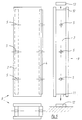
- Fig. 5 shows the plate element 9 bottom left. Fig. 1 to 4 in plan.
- the elevation at the top left in FIG. 5 illustrates the arrangement of the carriers, which have been described above, including the indentations (groove) or protrusions (tongue) (see FIG. 1).
- the side view shows recordings 10, 11 at the top and bottom. These serve to accommodate a basic gauge 12 or a directional gauge 13, the functions of which are described below.
- FIG. 6 shows in plan and side view two of the plate elements 9, which have already been joined together.
- the essential detail in FIGS. 6 and 7 that goes beyond the previous figures is the function of the basic gauge 12.
- the basic teaching function according to the invention is as follows: It will be a problem to set up one plate element after the other in a properly aligned manner and to connect them to one another.
- the basic gauge preferably consists of a longer piece of wood (board or the like) that fits exactly into the receptacle 11 of FIG. 5.
- the basic gauge is precisely aligned and aligned according to the location where the wall is to be placed before the plate elements are set up on the floor and then fastened (screwed, nailed, preferably glued).
- Fig. 5 provided, which also preferably consists of a longer wooden part (board or the like.). This is inserted into the receptacle 10 of FIG. 5 and also connected, preferably glued, to the plate elements in series.
- the leveling gauge also takes on the function of the cover. The ceiling or another component can then be put on.
- FIG. 8 illustrates the principle according to the invention of displacing the individual plate elements.
- the middle plate element is just pushed onto the row of plate elements that has already been created (on the right in FIG. 8).
- the basic gauge 12 and its function described above can be clearly seen in FIG. 8 in elevation (above) and in plan (below).
- a screw jack 16 can be seen, with the help of which you can tighten the screw shown above.
- This screw jack is able to bring a screw hexagon 17 through the bores 5 of the adjacent supports to the screw connection located deep in the plate element in order to tighten.
- 11 and 12 show elevation and plan section of a possible building that has been created with the help of the wooden components according to the invention.
- FIG. 1 The various functions of the wooden components become clear from FIG. They can not only be used as a wall 18 at floor level, but also with appropriate dimensions as a window sill 19 or as a lintel 20. This mention is intended to indicate some possible application variants without even claiming to be complete.
- FIG. 11 Also important are the applications of the wooden components according to the invention shown in FIG. 11 for a floor 21 (cellar ceilings etc.), floor ceilings 22 and also as roof elements 23. Only the dimensions of the wooden components and their members (wooden parts and Intermediate wooden parts according to Fig. 1 ff) and the type of stress.
- FIGS. 13 and 14 The necessary screw connections are indicated by center lines at the relevant points, additional holes 24 having to be made.
- the corner connection is also glued.
- the screw connections of the wooden components to one another are facilitated according to the invention in that the designs shown in FIGS. 15, 16 and 17 are used.
- the problem to be solved is to screw the two adjacent intermediate wooden parts, as shown in FIGS. 6 and 9, in the depth of the plate elements.
- FIG. 16 shows (on the left or in the middle) two versions of the tab 26 according to the invention from FIG. 15. It can be seen that the area X of the tabs has a lower weight than the area Y due to their asymmetrical geometry. The tabs will therefore always reach a stable position with the heavier part pointing downward. When inserted through the holes in the intermediate wooden parts, the heavier part Y initially lies on top, so that position A in FIG. 15 is reached. Due to the above-mentioned rotation by 180 °, the heavier part Y falls down, so that the stable position B in FIG. 15 is established.
- Fig. 16 can also be achieved by other implementations than those indicated here, e.g. by moving an elongated hole 28 in FIG. 16. It is essential that the excess weight is reached after the screw bolt has been turned and thus also the tab by 180 °.
- FIG. 17 Another way to lead a bolt through the above holes of the intermediate wooden parts shows Fig. 17.
- the screw bolt 25 together with a rotatably attached U-part 29 is passed through the holes in the carrier.
- the bolt is then rotated through 180 °, as has already been described for FIGS. 15 and 16.
- the longer and thus heavier part Y of the U-part is overweight and falls down into the stable position B.
- the geometry of the U-part 29 according to the invention leads to the desired problem solution.
- FIG. 17 The right side of the screw connection with the screw bolt 25 and the U-part 29 is shown in FIG. 17, in both positions A and B, which have already been described above. The rotation through 180 ° is also indicated.
- the cross-sectional geometry of the U-part is not limited to the rectangular profile shown. This could also be semicircular or triangular, for example. Rather, what is important is the asymmetrical and rotatable arrangement of the U-part on the screw bolt according to the invention, which leads to tilting due to being overweight in the stable position B after rotation by 180 °. Once the U-Tei has assumed this stable position B, the screw connection can be tightened.
- FIG. 10 already shows the screw jack 16, which is intended to tighten screw connections as described above, by fitting through the holes 5 of adjacent supports, which have already been described in detail, and reaching the relevant screw nuts which are to be tightened. Since it is now necessary to pull back this screw nut and thus the entire screw connection, which has reached its place of use on the way, as described above, so that the tabs acc. Fig. 15 and 16 or the U-part from Fig. 17 on the inside of the intermediate wooden part concerned, the hexagonal area 17 of the screw jack must.
- Fig. 10 can be slightly conical according to the invention, so that the nut 27 of the screw 15 or a corresponding Screw nut of the screw connection acc.
- FIG. 18 shows a further possibility of connecting the two supports of two adjacent plate elements in a force-locking manner.
- This is a screw bolt 30 according to the invention, spanning the distance between the supports in the interior of the plate element and having a screw nut 31 on one side. around which a round steel disc 32 is arranged. All three parts are welded together.
- the steel disc also has two opposite bores 33.
- FIG. 19 A further variant is shown in FIG. 19.
- the screw bolt 30 of FIG. 18 does not extend over the entire length, but is essentially replaced by a tube 34.
- the shortened screw bolt 30 is screwed to a screw nut 35, which in turn is inserted in the tube 34.
- the screw nut 31 and the round steel disk 32 with the two bores 33 are also located on one side. These parts are also all attached to one another by welding.
- FIG. 20 shows the mode of operation of the screw connections according to the invention from FIG. 18 and in particular from FIG. 19.
- Two plate elements 9 are (partly) visible in section.
- the bores 5 in the supports 3 and 4 known from FIGS. 4 ff are clearly recognizable.
- the distance between these supports becomes spanned by the screw connection which has already been described in FIG. 19.
- this protrudes with its threaded bolt 30 into the thread of the screw nut 31 of the adjacent screw connection.
- the screw connection can be tightened by means of a known wrench which fits into the two bores 33 in the steel disk 32 of FIG. 18.
- the bore of the carrier 3 in Fig. 20 must have been slightly enlarged beforehand so that the steel disc 32 fits flush there. The same process preceded the one described above within the wooden component 2, etc.
- This solution also makes the building construction particularly earthquake-proof.
- FIG. 21 the recess already known from FIG. 5 is enlarged by the space 36 in the area of the carrier in question that supply lines 37 and the like can be passed through. These supply lines can even be attached to the base gauge 12 before the plate element is moved. excellent heat and sound cross-section of the wall, ceiling or roof structure.
Abstract
Description
Die Erfindung betrifft ein Montage-Bausystem zum Errichten eines Holzhauses in Modulbauweise, wobei als wesentliche Bauelemente des Bausystems rechteckige Plattenelemente in Kastenbauweise vorgesehen sind.The invention relates to an assembly construction system for erecting a wooden house in a modular construction, wherein rectangular panel elements in a box construction are provided as essential components of the construction system.
Ein derartiges Montage-Bausystem mit den Merkmalen des Oberbegriffs von Patentanspruch 1 ist beschrieben in einem Aufsatz "^Transportable Leicht-Holzhäuser", erschienen in der Zeitschrift "Baumarkt Leipzig", 34. Jahrgang 1935, Seite 1476. Dort werden die miteinander über die Nut-Feder-Verbindung verbundenen Wandteile auf eine durchgehende Schiene aufgesetzt, damit die Wandteile fluchtgerecht ausgerichtet werden können und eine Gesamtstabilisierung eintritt. Die Schiene besteht aus einer unteren Leiste mit rechteckigem Querschnitt, wobei mittig auf die Oberseite der unteren Leiste eine schmalere, kegelstumpfförmig profilierte Leiste aufgesetzt und mit der unteren Leiste verbunden ist. Der untere Aufnahmeraum des Plattenelements hat ein Aufnahmeprofil entsprechend dem Profil der kegelstumpfförmigen schmaleren Leiste, wodurch die gewünschte Richtfunktion erreicht wird.Such a mounting construction system with the features of the preamble of
Diese bekannte Konstruktion hat aber mehrere Nachteile: Zum einen muß eine untere Leiste mit einer kegelstumpfförmigen Aufnahme am Plattenelement als gesondertes Bauteil angebracht werden. Zum anderen muß die Grundleiste mit der kegelstumpfförmigen, schmaleren Leiste versehen werden und diese drei Leisten müssen getrennt angefertigt und mit den betreffenden Teilen verbunden werden. Weiterhin entsteht eine Längsfuge an der fertigen Wand, nämlich zwischen der Oberkante der Grundleiste und der Unterkante des Plattenelements. Derartige Längsfugen sind nachteilig, weil dadurch einmal die Wärmeisolation verschlechtert wird und zum anderen aus ästhetischen Gründen.However, this known construction has several disadvantages: First, a lower bar with a frustoconical receptacle must be attached to the plate element as a separate component. On the other hand, the base strip must be provided with the truncated cone-shaped, narrow strip and these three strips must be made separately and connected to the relevant parts. There is also a longitudinal joint on the finished wall, namely between the upper edge of the base strip and the lower edge of the plate element. Such longitudinal joints are disadvantageous because, on the one hand, this deteriorates the thermal insulation and, on the other hand, for aesthetic reasons.
Weiterhin werden die aneinander anstoßenden Plattenelemente durch in die Nuten eingeschobene Stäbe miteinander verbunden. Auch dieses ist aufwendig.Furthermore, the abutting plate elements are connected to one another by rods inserted into the grooves. This is also complex.
Eine entsprechende Konstruktion ist dort auch an den Oberseiten der Wandelemente vorgesehen und bedingt auch dort die vorstehend erwähnten Nachteile.A corresponding construction is also provided there on the upper sides of the wall elements and also causes the disadvantages mentioned above there.
Die US-A-2 129 441 beschreibt ein ähnliches Montage-Bausystem, bei dem die Plattenelemente über eine Nut-Feder-Verbindung in Modulbauweise miteinander verbunden werden können. Auch an der Oberseite und an der Unterseite der dortigen Plattenelemente springen die massiven Träger gegenüber den Platten um ein bestimmtes Maß zurück, wodurch oben und unten an den Plattenelementen in Längsrichtung durchgehende Aufnahmen geschaffen werden. Diese Aufnahmen dienen zum Verbinden der Plattenelemente mit anderen konstruktiven Elementen des Bausystems.US-A-2 129 441 describes a similar assembly construction system in which the plate elements can be connected to one another via a tongue and groove connection in a modular construction. Also on the top and on the bottom of the plate elements there, the solid supports jump back by a certain amount compared to the plates, whereby continuous recordings are made in the longitudinal direction at the top and bottom of the plate elements. These recordings are used to connect the plate elements with other structural elements of the building system.
Die Nut-Feder-Verbindung wird dort durch ein einfaches Verschieben der Träger aus Massivholz gegenüber den auf die Träger aufgesetzten Platten erreicht, ganz wie bei der vorliegenden Erfindung.The tongue and groove connection is achieved there by simply moving the solid wood supports relative to the plates placed on the supports, just as in the present invention.
Die DE 83 09 825 U1 beschreibt ebenfalls ein Montage-Bausystem mit Plattenelementen in Kastenkonstruktion. Die durchgehenden Träger haben dort ein I-Profil aus Massivholz. Derartige Profile sind in der Herstellung aber sehr aufwendig. Auch fällt bei der Herstellung viel Abfall an.DE 83 09 825 U1 also describes an assembly system with plate elements in a box construction. The continuous beams have an I-section made of solid wood. Such profiles are very expensive to manufacture. There is also a lot of waste during production.
Ein anderes Bausystem, ebenfalls in Holzbauweise ist in der EP 0 072 839 B1 beschrieben. Dort werden die miteinander fluchtend aufgestellten Wandelemente über Stäbe miteinander verbunden, die in entsprechende Aufnahmen (Nuten) an den Seitenkanten der aneinander anstoßenden Plattenelemente eingeschoben werden. Hier sind also zusätzliche Bauelemente zu den kastenförmigen Plattenelementen erforderlich, nämlich die erwähnten Verbindungsstäbe.Another construction system, also in timber construction, is described in EP 0 072 839 B1. There, the wall elements set up in alignment with one another are connected to one another via rods which are inserted into corresponding receptacles (grooves) on the side edges of the abutting plate elements. So here additional components to the box-shaped plate elements are required, namely the connecting rods mentioned.
Die WO 88/03978 beschreibt ein anderes Bausystem, bei der die Plattenelemente über zusätzliche Riegel miteinander verbunden werden, die in Schlitze eingeschoben werden, die in Querrichtung der Plattenelemente angelegt sind. Die Riegel verletzen somit die Außenhaut der Plattenelemente. Sie dienen als Widerlager zum Verschrauben der aneinander anstoßenden Plattenelemente. Hier ist es außerdem schwierig, die Muttern der Verschraubungen anzuziehen, weil sie nicht frei zugänglich sind und für dieses Problem wird dort keine brauchbare Lösung vorgeschlagen.WO 88/03978 describes another construction system in which the plate elements are connected to one another via additional bars which are inserted into slots which are created in the transverse direction of the plate elements. The bars thus damage the outer skin of the plate elements. They serve as an abutment for screwing the abutting plate elements. Here it is also difficult to tighten the nuts of the screw connections because they are not freely accessible and no useful solution to this problem is proposed there.
Die EP 0 197 958 B1 beschreibt ein Bausystem, bei dem in den durchgehenden Trägern miteinander fluchtende Bohrungen angelegt sind, durch die Versorgungsleitungen hindurchgesteckt werden können. Für jede Versorgungsleitung muß dort somit ein miteinander fluchtendes System von der Bohrungen vorgesehen sein, was aufwendig ist. Noch stärker fällt nachteilig ins Gewicht, daß die Versorgungsleitungen in die Bohrungen gewissermaßen eingefädelt werden müssen, was an Ort und Stelle schwierig zu bewerkstelligen ist. Dieses Einfädeln muß erfolgen, bevor die Beplankung der Plattenelemente angebracht wird. Die erforderliche Wärmedämmung ist an diesen Stellen überhaupt nicht mehr einzubringen.EP 0 197 958 B1 describes a construction system in which bores which are aligned with one another are made in the continuous supports and through which supply lines can be inserted. For each supply line there must therefore be an aligned system of the holes, which is expensive. Even more disadvantageous is the fact that the supply lines have to be threaded into the holes, as it were, which is difficult to accomplish on the spot. This threading must be done before the paneling of the panel elements is attached. The required thermal insulation can no longer be introduced at these points.
Die DE-AS 1 219 653 beschreibt ein anderes Holzmontage-Bausystem, wobei die aneinander anstoßenden Plattenelemente über Bolzen miteinander verbunden werden, deren Köpfe länglich gestreckt sind. Man muß also zum Hindurchstecken der Bolzen mit ihren länglichen Köpfen in den Plattenelementen entsprechende Schlitze anbringen . Anschließend werden die Bolzen um 90° gedreht, so daß sie durch die Schlitze nicht mehr herausrutschen können und schließlich festgeschraubt. Derartig längliche Schlitze sind aber schwieriger herzustellen als Löcher mit kreisrundem Querschnitt, die durch einfaches Bohren angelegt werden können.DE-AS 1 219 653 describes another wood assembly construction system, the abutting plate elements being connected to one another by means of bolts, the heads of which are elongated. So you have to make appropriate slots in the plate elements to insert the bolts with their elongated heads. Then the bolts are turned 90 ° so that they can no longer slide out through the slots and finally screwed tight. Such elongated slots are more difficult to make than holes with a circular cross-section, which can be created by simply drilling.
Die Erfindung vermeidet die erwähnten Nachteile. Ihr liegt die Aufgabe zugrunde, ein Montage-Bausystem mit den Merkmalen des Oberbegriffs von Patentanspruch 1 vorzuschlagen, das sich insbesondere durch eine einfache Herstellung und Montage auszeichnet und bei dem insbesondere die Versorgungsleitungen in der jeweils gewünschten Anzahl und Anordnung auf einfache Art und Weise verlegt werden können, ohne daß darunter die ggf. vorgesehene Wärmedämmung des Gebäudes fühlbar leidet.The invention avoids the disadvantages mentioned. You are the Object of the task to propose an assembly system with the features of the preamble of
Zur Lösung dieser Aufgabe dienen die kennzeichnenden Merkmale von Patentanspruch 1.The characteristic features of
Weil die Richtbohlen rechteckige Querschnitte haben, sind sie sehr einfach zu fertigen. Weil sie (von oben und/oder von unten) in die entsprechenden Aufnahmen der Plattenelemente eingesetzt werden, gibt es keine störenden Fugen oben und unten an den Plattenelementen, wie beim gattungsbildenden Stand der Technik. Die hier ohnedies vorhandenen Aufnahmen an der Oberseite und Unterseite der Plattenelemente werden erfindungsgemäß größer gemacht als dies für die Richtbohlen an und für sich nötig wäre und der zusätzliche Platz wird zur Aufnahme der Versorgungsleitungen genutzt.Because the straightening planks have rectangular cross sections, they are very easy to manufacture. Because they are inserted (from above and / or from below) into the corresponding receptacles of the plate elements, there are no disruptive joints at the top and bottom of the plate elements, as in the generic state of the art. According to the invention, the recordings on the top and bottom of the plate elements, which are present anyway, are made larger than would be necessary for the leveling planks per se and the additional space is used to accommodate the supply lines.
Die Plattenelemente können an beliebigen Stellen des zu errichtenden Gebäudes eingesetzt werden, wie dies im speziellen Beschreibungsteil noch näher erläutert wird, beispielsweise als Wandelemente, Deckenelemente und/oder Dachelemente. Wenn sie als Wandelemente verwendet werden, d.h. bei lotrechter Anordnung, muß dafür gesorgt werden, daß die obere Richtbohle den erwähnten Freiraum für die dortigen Versorgungsleitungen freiläßt, wenn auch oben Versorgungsleitungen verlegt werden sollen. Aus diesem Grunde werden die in Patentanspruch 2 angegebenen Auflager für die obere Richtbohle bevorzugt, die an den ohnedies vorhandenen Trägern ausgebildet sind.The plate elements can be used at any point in the building to be erected, as will be explained in more detail in the special description part, for example as wall elements, ceiling elements and / or roof elements. When used as wall elements, i.e. with vertical arrangement, care must be taken to ensure that the upper leveling screed leaves the aforementioned space for the supply lines there, even if supply lines are to be laid above. For this reason, the supports specified in
Die Träger sollen aus Massivholz bestehen und bezüglich der an den Trägern anliegenden Platten wird es ebenfalls bevorzugt, wenn diese aus Holz oder Holzwerkstoff bestehen. Sie können auch aus organisch gebundenen Platten oder aus Platten mit mineralischer Bindung bestehen. Organisch gebundene Platten sind leimgebundene Holzplatten. Anorganisch bzw. mineralisch gebundene Platten sind beispielsweise gipsgebundene Platten, nicht aber zementgebundene Platten.The beams should consist of solid wood, and with regard to the plates that rest against the beams, it is also preferred if they consist of wood or wood-based material. You can also consist of organically bound plates or plates with a mineral bond. Organically bound boards are glued wood boards. Inorganically or mineral-bound boards are, for example, gypsum-bound boards, but not cement-bound boards.
Bezüglich der Verbindung der Bauelemente jedes Plattenelements miteinander und auch der Plattenelemente miteinander wird es bevorzugt, wenn diese durch eine vollflächige Verleimung erfolgt, weil auch dies, zusammen mit der grundlegenden Holzkonstruktion, heutigen Anforderungen an die Holzbauweise sehr gut entspricht. Zusätzlich können die Bauteile miteinander verschraubt oder vernagelt werden, wobei dies in erster Linie dazu dient, die Teile aneinander gepreßt zu halten, bis der Leim abgebunden ist.With regard to the connection of the components of each panel element to one another and also of the panel elements to one another, it is preferred if this is done by gluing over the entire surface, because this, together with the basic timber construction, corresponds very well to today's requirements for timber construction. In addition, the components can be screwed or nailed to one another, this primarily serving to hold the parts pressed together until the glue has set.
Für das erwähnte Verschrauben der Teile miteinander sind bevorzugte Ausführungsformen in den Patentansprüchen 4 bis 10 angegeben.For the mentioned screwing of the parts together, preferred embodiments are given in
Das erfindungsgemäße Bausystem zeichnet sich unter anderem somit dadurch aus, daß die im Rahmen der Nut-Feder-Verbindung aneinanderstoßenden durchgehenden Träger zusammen einen verstärkten Balken ausbilden, wodurch eine erhöhte Stabilität erzielt wird. Es entsteht ein Paket mit neuen statischen Eigenschaften.The construction system according to the invention is thus characterized, inter alia, in that the continuous beams which abut one another in the context of the tongue and groove connection together form a reinforced beam, as a result of which increased stability is achieved. A package with new static properties is created.
Zum Ausrichten der Wandlemente dienen die oben und unten vorgesehenen Richtbohlen. Diese erstrecken sich über die ganze zu erstellende Wand, also über mehrere Breiten der Plattenelemente (Wandteile). Sie werden am Boden befestigt und verleimt bzw. oben in den dazu vorgesehenen Öffnungen eingelegt, die sich allein durch die Ausbildung und Anordnung der einzelnen Bauteile (Träger und Platten) der Plattenelement bilden. Es sind also keine zusätzlichen Konstruktionsteile erforderlich; vielmehr müssen lediglich die Träger kürzer ausgebildet werden als die Platten.The leveling planks provided above and below are used to align the wall elements. These extend across the entire wall to be created, i.e. across several widths of the panel elements (wall parts). They are attached to the floor and glued or inserted into the openings provided for this purpose, which are formed solely by the design and arrangement of the individual components (supports and plates) of the plate element. So no additional construction parts are required; rather, only the supports have to be made shorter than the plates.
Die Stabilisierung der Plattenelemente zueinander wird erfindungsgemäß durch drei sich ergänzende konstruktive Maßnahmen erreicht, nämlich durch die Nut-Feder-Ausbildung der Seiten der Wandteile bzw. Plattenelemente, durch die untere Richtbohle und durch die obere Richtbohle. Hinzu kommt die Verleimung der Teile miteinander.The stabilization of the plate elements relative to one another is achieved according to the invention by three complementary constructive measures, namely by the tongue and groove design of the sides of the wall parts or plate elements, by the lower leveling board and by the top leveling board. In addition, the parts are glued together.
Die obere Richtbohle oder Richtlehre übt drei Funktionen aus, nämlich das Schließen der Plattenelemente an der Oberseite, ein fluchtgerechtes Ausrichten der Teile untereinander und eine Stabilisierung oder Aussteifung des Gesamtsystems. Entsprechendes gilt für die untere Richtbohle, auch Grundlehre genannt.The upper leveling screed or leveling gauge performs three functions, namely closing the plate elements on the top, aligning the parts with one another in line with one another, and stabilizing or stiffening the overall system. The same applies to the lower directional screed, also called basic gauge.
Erfindungsgemäß können ganze Bündel von Versorgungsleitungen in den entsprechenden Freiräumen verlegt werden, und zwar in der jeweils gewünschten Anordnung. Sie können fast den ganzen Querschnitt des Plattenelements einnehmen, ggf. an beiden Seiten oder auch nur an einer Seite des Plattenelements. Der gesamte Raum zwischen den Versorgungsleitungen bleibt frei für zusätzliche Wärmedämmung, insbesondere Schüttmaterial. Die Verlegung der Versorgungsleitungen ist schon vor dem Versetzen der Plattenelemente möglich (im unteren Bereich auf der Grundlehre), aber auch wenn die Plattenelemente schon fertig versetzt sind (oberer Bereich unterhalb der Richtlehre). Weiterhin wird der Querschnitt durch die erwähnten Freiräume nur unwesentlich geschwächt.According to the invention, entire bundles of supply lines can be laid in the corresponding free spaces, in the desired arrangement. You can take up almost the entire cross-section of the plate element, if necessary on both sides or only on one side of the plate element. The entire space between the supply lines remains free for additional thermal insulation, in particular bulk material. It is possible to lay the supply lines before moving the plate elements (in the lower area on the basic gauge), but also when the plate elements have already been moved (upper area below the leveling gauge). Furthermore, the cross-section is only marginally weakened by the free spaces mentioned.
Die in den Patentansprüchen 7 bis 10 angesprochenen Verschraubungen haben die Eigenheit, daß sie nach einem Drehen des betreffenden Bolzens ihren Querschnitt vergrößern und dadurch ein Zurückrutschen des Bolzens sicher verhindern. Trotzdem sind zum Durchstecken des Bolzens mitsamt dem Sicherungselement nur kreisrunde Bohrungen notwendig, die leicht angelegt werden können. Trotz der häufig schwierigen Zugänglichkeit der Verschraubungen können diese bei der erfindungsgemäßen Konstruktion angezogen bzw. wieder gelöst werden.The screw connections mentioned in patent claims 7 to 10 have the peculiarity that they enlarge their cross-section after turning the relevant bolt and thereby reliably prevent the bolt from slipping back. In spite of this, only circular holes, which can be easily created, are necessary for pushing through the bolt together with the securing element. Despite the often difficult accessibility of the screw connections, they can be tightened or loosened again in the construction according to the invention.
Die Erfindung wird im folgenden anhand von Ausführungsbeispielen näher erläutert, aus denen sich weitere wichtige Merkmale ergeben. Es zeigt:
- Fig. 1
- eine Draufsicht auf ein erfindungsgemäßen Plattenelement in einer ersten Ausführungsform;
- Fig. 2
- eine Draufsicht auf ein demgegenüber abgewandeltes Plattenelement;
- Fig. 3
- eine Draufsicht auf ein gegenüber Fig. 1 abgewandeltes Plattenelement;
Fi.g 4- eine Draufsicht auf ein gegenüber Fig. 2 abgewandeltes Plattenelement;
- Fig. 5
- in drei Ansichten eine Draufsicht entsprechend Fig. 1, eine Ansicht des Plattenelements von Fig. 1 und eine Stirnansicht dieses Plattenelements, wobei beabstandet dazu zwei Richtbohlen gezeigt sind;
- Fig. 6
- eine Ansicht bzw. eine Draufsicht zweier miteinander verbundener Plattenelemente, hier als Wandelemente;
- Fig. 7
- einen Schnitt längs der Linie A-A von Fig. 6;
- Fig. 8
- eine Ansicht bzw. Draufsicht auf mehrere der Wandelemente bei deren Montage;
- Fig. 9
- ein vergrößerter Schnitt durch die Enden zweier aneinander anstoßender Plattenelemente mit Verschraubung der Träger der Plattenelemente;
- Fig. 10
- eine Schraubwinde zum Betätigen der Verschraubung;
- Fig. 11
- schematisch eine Ansicht eines mit dem erfindungsgemäßen Bausystem errichteten Holzhauses;
- Fig. 12
- einen Schnitt längs der Linie A-A von Fig. 11;
- Fig. 13
- in demgegenüber vergrößertem Maßstab eine Ansicht einer Ecke dieses Gebäudes;
- Fig. 14
- eine Draufsicht auf Fig. 13;
- Fig. 15
- eine Ansicht der wesentlichen Teile einer Ausführungsform der Schraubverbindung;
- Fig. 16
- die dabei verwendete Lasche in drei Ansichten;
- Fig. 17
- ein U-Teil als Arretierung der Schraubverbindung in einer Seitenansicht bzw. in einer Stirnansicht, und zwar zusammen mit dem zugehörigen Bolzen;
- Fig. 18
- eine Seitenansicht bzw. Stirnansicht einer weiteren Ausführungsform einer erfindungsgemäßen Schraubverbindung;
- Fig. 19
- eine Ansicht einer demgegenüber abgewandelten Schraubverbindung;
- Fig. 20
- die Verwendung der Schraubverbindung nach Fig. 19 zum Verbinden zweier Plattenelemente miteinander;
- Fig. 21
- eine Stirnansicht des unteren Teils eines Plattenelements (Wandelement) mit zusätzlichen Versorgungsleitungen;
- Fig. 22
- eine Stirnansicht entsprechend Fig. 21, wobei der obere Teil des Wandelements mitsamt den dort verlegten Versorgungsleitungen gezeigt ist.
- Fig. 1
- a plan view of a plate element according to the invention in a first embodiment;
- Fig. 2
- a plan view of a modified plate element;
- Fig. 3
- a plan view of a modified plate element compared to Figure 1;
-
Fi.g 4 - a plan view of a modified plate element compared to FIG. 2;
- Fig. 5
- in three views a plan view corresponding to FIG. 1, a view of the plate element from FIG. 1 and an end view of this plate element, two directional screeds being shown at a distance therefrom;
- Fig. 6
- a view or a plan view of two interconnected plate elements, here as wall elements;
- Fig. 7
- a section along the line AA of Fig. 6;
- Fig. 8
- a view or plan view of several of the wall elements during their assembly;
- Fig. 9
- an enlarged section through the ends of two abutting plate elements with screwing the carrier of the plate elements;
- Fig. 10
- a screw jack for actuating the screw connection;
- Fig. 11
- schematically a view of a wooden house erected with the construction system according to the invention;
- Fig. 12
- a section along the line AA of Fig. 11;
- Fig. 13
- in contrast, an enlarged view of a corner of this building;
- Fig. 14
- a plan view of Fig. 13;
- Fig. 15
- a view of the essential parts of an embodiment of the screw connection;
- Fig. 16
- the tab used in three views;
- Fig. 17
- a U-part as locking of the screw connection in a side view or in a front view, together with the associated bolt;
- Fig. 18
- a side view or front view of a further embodiment of a screw connection according to the invention;
- Fig. 19
- a view of a modified screw connection;
- Fig. 20
- the use of the screw connection according to FIG. 19 for connecting two plate elements to one another;
- Fig. 21
- an end view of the lower part of a plate element (wall element) with additional supply lines;
- Fig. 22
- an end view corresponding to FIG. 21, wherein the upper part of the wall element is shown together with the supply lines laid there.
Das erfindungsgemäße Holz-Bauelement wird in Fig. 1 in der Aufsicht (Grundriß) gezeigt. Es besteht aus den beiden raumschließenden Platten 1 und 2 aus Holz oder Holzwerkstoff mit organischer oder anorgansischer (mineralischer) Bindung. Diese sind miteinander durch Träger 3 und aus Massivholz verbunden. Die Platten 1 und 2 sind mit den Trägern 3 und 4 verleimt und/oder verschraubt. Die Verleimung hat den Vorteil der besseren Kräfteverteilung, so daß dieser vollflächigen Verbindungsart der Vorzug gebührt. Die Verschraubung kann ggf. der ersten Befestigung dienen, bis der Leim ausghärtet und abgebunden ist.The wood component according to the invention is shown in plan view in Fig. 1 (plan view). It consists of the two room-
Dieses Plattenelement 9, bestehend aus den miteinander verleimten Platten 1 und 2 sowie den Trägern 3 und 4, stellt den Grundbaustein (Modul) des erfindungsgemäßen Holz-Bausystems dar.This
Man erkennt in Fig. 1, daß die beiden Träger 3 und 4 ungleich (unsymmetrisch) angebracht sind. Die Ursache ist darin zu sehen, daß durch das Versetzen des Trägers 3 eine Nut 6 entsteht, in welche genau der überstehende Bereich 7 (Feder) des Trägers 5 eines benachbarten, identischen Plattenelements hineinpaßt. Hierdurch entsteht eine kraftschlüssige Verbindung zwischen den zwei Plattenelementen.It can be seen in Fig. 1 that the two
Die Feder 7 des Plattenelements kann angepaßt werden, damit sie besser in die Nut 6 des benachbarten Plattenelements hineingeschoben werden kann.The
Des weiteren sind in Fig. 1 Bohrungen 5 erkennbart, auf die weiter unten eingegangen wird.Furthermore, holes 5 can be seen in FIG. 1, which will be discussed further below.
Fig. 2 zeigt dasselbe Schema wie Fig. 1, jedoch mit dem Unterschied, daß die Platten 1 und 2 von Fig. 1 jeweils aus zwei Teilplatten 1a und 1b bzw. 2a und 2b bestehten. Diese Teilung der beiden Platten könnte zum Beispiel durch vorgegebene Abmessungen der gewählten Holzteile (Bretter) notwendig werden. Für diesen Fall wird ein weiterer Träger 8 notwendig, der zusätzlich zu den beiden Trägern 3 und 4 eingefügt wird.Fig. 2 shows the same scheme as Fig. 1, but with the difference that the
Der Träger 8 ist mit den Teilplatten 1a und 1b sowie 2a und 2b verschraubt und/oder verteilhaft verleimt, wie dies zuvor für die Platten beschrieben ist. Dasselbe gilt für weitere Teilungen.The
Der zusätzliche Träger 8 hat ebenfalls eine Bohrung 5 in gleicher Flucht mit den Bohrungen 5 der beiden anderen Träger 3 und 4.The
In den Fig. 1 und 2 sind die Verschraubungen lediglich durch Mittellinien angedeutet.1 and 2, the screw connections are only indicated by center lines.
Fig. 3 und 4 zeigen Grundrisse von erfindungsgemäßen Holz-Plattenelementen mit denselben Funktionen, wie sie bereits für Fig. 1 und 2 beschrieben worden sind, jedoch mit dem Unterschied, daß die jeweiligen Träger in die Platten eingelassen und dort verleimt worden sind. Diese Bauart gem. Fig. 3 und 4 kann vorteilhaft bei maschineller Fertigung gewählt werden.3 and 4 show floor plans of wood-panel elements according to the invention with the same functions as they already do 1 and 2 have been described, but with the difference that the respective carriers have been inserted into the plates and glued there. This type acc. 3 and 4 can advantageously be selected in the case of mechanical production.
Fig. 5 zeigt links unten das Plattenelement 9 gem. Fig. 1 bis 4 im Grundriß.Fig. 5 shows the
Der Aufriß links oben in Fig. 5 veranschaulicht die Anordnung der Träger, welche zuvor einschließlich der Einrückungen (Nut) bzw. Überstände (Feder) beschrieben worden sind (s. Fig. 1).The elevation at the top left in FIG. 5 illustrates the arrangement of the carriers, which have been described above, including the indentations (groove) or protrusions (tongue) (see FIG. 1).
Im Seitenriß rechts in Fig. 5 sind wiederum die erwähnten Bohrungen 5 aus Fig. 1 erkennbar, sowie ein Träger 5.In the side view on the right in FIG. 5, the
Der Seitenriß zeigt oben und unten Aufnahmen 10, 11. Diese dienen der Aufnahme einer Grundlehre 12 bzw. einer Richtlehre 13, deren Funktionen nachfolgend beschrieben wird.The side view shows
Fig. 6 zeigt im Grundriß und Seitenriß zwei der Plattenelemente 9, die bereits aneinandergefügt worden sind. Das wesentliche, über die bisherigen Figuren hinausgehende Detail in Fig. 6 und 7 ist die Funktion der Grundlehre 12.Fig. 6 shows in plan and side view two of the
Die erfindungsgemäße Funktion der Grundlehre ist folgende:
Es wird ein Problem darstellen, ein Plattenelement nach dem anderen sauber ausgefluchtet aufzustellen und miteinander zu verbinden. Die Grundlehre besteht vorzugsweise aus einem längeren Holzteil (Brett oder dergl.), das genau in die Aufnahme 11 von Fig. 5 paßt. Die Grundlehre wird vor dem Aufstellen der Plattenelemente auf dem Boden genau ausgerichtet und ausgefluchtet entsprechend der Stelle, wo die Wand erstellt werden soll, und anschließend befestigt (geschraubt, genagelt, vorzugsweise verleimt).The basic teaching function according to the invention is as follows:
It will be a problem to set up one plate element after the other in a properly aligned manner and to connect them to one another. The basic gauge preferably consists of a longer piece of wood (board or the like) that fits exactly into the
Es dürfte sich empfehlen, den gesamten Fußboden zunächst einmal mit den Grundlehren zu versehen. Der Grundriß ist dann schon genau erkennbar.It should be advisable to start with the entire floor to be provided with the basic tenets. The floor plan is already clearly recognizable.
Erst jetzt werden die Plattenelemente 9 Stück für Stück so auf die Grundlehre aufgesetzt und verleimt, wie dies aus Fig. 6 und 7 ersichtlich ist. Die Plattenelemente stehen dann an der richtigen Stelle und sind schon ausgefluchtet.Only now are the
Sind die Plattenelemente in der genannten Weise erstellt, werden sie mit der Richtlehre 13 gem. Fig. 5 versehen, welche ebenfalls vorzugsweise aus einem längeren Holzteil (Brett oder dergl.) besteht. Dieses wird in die Aufnahme 10 von Fig. 5 eingesetzt und ebenfalls mit den in Reihe stehenden Plattenelementen verbunden, vorzugsweise verleimt.Are the plate elements created in the manner mentioned, they are with the
Neben der genauen Ausrichtung der Plattenelemente übernimmt die Richtlehre auch noch die Funktion der Abdeckung. Es kann sodann die Decke oder ein anderes Bauteil aufgelegt werden.In addition to the precise alignment of the plate elements, the leveling gauge also takes on the function of the cover. The ceiling or another component can then be put on.
Fig.8 verdeutlicht das erfindungsgemäße Prinzip des Versetzens der einzelnen Plattenelemente. Das mittlere Plattenelement wird gerade an die schon ertellte Reihe der Plattenelemente (rechts in Fig. 8) angeschoben. Deutlich ist in Fig. 8 im Aufriß (oben) und im Grundriß (unten) die Grundlehre 12 und deren oben beschriebene Funktion zu erkennen.8 illustrates the principle according to the invention of displacing the individual plate elements. The middle plate element is just pushed onto the row of plate elements that has already been created (on the right in FIG. 8). The
Im Grundriß (unten) von Fig. 8 erkennt man ebenfalls deutlich die formschlüssige Verbindung der Plattenelemente 9 untereinander (Nut und Feder), die in Fig. 1 bereits vorbereitend beschrieben wurde und die auch besonders in Fig. 6 klar ersichtlich ist.8 also clearly shows the positive connection of the
Zusätzlich zur formschlüssigen Verbindung der Plattenelemente untereinander kommt noch die kraftschlüssige Verbindung durch Verschrauben und Verleimen. Fig. 9 zeigt eine mögliche Verbindung durch Verschrauben. An dieser Stelle wird auch deutlich, wozu die schon früher mehrfach erwähnten Bohrungen 5, die fluchtend angeordnet sein müssen, dienen (s. besonders Fig. 1 und 5), Mit Hilfe dieser Verschraubung 14 nebst Unterlagscheibe 15 werden die in Fig. 1 ff näher beschriebenen Träger 3 und 4 miteinander verbunden.In addition to the positive connection of the plate elements to each other, there is also the positive connection by screwing and gluing. Fig. 9 shows a possible connection by screwing. At this point it is also clear what the
In Fig. 10 ist eine Schraubwinde 16 zu sehen, mit deren Hilfe man die oben dargestellte Verschraubung festziehen kann. Man ist mit dieser Schraubwinde in der Lage, einen Schraubsechskant 17 durch die Bohrungen 5 der benachbarten Träger hindurch an die tief in dem Plattenelement liegende Verschraubung heranzuführen, um sich festzuziehen.In Fig. 10, a
Fig. 11 und 12 zeigen Aufriß und Grundrißschnitt eines möglichen Gebäudes, das mit Hilfe der erfindungsgemäßen Holz-Bauelemente erstellt worden ist.11 and 12 show elevation and plan section of a possible building that has been created with the help of the wooden components according to the invention.
Aus Fig. 11 werden die verschiedenen Funktionen der Holz-Bauelemente deutlich. Sie können nicht nur als Wand 18 in Geschoßhöhe raumschließend verwendet werden, sondern auch bei entsprechender Dimensionierung als Fensterbrüstung 19 oder als Fenstersturz 20. Diese Erwähnung soll auf einige mögliche Anwendungsvarianten hinweisen ohne auch nur annähernden Anspruch auf Vollständigkeit.The various functions of the wooden components become clear from FIG. They can not only be used as a
Wichtig sind auch die aus Fig. 11 ersichtlichen Anwendungen der erfindungsgemäßen Holz-Bauelemente für einen Fußboden 21 (Kellerdecken usw.), Geschoßdecken 22 und auch als Dachelemente 23. Es ändern sich dabei lediglich die Abmessungen der Holz-Bauelemente und deren Glieder (Holzteile und Zwischen-Holzteile gem. Fig. 1 ff) und die Art der Beanspruchung.Also important are the applications of the wooden components according to the invention shown in FIG. 11 for a floor 21 (cellar ceilings etc.),
Wenn diese Beanspruchungen bei Wänden vor allem Druck- und Knickbelastungen sind, so liegen bei Decken und Dächern vor allem Biege- und Querkräfte vor. Immer aber leistet das erfindungsgemäße Holz-Bauelement alle Anforderungen, und zwar durch das Zusammenwirken aller Glieder gem. Fig. 1 ff im Zug- und Druckbereich, und zusätzlich durch die erfindungsgemäßpen form- und kraftschlüssigen Verbindungen der Holz--Bauelemente untereinander.If these loads on walls are primarily pressure and buckling loads, then there are primarily bending and shear forces on ceilings and roofs. But always the wood component according to the invention meets all requirements, namely by the interaction of all links acc. Fig. 1 ff in the tension and compression area, and additionally by the inventivepen positive and non-positive connections between the wood components.
Aus Fig. 12 soll hervorgehen, daß auch Eckverbindungen kein Problem darstellen. Die Detail-Lösung hierzu ist aus Fig. 13 und 14 ersichtlich. Die notwendigen Verschraubungen sind durch Mittlinien an den betreffenden Stellen angedeutet, wobei zusätzliche Bohrungen 24 angebracht werden müssen. Auch die Eckverbindung ist verleimt.From Fig. 12 it should be apparent that corner connections are also not a problem. The detailed solution for this is shown in FIGS. 13 and 14. The necessary screw connections are indicated by center lines at the relevant points,
Die Verschraubungen der Holz-Bauelemente untereinander werden erfindungsgemäß dadurch erleichtert, daß die in Fig. 15, 16 und 17 gezeigten Ausführungen zur Anwendung kommen. Es ist das Problem zu lösen, eine Verschraubung der beiden benachbarten Zwischen-Holzteile, wie aus Fig. 6 und 9 ersichtlich, in der Tiefe der Plattenelemente vorzunehmen.The screw connections of the wooden components to one another are facilitated according to the invention in that the designs shown in FIGS. 15, 16 and 17 are used. The problem to be solved is to screw the two adjacent intermediate wooden parts, as shown in FIGS. 6 and 9, in the depth of the plate elements.
Hierzu bedient man sich der Schraubbolzen 25 gem. Fig. 15, die mit den erfindungsgemäßen Laschen 26 ausgerüstet sind.For this purpose, use the
In der Stellung A (Fig. 15) dieser beiden Laschen wird der Schraubbolzen 25 zusammen mit der Schraubmutter 27 durch die kreisrunde Bohrung 5 der Träger 3, 4, 8 hindurchgeführt. Dies ist möglich, weil die Laschen 26 in der Stellung A eng am Bolzen 25 anliegen.In position A (FIG. 15) of these two tabs, the
Wenn der Schraubbolzen 25 mit den Laschen 26 sowie der Schraubmutter 27 den Bereich der beiden zu verschraubenden Träger erreicht hat, wobei sich diese zwischen den beiden Laschen 26 befinden, dann wird der Schraubbolzen 25 um 180° gedreht. Dadurch drehen sich die beiden Laschen infolge des Übergewichts aufgrund ihrer Unsymmetrie um und erreichen die Lage B in Fig. 15. Jetzt ist die geometrische Ausdehnung der beiden Laschen 2 und 3 größer als die Bohrung, durch die sie hindurchgeführt worden sind, und der Schraubbolzen kann mittels der Schraubmutter 27 angezogen werden. (Die beiden zu verbindenden Träger sind wegen der besseren Übersichtlichkeit der Zeichnung weggelassen worden.)When the
In Fig. 16 sind (links bzw. in der Mitte) zwei Ausführungen der erfindungsgemäßen Lasche 26 aus Fig. 15 dargestellt. Man sieht, daß der Bereich X der Laschen aufgrund deren unsymmetrischer Geometrie ein geringeres Gewicht aufweist als der Bereich Y. Die Laschen werden somit immer eine stabile Lage dahingehend erreichen, daß der schwerere Teil nach unten weist. Beim Einschieben durch die Bohrungen der Zwischen-Holzteile liegt der schwerere Teil Y zunächst oben, so daß die Lage A in Fig. 15 erreicht wird. Aufgrund der oben erwähnten Drehung um 180° fällt der schwerere Teil Y nach unten, so daß sich die stabile Lage B in Fig. 15 einstellt.16 shows (on the left or in the middle) two versions of the
Die erfindungsgemäße unsymmetrische Geometrie der Laschen gem. Fig. 16 kann auch durch andere Ausführungen erreicht werden, als sie hier angezeigt werden, z.B. durch Verschieben eines Langlochs 28 in Fig. 16. Wesentlich ist das Erreichen des Übergewichts nach Drehen des Schraubbolzens und somit auch der Lasche um 180°.The asymmetrical geometry of the tabs according to the invention. Fig. 16 can also be achieved by other implementations than those indicated here, e.g. by moving an
Beim Anziehen des Schraubbolzens 25 in Fig. 15 mittels der Schraubmutter 27 verkrallen sich die Laschen 26 aufgrund der angespritzten erfindungsgemäßen Ausführungen von Fig. 16 zusätzlich in das Holz der Träger, so daß eine erneute, ungewollte Drehung der Laschen während des Anziehens der Schraubmutter in Fig. 15 vermieden wird. Diese angespitzte Ausführung führt erstens zu dem gewünschten Verkrallen der Lasche im Holz, andererseits aber führt sie zu der erforderlichen erfindungsgemäßen unsymmetrischen Geometrie der Laschen mit den oben beschriebenen Wirkungen.When the
Eine kraftschlüssige Verbindung zweier zu verbindender Holt-Bauelemente ist mit der gezeigten Konstruktion gewährleistet.A non-positive connection between two Holt components to be connected is guaranteed with the construction shown.
Eine weitere Möglichkeit, einen Schraubbolzen durch die oben genannten Bohrungen der Zwischen-Holzteile zu führen, zeigt Fig. 17. In der Stellung A der erfindungsgemäßen Verschraubung wird der Schraubbolzen 25 zusammen mit einem drehbar angebrachten U-Teil 29 durch die Bohrungen der Träger hindurchgeführt. Sodann wird der Bolzen um 180° gedreht, wie dies schon für Fig. 15 und 16 beschrieben worden ist. Hierdurch erhält das längere und somit schwerere Teil Y des U-Teils das Übergewicht und fällt nach unten in die stabile Lage B. Auch hier wieder führt die erfindungsgemäße Geometrie des U-Teils 29 zur gewünschten Problemlösung.Another way to lead a bolt through the above holes of the intermediate wooden parts shows Fig. 17. In position A of the screw connection according to the invention, the
In Fig. 17 rechts ist die Stirnseite der Verschraubung mit dem Schraubbolzen 25 und dem U-Teil 29 gezeigt, und zwar in beiden Lagen A und B, die oben bereits beschrieben worden sind. Die Drehung um 180° ist ebenfalls angedeutet.The right side of the screw connection with the
Die Querschnittsgeometrie des U-Teils ist nicht auf das gezeigte rechteckige Profil beschränkt. Dieses könnte beispielsweise auch halbrund oder dreieckig sein. Wichtig ist vielmehr die erfindungsgemäße unsymmetrische und drehbare Anordnung des U-Teils auf dem Schraubbolzen, die zum Kippen durch Übergewicht in die stabile Lage B führt nach Drehung um 180°. Hat das U-Tei diese stabile Lage B eingenommen, so kann die Verschraubung festgezogen werden.The cross-sectional geometry of the U-part is not limited to the rectangular profile shown. This could also be semicircular or triangular, for example. Rather, what is important is the asymmetrical and rotatable arrangement of the U-part on the screw bolt according to the invention, which leads to tilting due to being overweight in the stable position B after rotation by 180 °. Once the U-Tei has assumed this stable position B, the screw connection can be tightened.
Fig. 10 zeigte bereits die Schraubwinde 16, die dazu bestimmt ist, Verschraubungen wie oben beschrieben festzuziehen, indem sie durch die früher schon eingehend beschriebenen Bohrungen 5 benachbarter Träger hindurchpaßt und an die betreffenden Schraubmuttern, die festgezogen werden sollen, gelangt. Da es nun erforderlich ist, diese Schraubmutter und somit die ganze Verschraubung, die auf dem Wege an ihren Einsatzort, wie oben beschrieben, gelangt ist, ein wenig wieder zurückzuziehen, damit sich die Laschen gem. Fig. 15 und 16 oder das U-Teil aus Fig. 17 an die Innenseite des betreffenden Zwischen-Holzteils anlegen, muß der Sechskantbereich 17 der Schraubwinde gem. Fig. 10 erfindungsgemäß leicht konisch ausgeführt sein, damit sich die Schraubmutter 27 der Verschraubung 15 oder eine entsprechende Schraubmutter der verschraubung gem. Fig. 17 dort leicht verkantet bzw. festklemmt und somit nicht aus dem Sechskantbereich 1 von Fig. 10 herausfällt, wenn man die genannten Verschraubungen mittels der Schraubwinde aus Fig. 10 für ein kurzes Stück wieder zurückzieht. Sodann kann die Verschraubung problemlos angezogen werden, wobei sich die Schraubmutter 27 gem. Fig. 15 leicht wieder aus dem Sechskantbereich 1 von Fig. 19 löst.FIG. 10 already shows the
Eine weitere Möglichkeit, die beiden Träger zweier benachbarter Plattenelemente kraftschlüssig zu verbinden, zeigt die Fig. 18. Es handelt sich dabei um einen, den Abstand zwischen den Trägern im Innern des Plattenelements überspannenden erfindungsgemäßen Schraubbolzen 30, der an einer Seite eine Schraubmutter 31 aufweist, um welche eine runde Stahlscheibe 32 angeordnet ist. Alle drei Teile sind miteinander verschweißt. Die Stahlscheibe weist zudem zwei gegenüberliegende Bohrungen 33 auf.18 shows a further possibility of connecting the two supports of two adjacent plate elements in a force-locking manner. This is a
Da es sich hier wiederum nur um eine Prinzipskizze handelt, sind zum Beispiel auch die Schweißzeichen der besseren Übersichtlichkeit wegen weggelassen worden.Since this is again only a schematic diagram, the welding symbols have also been omitted for the sake of clarity.
Eine weitere Variante zeigt Fig. 19. Dort geht der Schraubbolzen 30 von Fig. 18 nicht über die ganze Länge, vielmehr wird dieser im wesentlichen durch ein Rohr 34 ersetzt. Der verkürzte Schraubbolzen 30 ist mit einer Schraubmutter 35 verschraubt, die ihrerseits in dem Rohr 34 steckt. Es befinden sich ebenfalls an einer Seite die Schraubmutter 31 und die runde Stahlscheibe 32 mit den beiden Bohrungen 33. Auch diese Teile sind sämtlich durch Verschweißen aneinander befestigt.A further variant is shown in FIG. 19. There, the
Fig. 20 zeigt die Wirkungsweise der erfindungsgemäßen Verschraubungen von Fig. 18 und insbesondere von Fig. 19. Es sind zwei Plattenelemente 9 (teilweise) im Schnitt sichtbar. Deutlich erkennbar sind die aus Fig. 4 ff bekannten Bohrungen 5 in den Trägern 3 und 4. Der Abstand zwischen diesen Trägern wird von der Verschraubung überspannt, die in Fig. 19 bereits beschrieben worden ist. Gleichzeitig ragt diese mit ihrem Gewindebolzen 30 in das Gewinde der Schraubmutter 31 der benachbarten Verschraubung. Dies ist geschehen, indem zuvor die Verschraubung durch die Bohrung 5 des Trägers 3 hindurchgesteckt und mit der Schraubmutter 31 der benachbarten Verschraubung verschraubt worden ist. Die Verschraubung kann mittels eines bekannten Schraubschlüssels, der in die beiden Bohrungen 33 in der Stahlscheibe 32 der Fig. 18 paßt, festgezogen werden. Freilich muß die Bohrung des Trägers 3 in Fig. 20 zuvor leicht vergrößert worden sein, damit die Stahlscheibe 32 flächenbündig dort hineinpaßt. Der gleiche Vorgang ging innerhalb des Holz-Bauelements 2 dem oben beschriebenen voraus usw.20 shows the mode of operation of the screw connections according to the invention from FIG. 18 and in particular from FIG. 19. Two
Mit Hilfe dieser erfindungsgemäßen Verschraubung wird erreicht, daß nicht nur zwei benachbarte Träger miteinander kraftschlüssig verbunden werden, sondern das ganze Plattenelement gegen das benachbarte, zuvor erstellte Plattenelement gedrückt bzw. gepreßt wird. Es besteht hierdurch eine über das ganze Bauteil (Wand oder Fußboden oder Decke oder Dach oder dergl.) verlaufende Stahlverbindung, annähernd vergleichbar mit einer Verspannung im Beton oder einer Ringverankerung mit den daraus resultierenden statischen Vorteilen.With the aid of this screw connection according to the invention it is achieved that not only are two adjacent supports connected to one another in a force-locking manner, but the entire plate element is pressed or pressed against the adjacent, previously created plate element. As a result, there is a steel connection running across the entire component (wall or floor or ceiling or roof or the like), almost comparable to tension in the concrete or ring anchoring with the resulting static advantages.
Diese Lösung macht die Gebäudekonstruktion zusätzlich besonders erdbebensicher.This solution also makes the building construction particularly earthquake-proof.
Zum Abschluß ist noch eine weitere zusätzliche Lösung zur Verlegung von Versorgungsleitungen usw. innerhalb der Wand, der Decke usw. anzuführen. Erfindungsgemäß wird hierzu gem. Fig. 21 die schon aus Fig. 5 bekannte Aussparung dahingehend durch den Raum 36 im Bereich des betreffenden Trägers vergrößert, daß Versorgungsleitungen 37 und dergl. hindurchgeführt werden können. Diese Versorgungsleitungen können sogar auf der Grundlehre 12 befestigt werden, bevor das Plattenelement versetzt wird.
vorzüglicher Wärme- und Schall-Querschnitt des Wand-, Decken - oder Dachaufbaus.Finally, another additional solution for laying supply lines etc. within the wall, ceiling, etc. must be given. According to the invention, according to FIG. 21 the recess already known from FIG. 5 is enlarged by the
excellent heat and sound cross-section of the wall, ceiling or roof structure.
Claims (10)
dadurch gekennzeichnet,
daß die Richtbohlen (12,13) rechteckige Querschnitte haben sowie Abmessungen derart, daß sie zwischen die Platten (1,2) und an deren Innenseiten anliegend in die Aufnahmen (10,11) eingesetzt werden können, wobei zur Aufnahme von Versorgungsleitungen (37) wenigstens ein durchgehender Freiraum (36,38) zwischen einer der Richtbohlen (12,13) und den betreffenden Enden der Träger (3,4,8) ausgebildet ist.Assembly construction system for building a wooden house in modular construction with rectangular plate elements (9) in box construction with solid, continuous, spaced and parallel to each other beams (3,4,8) made of solid wood on two first sides of the plate element (9) in question, the Form a box by means of plates (1, 2) connected to the supports (3, 4, 8) and placed on the supports (3, 4, 8), whereby to form a tongue and groove connection between two of the plate elements (9, 9) one of the supports (4) protrudes over the plates (1, 2) and the other support (3) is set back by a corresponding amount in relation to the plates (1, 2), and the plates (1, 2) on the for this purpose, right-angled two second sides protrude above the supports (3, 4, 8) to form receptacles (10, 11) that are continuous in the longitudinal direction and into which directional planks (12, 13) that are continuous in the longitudinal direction can be inserted, which are placed against and over each other the tongue and groove Align the r-connection (6,7) of the interconnected plate elements (9,9) on the second sides,
characterized by
that the straightening planks (12, 13) have rectangular cross sections and dimensions such that they can be inserted into the receptacles (10, 11) between the plates (1, 2) and adjoining their inner sides, whereby for receiving supply lines (37) at least one continuous free space (36, 38) is formed between one of the straightening planks (12, 13) and the relevant ends of the beams (3, 4, 8).
dadurch gekennzeichnet,
daß an einer der Seiten des Plattenelements (9) die Enden der Träger (3,48) ein Auflager (39) für die dort vorgesehene Richtbohle (13) ausbilden.Assembly building system according to claim 1,
characterized,
that on one of the sides of the plate element (9) the ends of the beams (3, 48) form a support (39) for the straightening screed (13) provided there.
dadurch gekennzeichnet,
daß die aneinander anliegenden Träger (3,4) vollflächig miteinander verleimt sind.Assembly building system according to claim 1 or 2,
characterized,
that the abutting supports (3, 4) are glued to one another over the entire surface.
dadurch gekennzeichnet,
daß Spannstäbe (14,25,34) vorgesehen sind, die die aneinander anliegenden Träger (3,4) zusätzlich miteinander verbinden.Assembly building system according to claim 3,
characterized,
that tension rods (14, 25, 34) are provided which additionally connect the abutting supports (3, 4) to one another.
dadurch gekennzeichnet,
daß die Spannstäbe (34) aus Stabelementen zuammengesetzt sind, die miteinander verschraubt sind.Assembly building system according to claim 4,
characterized,
that the tie rods (34) are composed of rod elements which are screwed together.
dadurch gekennzeichnet,
daß die Stabelemente (34) an ihrem einen Ende eine Anlagefläche (32) aufweisen.Assembly building system according to claim 5,
characterized,
that the rod elements (34) have a contact surface (32) at one end.
dadurch gekennzeichnet,
daß die Spannelemente als Bolzen (25) ausgebildet sind, an deren einem Ende ein Anlageelement (26,29) befestigt ist, das eine Einschiebeposition (A) einnehmen kann, in der es zusammen mit dem Bolzen (25) und an diesem anliegend durch miteinander fluchtende Bohrungen (5) mit kreisrundem Profil in den Trägern (3,4,8) hindurchgeschoben werden kann, sowie eine Anlageposition (B), in der es sich an die betreffende Fläche des Trägers (3,4) anlegt.Assembly building system according to claim 4,
characterized,
that the clamping elements are designed as bolts (25), at one end of which a contact element (26, 29) is fastened, which can assume an insertion position (A), in which it is together with the bolt (25) and adjoins it aligned holes (5) with a circular profile can be pushed through in the carriers (3,4,8), as well as a contact position (B) in which it rests on the relevant surface of the carrier (3,4).
dadurch gekennzeichnet,
daß das Anlageelement (26,29) um eine Achse (28) schwenkbar am Bolzen (25) befestigt ist, die in Bezug auf das Anlageelement (26,29) unsymmetrisch verläuft derart, daß das Anlageelement (26,28,29) bei einer Drehung des Bolzens (25) um etwa 180° um seine Längsachse durch sein Gewicht von der Einschiebeposition (A) in die Anlageposition (B) verschwenkt wird.Assembly building system according to claim 7,
characterized,
that the contact element (26, 29) is pivotally attached to the bolt (25) about an axis (28) which is asymmetrical with respect to the contact element (26, 29) in such a way that the contact element (26, 28, 29) at one Rotation of the bolt (25) about 180 ° about its longitudinal axis is pivoted by its weight from the insertion position (A) into the contact position (B).
dadurch gekennzeichnet,
daß an dem Anlageelement (26) wenigstens eine Spitze zum Verkrallen im Träger (3,4) vorgesehen ist.Assembly building system according to claim 7 or 8,
characterized,
that at least one tip for clawing in the carrier (3, 4) is provided on the contact element (26).
dadurch gekennzeichnet,
daß das Anlageelement als längliches U-Profil (29) mit einer Schwenkachse in den Seitenwänden des U-Profils (29) oder in einer Seitenansicht etwa als Z-Profil (26) mit einem Langlich (28) zum Aufstecken auf den Bolzen (25) ausgebildet ist.Assembly building system according to one of claims 7 to 9,
characterized,
that the contact element as an elongated U-profile (29) with a pivot axis in the side walls of the U-profile (29) or in a side view approximately as a Z-profile (26) with an elongated (28) for plugging onto the bolt (25) is trained.
Applications Claiming Priority (2)
| Application Number | Priority Date | Filing Date | Title |
|---|---|---|---|
| DE4329413 | 1993-09-01 | ||
| DE4329413A DE4329413A1 (en) | 1993-09-01 | 1993-09-01 | Timber assembly system made of fully load-bearing and room-closing grid timber components |
Publications (2)
| Publication Number | Publication Date |
|---|---|
| EP0641901A1 true EP0641901A1 (en) | 1995-03-08 |
| EP0641901B1 EP0641901B1 (en) | 1999-11-03 |
Family
ID=6496514
Family Applications (1)
| Application Number | Title | Priority Date | Filing Date |
|---|---|---|---|
| EP94113409A Expired - Lifetime EP0641901B1 (en) | 1993-09-01 | 1994-08-26 | Mounting or construction system for a wooden house |
Country Status (4)
| Country | Link |
|---|---|
| US (1) | US5588269A (en) |
| EP (1) | EP0641901B1 (en) |
| AT (1) | ATE186356T1 (en) |
| DE (2) | DE4329413A1 (en) |
Families Citing this family (25)
| Publication number | Priority date | Publication date | Assignee | Title |
|---|---|---|---|---|
| WO1996027056A1 (en) * | 1995-02-28 | 1996-09-06 | Hausbau Schöb Ag | Wooden construction elements and system for interconnecting the same |
| AT404950B (en) * | 1997-02-26 | 1999-03-25 | Graf Heinz | PRECAST ELEMENTS FOR THE BUILDING OF BUILDINGS |
| US5974753A (en) * | 1998-06-18 | 1999-11-02 | Hsu; Oscar Hsien-Hsiang | Detachable free mounting wall system |
| DE19841922A1 (en) * | 1998-09-13 | 2000-04-13 | Zu Bergsten Ludwig Meyer | House construction that permits very low energy consumption and uses prefabricated multi-layered heat insulating panels |
| DE19934865C2 (en) * | 1999-07-24 | 2003-11-20 | Klaus Grewe | Vertically braced timber construction system for building walls |
| US6415558B1 (en) * | 2000-07-06 | 2002-07-09 | Autoquip Corporation | Tornado shelter |
| AT413713B (en) * | 2000-09-14 | 2006-05-15 | Jandl Adolf | BUILDING |
| DE10120932C1 (en) * | 2001-04-28 | 2002-07-04 | Nolte Kuechen Gmbh & Co Kg | Connecting system for kitchen work surfaces, comprises nut and bolt holding the edges together and diamond-shaped adjusters mounted in the slot bridging edges, allowing the level of the surfaces to be adjusted |
| DE10224903A1 (en) * | 2002-06-04 | 2004-06-24 | Ludwig Junker Sägewerk und Holzhandel GmbH | timber element |
| DE20303904U1 (en) * | 2003-03-12 | 2004-04-29 | Schmidt, Hermann | Kit for building a building |
| US7856773B2 (en) * | 2003-07-24 | 2010-12-28 | Wagdy Agaiby | All-in-one modular construction system |
| US20070227095A1 (en) * | 2006-03-16 | 2007-10-04 | Peter Warren Hubbe | Separated Member Wood Framing |
| FR2899257B1 (en) * | 2006-03-28 | 2009-11-06 | Postforming Sarl | PARTITION FOR THE PRODUCTION OF CLOISONNAGES |
| DE102006050757A1 (en) * | 2006-10-27 | 2008-04-30 | Metten Stein + Design Gmbh & Co. Kg | Masonry system e.g. dry masonry wall, has masonry elements with panels, which are attached to spacers by adhesive and binding agents and/or adhesive and/or binding compounds, where spacers are spaced predetermined distance from one another |
| DE102007049332A1 (en) * | 2007-10-12 | 2009-04-23 | Frank Draeger | Kit for the construction of a building |
| DE102007056385A1 (en) * | 2007-11-22 | 2009-05-28 | Kleinert Blockhaus Vertriebs Gmbh | Outer wall element for use in building of apartment and holiday houses, is made of wood, where width of outer wall element is of certain millimeter, and height of outer wall element is variable |
| DE102009017185A1 (en) * | 2009-04-09 | 2010-10-14 | Fischer Projektmanagement Gmbh | Variable building construction for wooden houses |
| ITRM20100222A1 (en) * | 2010-05-06 | 2011-11-07 | Roberto Boianelli | COMPLEX OF ELEMENTS FOR THE CONTINUOUS COUPLING OF PANELS WITH LOADING PILLARS FOR THE CONSTRUCTION OF WOOD BUILDINGS |
| CA2752021A1 (en) * | 2011-09-14 | 2013-03-14 | Agt Products (Ip) Inc. | Modular wall panel and system |
| AT13820U1 (en) * | 2013-09-12 | 2014-09-15 | J M Offner Fertighaus Ges M B H | wall element |
| AT517545B1 (en) * | 2015-07-29 | 2017-05-15 | Karl Msc Nickel Fritz | Prefabricated elements made of planked steel frames for the construction of a building |
| US20180187422A1 (en) * | 2016-12-31 | 2018-07-05 | John Daines Chadwick | Faux logs and walls fitted with faux logs |
| IT201700001518A1 (en) * | 2017-01-09 | 2018-07-09 | Schneider Electric It Corp | ANTI-SEISMIC RAISED FLOOR |
| DE102017010076A1 (en) * | 2017-10-30 | 2019-05-02 | Thomas Walther | Multifunctional wall system |
| DE202019102611U1 (en) | 2018-07-04 | 2019-07-03 | Brüninghoff Holz GmbH & Co. KG | Dry Wall System |
Citations (5)
| Publication number | Priority date | Publication date | Assignee | Title |
|---|---|---|---|---|
| US3500597A (en) * | 1968-04-25 | 1970-03-17 | Duane Mckenzie | Prefabricated house construction |
| US4065895A (en) * | 1976-06-23 | 1978-01-03 | Shank Richard S | Wood building construction |
| DE2639314A1 (en) * | 1976-09-01 | 1978-03-02 | Ansorge Dieter Bau Ing Grad | Self-supporting double skinned partition wall shell elements - has adjacent edge stems interlocking with opposite shell centre stem |
| FR2569152A1 (en) * | 1974-12-07 | 1986-02-21 | Knablein Gabriele | Bodywork, especially for caravans |
| FR2659370A1 (en) * | 1990-03-09 | 1991-09-13 | Mouysset Jean | Method for construction of building walls, prefabricated panels used, and method for manufacture of these panels |
Family Cites Families (17)
| Publication number | Priority date | Publication date | Assignee | Title |
|---|---|---|---|---|
| US149678A (en) * | 1874-04-14 | Improvement in building-blocks | ||
| US1684050A (en) * | 1923-10-31 | 1928-09-11 | Harry F Adams | Building block |
| US2129441A (en) * | 1936-01-08 | 1938-09-06 | Karl F Otto | Building |
| US2832101A (en) * | 1955-07-22 | 1958-04-29 | Lamteck Corp Of America | Paneled structure |
| DE1219653B (en) * | 1964-03-13 | 1966-06-23 | Georg Anton Wissler | Multi-storey building made up of framed wooden panels |
| US3742665A (en) * | 1971-05-24 | 1973-07-03 | M Larimer | Modular building construction |
| FR2209872A1 (en) * | 1972-12-08 | 1974-07-05 | Benedetti Pierre | |
| US3924369A (en) * | 1973-01-26 | 1975-12-09 | Guarino Ass | Adjustable modular partition system |
| US4588190A (en) * | 1980-07-28 | 1986-05-13 | S & N Manufacturing, Inc. | Ball rebound apparatus |
| HU183339B (en) * | 1981-02-19 | 1984-04-28 | Erdoegazdasagi Es Faipari Term | Variable building construction |
| DE8309825U1 (en) * | 1983-04-02 | 1983-11-24 | Paul Solbach Gmbh & Co Kg, 5222 Morsbach | ROOM CELL MADE OF DOUBLE-WALLED PANELS |
| US4813193A (en) * | 1984-08-13 | 1989-03-21 | Altizer Wayne D | Modular building panel |
| DE8429902U1 (en) * | 1984-10-11 | 1985-04-11 | Kaiser, Karl, Dipl.-Ing., 7990 Friedrichshafen | WOODEN COMPONENT KIT |
| CA1307897C (en) * | 1986-11-27 | 1992-09-29 | Howard Geoffrey Collis | Building elements |
| US4896469A (en) * | 1987-08-19 | 1990-01-30 | Wright John T | Prefabricated building panel assembly |
| US4757656A (en) * | 1987-11-19 | 1988-07-19 | Powers Jr John A | Lintel system |
| US5353560A (en) * | 1992-06-12 | 1994-10-11 | Heydon Building Systems International, Limited | Building structure and method of use |
-
1993
- 1993-09-01 DE DE4329413A patent/DE4329413A1/en not_active Withdrawn
-
1994
- 1994-08-26 DE DE59408875T patent/DE59408875D1/en not_active Expired - Lifetime
- 1994-08-26 AT AT94113409T patent/ATE186356T1/en not_active IP Right Cessation
- 1994-08-26 EP EP94113409A patent/EP0641901B1/en not_active Expired - Lifetime
- 1994-08-31 US US08/297,919 patent/US5588269A/en not_active Expired - Lifetime
Patent Citations (5)
| Publication number | Priority date | Publication date | Assignee | Title |
|---|---|---|---|---|
| US3500597A (en) * | 1968-04-25 | 1970-03-17 | Duane Mckenzie | Prefabricated house construction |
| FR2569152A1 (en) * | 1974-12-07 | 1986-02-21 | Knablein Gabriele | Bodywork, especially for caravans |
| US4065895A (en) * | 1976-06-23 | 1978-01-03 | Shank Richard S | Wood building construction |
| DE2639314A1 (en) * | 1976-09-01 | 1978-03-02 | Ansorge Dieter Bau Ing Grad | Self-supporting double skinned partition wall shell elements - has adjacent edge stems interlocking with opposite shell centre stem |
| FR2659370A1 (en) * | 1990-03-09 | 1991-09-13 | Mouysset Jean | Method for construction of building walls, prefabricated panels used, and method for manufacture of these panels |
Also Published As
| Publication number | Publication date |
|---|---|
| DE4329413A1 (en) | 1995-03-02 |
| EP0641901B1 (en) | 1999-11-03 |
| DE59408875D1 (en) | 1999-12-09 |
| ATE186356T1 (en) | 1999-11-15 |
| US5588269A (en) | 1996-12-31 |
Similar Documents
| Publication | Publication Date | Title |
|---|---|---|
| EP0641901B1 (en) | Mounting or construction system for a wooden house | |
| AT395453B (en) | WALL ELEMENT ARRANGEMENT | |
| EP0087595A1 (en) | Log cabin | |
| EP0593984B1 (en) | Wall element and wall made therefrom | |
| EP0442130B1 (en) | Prefab unit as joint and/or expansion unit and/or cantilever plate element for reinforced cement-bound building constructions | |
| DE19632796C2 (en) | Load-bearing wooden panel element for ceiling constructions or for bridge construction and use of a screw for the production of panel elements | |
| DE3444305A1 (en) | Structural unit for forming a wall, ceiling or door of a sauna cubicle or steam-bath cubicle | |
| DE202005006228U1 (en) | Roof construction for buildings, especially industrial buildings with large widths, comprises bottom and top booms in the form of I-shaped supports with two boom flanges, and node elements with two flat node flange plates | |
| DE19743846C2 (en) | Saddle or half-hipped roof | |
| AT395194B (en) | BLOCK HOUSE-LIKE BUILDING | |
| EP0667426A1 (en) | Latticework structure, in particular roof truss or hall made of laminated wood | |
| CH680600A5 (en) | Wooden building of composite box section parts - has plywood outside walls with flat connectors in central layer | |
| AT413412B (en) | WALL ELEMENT | |
| EP1323876B1 (en) | Panel, spacer and trusslike beam therefor, building and method of construction | |
| DE102004034427A1 (en) | Modular construction wooden house has the upper floors and roof supported on the outer walls and with variable inner walls | |
| AT399008B (en) | Shuttering with carrying rails and shuttering panels | |
| DE19618587C2 (en) | Process for erecting a substructure and suitable roof extension element | |
| EP1148181B1 (en) | Wooden beam | |
| DE1658789C (en) | Wall made of prefabricated, mutually connected, load-bearing wall elements | |
| DE3516287A1 (en) | Wooden support for erecting buildings | |
| AT3969U1 (en) | SHEATH CONCRETE ELEMENT | |
| DE10256567A1 (en) | Method for constructing solid wood beam from a stack of solid wooden boards set with vertical edge and joined by wooden dowels | |
| DE10209443A1 (en) | Component for a kit | |
| DE1658789B (en) | Wall made of prefabricated, interconnected, load-bearing wall elements | |
| DE202013101752U1 (en) | Component made of rapidly renewable raw materials |
Legal Events
| Date | Code | Title | Description |
|---|---|---|---|
| PUAI | Public reference made under article 153(3) epc to a published international application that has entered the european phase |
Free format text: ORIGINAL CODE: 0009012 |
|
| AK | Designated contracting states |
Kind code of ref document: A1 Designated state(s): AT BE CH DE FR IT LI NL SE |
|
| RAP1 | Party data changed (applicant data changed or rights of an application transferred) |
Owner name: ZORBEDO GMBH |
|
| 17P | Request for examination filed |
Effective date: 19950826 |
|
| 17Q | First examination report despatched |
Effective date: 19960116 |
|
| GRAG | Despatch of communication of intention to grant |
Free format text: ORIGINAL CODE: EPIDOS AGRA |
|
| GRAG | Despatch of communication of intention to grant |
Free format text: ORIGINAL CODE: EPIDOS AGRA |
|
| GRAG | Despatch of communication of intention to grant |
Free format text: ORIGINAL CODE: EPIDOS AGRA |
|
| GRAG | Despatch of communication of intention to grant |
Free format text: ORIGINAL CODE: EPIDOS AGRA |
|
| GRAH | Despatch of communication of intention to grant a patent |
Free format text: ORIGINAL CODE: EPIDOS IGRA |
|
| GRAH | Despatch of communication of intention to grant a patent |
Free format text: ORIGINAL CODE: EPIDOS IGRA |
|
| GRAA | (expected) grant |
Free format text: ORIGINAL CODE: 0009210 |
|
| AK | Designated contracting states |
Kind code of ref document: B1 Designated state(s): AT BE CH DE FR IT LI NL SE |
|
| REF | Corresponds to: |
Ref document number: 186356 Country of ref document: AT Date of ref document: 19991115 Kind code of ref document: T |
|
| REG | Reference to a national code |
Ref country code: CH Ref legal event code: EP |
|
| REF | Corresponds to: |
Ref document number: 59408875 Country of ref document: DE Date of ref document: 19991209 |
|
| ITF | It: translation for a ep patent filed |
Owner name: SAMA PATENTS |
|
| REG | Reference to a national code |
Ref country code: CH Ref legal event code: NV Representative=s name: A. BRAUN, BRAUN, HERITIER, ESCHMANN AG PATENTANWAE |
|
| ET | Fr: translation filed | ||
| PLBE | No opposition filed within time limit |
Free format text: ORIGINAL CODE: 0009261 |
|
| STAA | Information on the status of an ep patent application or granted ep patent |
Free format text: STATUS: NO OPPOSITION FILED WITHIN TIME LIMIT |
|
| 26N | No opposition filed | ||
| PG25 | Lapsed in a contracting state [announced via postgrant information from national office to epo] |
Ref country code: FR Free format text: LAPSE BECAUSE OF NON-PAYMENT OF DUE FEES Effective date: 20040430 |
|
| REG | Reference to a national code |
Ref country code: FR Ref legal event code: ST |
|
| REG | Reference to a national code |
Ref country code: FR Ref legal event code: RN |
|
| REG | Reference to a national code |
Ref country code: FR Ref legal event code: FC |
|
| PGFP | Annual fee paid to national office [announced via postgrant information from national office to epo] |
Ref country code: NL Payment date: 20050728 Year of fee payment: 12 |
|
| PG25 | Lapsed in a contracting state [announced via postgrant information from national office to epo] |
Ref country code: IT Free format text: LAPSE BECAUSE OF NON-PAYMENT OF DUE FEES;WARNING: LAPSES OF ITALIAN PATENTS WITH EFFECTIVE DATE BEFORE 2007 MAY HAVE OCCURRED AT ANY TIME BEFORE 2007. THE CORRECT EFFECTIVE DATE MAY BE DIFFERENT FROM THE ONE RECORDED. Effective date: 20050826 |
|
| PGFP | Annual fee paid to national office [announced via postgrant information from national office to epo] |
Ref country code: CH Payment date: 20060721 Year of fee payment: 13 |
|
| PGFP | Annual fee paid to national office [announced via postgrant information from national office to epo] |
Ref country code: BE Payment date: 20060724 Year of fee payment: 13 Ref country code: AT Payment date: 20060724 Year of fee payment: 13 |
|
| PGFP | Annual fee paid to national office [announced via postgrant information from national office to epo] |
Ref country code: FR Payment date: 20060818 Year of fee payment: 13 |
|
| PG25 | Lapsed in a contracting state [announced via postgrant information from national office to epo] |
Ref country code: NL Free format text: LAPSE BECAUSE OF NON-PAYMENT OF DUE FEES Effective date: 20070301 |
|
| NLV4 | Nl: lapsed or anulled due to non-payment of the annual fee |
Effective date: 20070301 |
|
| BERE | Be: lapsed |
Owner name: *ZORBEDO G.M.B.H. Effective date: 20070831 |
|
| EUG | Se: european patent has lapsed | ||
| REG | Reference to a national code |
Ref country code: CH Ref legal event code: PL |
|
| PG25 | Lapsed in a contracting state [announced via postgrant information from national office to epo] |
Ref country code: SE Free format text: LAPSE BECAUSE OF NON-PAYMENT OF DUE FEES Effective date: 20070827 Ref country code: LI Free format text: LAPSE BECAUSE OF NON-PAYMENT OF DUE FEES Effective date: 20070831 Ref country code: CH Free format text: LAPSE BECAUSE OF NON-PAYMENT OF DUE FEES Effective date: 20070831 |
|
| PG25 | Lapsed in a contracting state [announced via postgrant information from national office to epo] |
Ref country code: AT Free format text: LAPSE BECAUSE OF NON-PAYMENT OF DUE FEES Effective date: 20070826 |
|
| PGFP | Annual fee paid to national office [announced via postgrant information from national office to epo] |
Ref country code: SE Payment date: 20060725 Year of fee payment: 13 |
|
| REG | Reference to a national code |
Ref country code: FR Ref legal event code: ST Effective date: 20080430 |
|
| PG25 | Lapsed in a contracting state [announced via postgrant information from national office to epo] |
Ref country code: BE Free format text: LAPSE BECAUSE OF NON-PAYMENT OF DUE FEES Effective date: 20070831 |
|
| PGFP | Annual fee paid to national office [announced via postgrant information from national office to epo] |
Ref country code: DE Payment date: 20100831 Year of fee payment: 17 |
|
| REG | Reference to a national code |
Ref country code: DE Ref legal event code: R119 Ref document number: 59408875 Country of ref document: DE Effective date: 20120301 |
|
| PG25 | Lapsed in a contracting state [announced via postgrant information from national office to epo] |
Ref country code: DE Free format text: LAPSE BECAUSE OF NON-PAYMENT OF DUE FEES Effective date: 20120301 |