EP0184625B2 - Garnbehandlungsdüse - Google Patents
Garnbehandlungsdüse Download PDFInfo
- Publication number
- EP0184625B2 EP0184625B2 EP19850112265 EP85112265A EP0184625B2 EP 0184625 B2 EP0184625 B2 EP 0184625B2 EP 19850112265 EP19850112265 EP 19850112265 EP 85112265 A EP85112265 A EP 85112265A EP 0184625 B2 EP0184625 B2 EP 0184625B2
- Authority
- EP
- European Patent Office
- Prior art keywords
- nozzle
- plate
- thread
- passage
- mounting
- Prior art date
- Legal status (The legal status is an assumption and is not a legal conclusion. Google has not performed a legal analysis and makes no representation as to the accuracy of the status listed.)
- Expired - Lifetime
Links
- 238000007789 sealing Methods 0.000 claims description 10
- 239000012530 fluid Substances 0.000 claims description 9
- 239000000463 material Substances 0.000 claims description 5
- 239000002184 metal Substances 0.000 claims description 3
- 238000003780 insertion Methods 0.000 claims description 2
- 230000037431 insertion Effects 0.000 claims description 2
- 238000004519 manufacturing process Methods 0.000 description 4
- 230000015572 biosynthetic process Effects 0.000 description 3
- 230000006835 compression Effects 0.000 description 2
- 238000007906 compression Methods 0.000 description 2
- 238000010276 construction Methods 0.000 description 2
- 230000000717 retained effect Effects 0.000 description 2
- 238000011144 upstream manufacturing Methods 0.000 description 2
- 230000001154 acute effect Effects 0.000 description 1
- 230000000694 effects Effects 0.000 description 1
- 230000005489 elastic deformation Effects 0.000 description 1
- 239000013013 elastic material Substances 0.000 description 1
- 238000005192 partition Methods 0.000 description 1
- 229920003225 polyurethane elastomer Polymers 0.000 description 1
- 238000000926 separation method Methods 0.000 description 1
- 238000006467 substitution reaction Methods 0.000 description 1
Images

Classifications
-
- D—TEXTILES; PAPER
- D02—YARNS; MECHANICAL FINISHING OF YARNS OR ROPES; WARPING OR BEAMING
- D02G—CRIMPING OR CURLING FIBRES, FILAMENTS, THREADS, OR YARNS; YARNS OR THREADS
- D02G1/00—Producing crimped or curled fibres, filaments, yarns, or threads, giving them latent characteristics
- D02G1/16—Producing crimped or curled fibres, filaments, yarns, or threads, giving them latent characteristics using jets or streams of turbulent gases, e.g. air, steam
- D02G1/161—Producing crimped or curled fibres, filaments, yarns, or threads, giving them latent characteristics using jets or streams of turbulent gases, e.g. air, steam yarn crimping air jets
Definitions
- the present invention relates to an openable and closable thread treating nozzle comprising a plurality of parts which define between them a thread treating passage and which are movable relative to each other to open and close said passage to enable insertion of a thread.
- the nozzle preferably comprises only two parts movable relative to each other.
- a nozzle of the relevant type is shown in our prior European Patent Application No. 110 359.
- a flexible mounting is provided to enable adjustment of one part to make face to face sealing contact with another part of the nozzle.
- US-C-3,698,612 shows a pneumatic forwarding device having two separable sections hingeably mounted about an axis parallel to the axis of an internal passageway in the device.
- "firm abutment of the two hinged sections can be achieved by manufacturing side plates from a deformable, elastic material" (column 2, lines 48 to 50).
- the material suggested is a polyurethane rubber which is not suitable for use in high temperature, yarn texturising operations.
- US-C-3,237,269 shows an apparatus for fluid treatment of continuous filamentary material having a body member and a cover cooperating to form an enclosed channel.
- the cover is held by a retaining means.
- At least one of the cover and the retaining means is of relatively flexible construction in a region situated on one side of the enclosed channel to permit separation of the body member and the cover for lacing of yarn into the channel.
- US-C-3,261,071 shows an apparatus for fluid treatment of continuous filamentary material comprising a body member and a cover plate together forming four parallel yarn passages.
- the cover plate is movable while maintaining a parallel attitude with respect to the face of the fixed body member.
- the cover is supported and actuated by piston rods, air pressure on the associated pistons exerting a force on the piston rods, pressing the cover into direct contact with the body member, causing the cover to conform closely to the body and sealing the edges of the yarn passages.
- the thread treating passage extends from end to end through an elongate nozzle structure.
- the flexible part also preferably extends from end to end of the structure.
- Part 10 is mounted on a suitable carrier (not shown) by means, examples of which have already been disclosed in the prior applications referred to above.
- the mounting for the part 12 will be described in greater detail later in this specification.
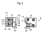
- Part 10 is in the form of an elongated block, made in one piece and having a plane face 26 (see Fig. 2).
- Part 12 is in the form of an elongated plate-like element having a plane face 28. When the nozzle is correctly closed, surfaces 26 and 28 make face to face contact and form a seal against passage of texturizing fluid between them.
- Part 10 has a groove 34 in surface 26 extending from one end of the block (the "downstream” end).
- Part 12 has a groove 36 in surface 28, extending from one end to the other of the plate element and being slightly widened at its upstream end (see Fig. 1).
- surfaces 26 and 28 are brought into correct engagement, grooves 34 and 36 are aligned to provide a passage extending from end to end through the nozzle but of varying cross-section therealong.
- This passage defines a thread path through the nozzle, various details of which can be obtained from the prior applications.
- Treatment fluid is fed into the passage at a junction location 42 (Fig. 1) atwhich the thread and the fluid are brought together.
- the treatment fluid is fed to the junction location by way of a bore 52 in part 10 leading to a chamber 54 and thence by way of a metering tube 56 to the junction location.
- Chamber 54 opens on to the upstream end of the block, and is closed in use by a closure plate 63 which can be removed to give access to the chamber and the metering tube 56.
- Tube 56 is retained in the desired position by means of a compression spring 60 extending between the closure 63 and the tube.
- a thread guide 61 secured to the closure 63, assists in guiding a thread correctly into the passage.
- a texturizing chamber (details not shown) is provided adjacent the downstream end of the thread passage by suitable formation of the block 10 and plate 12 as shown in European Application 108205 referred to above. Treatment fluid is permitted to leave the texturizing chamber transversly of the thread path and passes into an out-flow port 72 (in block 10) which contains a flow-controlling throttle 76.
- the plate element 12 is mounted on a plate-mounting structure generally indicated by numeral 120.
- This structure comprises a box-like support and housing portion 122.
- portion 122 is open-sided on its side facing block 10 and the plate-element 12 is located to "cover" this open side of portion 122.
- Element 12 is retained relative to portion 122 by means of four retaining devices 124 (one only visible in Fig. 1) adjacent respective corners.
- Each retaining device comprises a sleeve 126 with an internal screw thread and a pair of screws entering the sleeve from opposite ends thereof.
- the retaining effect of devices 124 permits some relative movement between element 12 and portion 122.
- a clearance is left between element 12 and the sleeve 126 of each retaining device 124, and a compression spring 128 is provided between the head of one screw and an abutment surface in the portion 122.
- a transverse partition 130 (Fig. 1).
- the chamber 132 which is at the upper end of the nozzle as viewed in Fig. 1, together with the contents thereof, will be described in detail.
- the lower chamber 134, and the contents thereof, are substantially the same, and will not be described separately.
- a through-bore 136 (Fig. 2) extends transversly through portion 122 at right angles to the thread passage and substantially parallel to the faces 26 and 28. Bore 136 is so located thatthe longitudinal axis thereof lies approximately in the plane of the surface defining the "back" of the chamber 132, that is the surface opposite the open "front” side of the chamber.
- a cylindrical pin 138 is located, for example by a press fit, in the bore 136 so that the pin extends across the whole width of chamber 132 (Fig. 2). Seated on pin 138 is a pair of levers 140, 142 respectively, both of which are visible in Fig. 2 but only one of which can be seen in Fig. 1.
- Each lever 140, 142 is in the form of a rectangular bar, and the levers are disposed (as best seen in Fig. 2) adjacent respective side walls of the chamber 132.
- Each bar has a semi-circular recess corresponding to the pin 138, and when seated on the pin each bar is spaced slightly from the back surface of chamber 132. Thus, the bars are free to pivot slightly about the longitudinal axis of pin 138.
- Bars 140, 142 are joined at their upper ends by a pin 144, and at their lower ends by a pin 146, each of these pins having a longitudinal axis parallel to the longitudinal axis of pin 138.
- Seated on pin 144 is a lever 148, and seated on pin 146 is a lever 150.
- Levers 148, 150 each have a semi-circular recess corresponding to the respective pins 144, 146, and each has at its upper and lower ends respectively a forwardly projecting abutment portion 152. As can be seen in both Figures, the abutment portions 152 project beyond the front, open side of portion 122, whereas all other parts of the lever structure remain within the chamber 132.
- Abutment portions 152 engage the reverse face of plate 12 so that a gap 154 is left between the plate and the front edge of support portion 120.
- Each lever 148, 150 is free to pivot about the longitudinal axis of its pin 144 or 146 until each of the abutment portions 152 engages the reverse face of plate 12.
- the overall external dimensions of the combination of the plate 12 and its support 120 correspond very closely with those of the block 10.
- support 120 is provided with suitable openings 154' for cooperation with retaining elements (not shown) of the mounting system which can be identical with that shown in Application 108 205.
- This exchangeability of part types is not, of course, essential but does enable substitution of the combination 12, 120 in existing nozzle structures.
- a locating pin 158 on plate 12 enters a locating opening 160 in block 10 to ensure the required alignment of grooves 34, 36 to form the thread passage.
- pin 158 is hidden behind element 156 on plate 12.
- the material and the dimensions of plate 12 are so selected in relation to the closing forces applied by the closing system that the plate is elastically deformable under those forces when surface 28 is driven against surface 26. Elastic deformation is hindered only in those regions in which the plate is contacted by the abutments 152, that is in eight specific contact regions (four associated with the upper chamber 132 and four with the lower chamber 134).
- the arrangement of levers within each chamber is such that each abutment 152 achieves a predetermined area of contact with the plate 12 and that the closing forces are evenly distributed between these eight contact areas.
- each contact area straddles the thread path as viewed in a direction normal to the contact area. Accordingly, the closing force is applied in regions immediately bordering on the grooves 34, 36 and at a plurality of intervals spaced along the length of the thread path.
- the adjustable mounting provided by the lever systems within housing 122 also permit some adjustment of plate 12 relative to block 10 during the closing movement even without flexing of the plate.
- Such adjustment has already been referred to in European Patent Application 110 359, and said application also shows a mounting system for blocks (such as block 10 and a combination 12, 120) to enable the mounting system to take up manufacturing and assembly inaccuracies. It may be found appropriate to arrange the mounting system to take up coarse inaccuracies, and to provide flexibility in plate 12 sufficient to enable fine adjustments to ensure sealing contact.
- Plate 12 is preferably of metal and, for reasons given further below, preferably has excellent heat conducting properties. In order to provide the plate with the maximum possible flexibility, it is preferably made as thin as possible while leaving adequate strength for the plate to absorb the closing forces even after formation of the groove 36.
- the heat flow properties of the combination 12, 120 are quite clearly different from those of, say, the block 12 shown in European Patent Application 108 205. The provision of the chambers 132, 134 substantially reduces the cross section available for heat flow in the combination 12, 120.
- the invention has been described by reference to a texturizing nozzle, particularly one in accordance with prior patent applications.
- the invention is not, however, limited to such use. It can be applied in any thread treating nozzle, for example a nozzle for applying twist to thread or for creating so called “entanglements" (an “interlacing” nozzle), or even a nozzle for simple forwarding of a thread.
- the invention is considered to have its most useful application in texturizing nozzles where very considerable pressures of thread treating medium (for example air or steam) are encountered.
Landscapes
- Engineering & Computer Science (AREA)
- Physics & Mathematics (AREA)
- Fluid Mechanics (AREA)
- Mechanical Engineering (AREA)
- Textile Engineering (AREA)
- Coating Apparatus (AREA)
- Yarns And Mechanical Finishing Of Yarns Or Ropes (AREA)
- Nonwoven Fabrics (AREA)
- Spinning Methods And Devices For Manufacturing Artificial Fibers (AREA)
- Treatment Of Fiber Materials (AREA)
Claims (24)
Applications Claiming Priority (2)
| Application Number | Priority Date | Filing Date | Title |
|---|---|---|---|
| US67759184A | 1984-12-03 | 1984-12-03 | |
| US677591 | 1984-12-03 |
Publications (4)
| Publication Number | Publication Date |
|---|---|
| EP0184625A2 EP0184625A2 (de) | 1986-06-18 |
| EP0184625A3 EP0184625A3 (en) | 1987-07-22 |
| EP0184625B1 EP0184625B1 (de) | 1990-05-16 |
| EP0184625B2 true EP0184625B2 (de) | 1993-09-08 |
Family
ID=24719357
Family Applications (1)
| Application Number | Title | Priority Date | Filing Date |
|---|---|---|---|
| EP19850112265 Expired - Lifetime EP0184625B2 (de) | 1984-12-03 | 1985-09-27 | Garnbehandlungsdüse |
Country Status (3)
| Country | Link |
|---|---|
| EP (1) | EP0184625B2 (de) |
| JP (1) | JP2664138B2 (de) |
| DE (1) | DE3577733C5 (de) |
Families Citing this family (7)
| Publication number | Priority date | Publication date | Assignee | Title |
|---|---|---|---|---|
| GB2193232A (en) * | 1986-06-17 | 1988-02-03 | Rieter Ag Maschf | Thread treating nozzles |
| DE3627513C2 (de) * | 1986-08-13 | 1996-09-19 | Barmag Barmer Maschf | Düse zum Texturieren eines laufenden Fadens |
| CH679785A5 (de) * | 1989-12-14 | 1992-04-15 | Rieter Ag Maschf | |
| DE19548361A1 (de) * | 1995-02-16 | 1996-08-22 | Rieter Ag Maschf | Fadenbehandlungsdüse |
| ATE208791T1 (de) | 1996-04-23 | 2001-11-15 | Biosearch Italia Spa | Chemisches verfahren zur herstellung von amidderivaten von a 40926 antibiotikum |
| TW538153B (en) † | 1998-03-03 | 2003-06-21 | Heberlein Fibertechnology Inc | Process for air-jet texturing of frill yarn and yarn-finishing device and the application thereof |
| GB0000786D0 (en) * | 2000-01-14 | 2000-03-08 | Univ Manchester | Apparatus for processing textile materials |
Family Cites Families (7)
| Publication number | Priority date | Publication date | Assignee | Title |
|---|---|---|---|---|
| US2938257A (en) * | 1957-07-23 | 1960-05-31 | American Viscose Corp | Bulked yarn manufacture |
| GB872234A (en) * | 1959-04-24 | 1961-07-05 | Canadian Celanese Ltd | Apparatus for the production of bulky yarns |
| US3237269A (en) * | 1963-09-26 | 1966-03-01 | Du Pont | Yarn bulking jet |
| US3261071A (en) * | 1965-05-25 | 1966-07-19 | Du Pont | Yarn treating jet |
| ATE35295T1 (de) * | 1979-10-02 | 1988-07-15 | Rieter Ag Maschf | Einfaedeln von garnbehandlungsduesen. |
| DE3172185D1 (en) * | 1980-03-31 | 1985-10-17 | Rieter Ag Maschf | Thread texturising nozzle |
| EP0108205A1 (de) * | 1982-10-12 | 1984-05-16 | Maschinenfabrik Rieter Ag | Luftdüse für Garnbehandlung |
-
1985
- 1985-09-27 DE DE3577733T patent/DE3577733C5/de not_active Expired - Lifetime
- 1985-09-27 EP EP19850112265 patent/EP0184625B2/de not_active Expired - Lifetime
- 1985-12-02 JP JP60269545A patent/JP2664138B2/ja not_active Expired - Lifetime
Also Published As
| Publication number | Publication date |
|---|---|
| EP0184625A2 (de) | 1986-06-18 |
| EP0184625B1 (de) | 1990-05-16 |
| DE3577733D1 (de) | 1990-06-21 |
| JPS61138738A (ja) | 1986-06-26 |
| DE3577733C5 (de) | 2010-12-30 |
| JP2664138B2 (ja) | 1997-10-15 |
| EP0184625A3 (en) | 1987-07-22 |
Similar Documents
| Publication | Publication Date | Title |
|---|---|---|
| US4364156A (en) | Apparatus for heated pressurized fluid stream treatment of substrate material | |
| EP0184625B2 (de) | Garnbehandlungsdüse | |
| US4393562A (en) | Apparatus for imparting visual surface effects to relatively moving materials | |
| EP0110359B1 (de) | Einfädeln von Garnbehandlungsdüsen | |
| US4326916A (en) | Breast box nozzle for a paper machine | |
| DE107605T1 (de) | Vorrichtung zur durchflussregelung. | |
| DE69509699T2 (de) | Ventilanschnittsystem vom Typ Rücken-an-Rücken | |
| US5395653A (en) | Apparatus and method for controlling coating frowns in hopper coating | |
| EP0123829B1 (de) | Garntexturierungsdüse | |
| CA2044970C (en) | Stationary support device for drainage wire | |
| US4941242A (en) | Thread treating nozzles | |
| US4936000A (en) | Lacing up of thread treating nozzles | |
| EP0831973B1 (de) | Abstützsystem für das dosierelement einer beschichtungsvorrichtung | |
| EP0059029B1 (de) | Vorrichtung zum Herstellen von visuellen Effekten auf den Oberflächen bewegender Materialien | |
| EP0249804B1 (de) | Behandlungsdüsen für Fäden | |
| US5581859A (en) | Thread treating nozzle with elastic plate | |
| WO1998057792A1 (en) | Flow control device and apparatus for mounting same | |
| KR100394407B1 (ko) | 액상물의 와이퍼 장치 | |
| KR100326650B1 (ko) | 압연스트립냉각장치 | |
| US4620899A (en) | Breast box nozzle for a paper machine | |
| EP0108705A2 (de) | Vorrichtung zum Kräuseln von textilen Fasermaterialien | |
| EP0108205A1 (de) | Luftdüse für Garnbehandlung | |
| EP1268908B1 (de) | Bemusterungsvorrichtung | |
| JPS60239560A (ja) | 織物のウエブのためのテンタ | |
| US6068736A (en) | Slice lip clamp assembly for a slice lip of a headbox |
Legal Events
| Date | Code | Title | Description |
|---|---|---|---|
| PUAI | Public reference made under article 153(3) epc to a published international application that has entered the european phase |
Free format text: ORIGINAL CODE: 0009012 |
|
| AK | Designated contracting states |
Kind code of ref document: A2 Designated state(s): CH DE FR GB IT LI |
|
| 17P | Request for examination filed |
Effective date: 19860712 |
|
| PUAL | Search report despatched |
Free format text: ORIGINAL CODE: 0009013 |
|
| AK | Designated contracting states |
Kind code of ref document: A3 Designated state(s): CH DE FR GB IT LI |
|
| 17Q | First examination report despatched |
Effective date: 19880914 |
|
| GRAA | (expected) grant |
Free format text: ORIGINAL CODE: 0009210 |
|
| AK | Designated contracting states |
Kind code of ref document: B1 Designated state(s): CH DE FR GB IT LI |
|
| REF | Corresponds to: |
Ref document number: 3577733 Country of ref document: DE Date of ref document: 19900621 |
|
| ITF | It: translation for a ep patent filed | ||
| ET | Fr: translation filed | ||
| PLBI | Opposition filed |
Free format text: ORIGINAL CODE: 0009260 |
|
| 26 | Opposition filed |
Opponent name: BARMAG AKTIENGESELLSCHAFT Effective date: 19910214 |
|
| PUAH | Patent maintained in amended form |
Free format text: ORIGINAL CODE: 0009272 |
|
| STAA | Information on the status of an ep patent application or granted ep patent |
Free format text: STATUS: PATENT MAINTAINED AS AMENDED |
|
| 27A | Patent maintained in amended form |
Effective date: 19930908 |
|
| AK | Designated contracting states |
Kind code of ref document: B2 Designated state(s): CH DE FR GB IT LI |
|
| ITTA | It: last paid annual fee | ||
| REG | Reference to a national code |
Ref country code: CH Ref legal event code: AEN |
|
| ITF | It: translation for a ep patent filed | ||
| ET3 | Fr: translation filed ** decision concerning opposition | ||
| PGFP | Annual fee paid to national office [announced via postgrant information from national office to epo] |
Ref country code: GB Payment date: 19950811 Year of fee payment: 11 |
|
| PG25 | Lapsed in a contracting state [announced via postgrant information from national office to epo] |
Ref country code: GB Effective date: 19960927 |
|
| GBPC | Gb: european patent ceased through non-payment of renewal fee |
Effective date: 19960927 |
|
| PGFP | Annual fee paid to national office [announced via postgrant information from national office to epo] |
Ref country code: FR Payment date: 20000828 Year of fee payment: 16 |
|
| PG25 | Lapsed in a contracting state [announced via postgrant information from national office to epo] |
Ref country code: FR Free format text: LAPSE BECAUSE OF NON-PAYMENT OF DUE FEES Effective date: 20020531 |
|
| REG | Reference to a national code |
Ref country code: FR Ref legal event code: ST |
|
| PGFP | Annual fee paid to national office [announced via postgrant information from national office to epo] |
Ref country code: DE Payment date: 20040907 Year of fee payment: 20 |
|
| PGFP | Annual fee paid to national office [announced via postgrant information from national office to epo] |
Ref country code: CH Payment date: 20040909 Year of fee payment: 20 |
|
| REG | Reference to a national code |
Ref country code: CH Ref legal event code: PL |