EP0184496B1 - Water injection device for a steam iron - Google Patents
Water injection device for a steam iron Download PDFInfo
- Publication number
- EP0184496B1 EP0184496B1 EP85402276A EP85402276A EP0184496B1 EP 0184496 B1 EP0184496 B1 EP 0184496B1 EP 85402276 A EP85402276 A EP 85402276A EP 85402276 A EP85402276 A EP 85402276A EP 0184496 B1 EP0184496 B1 EP 0184496B1
- Authority
- EP
- European Patent Office
- Prior art keywords
- skirt
- lip
- plunger
- needle
- injection
- Prior art date
- Legal status (The legal status is an assumption and is not a legal conclusion. Google has not performed a legal analysis and makes no representation as to the accuracy of the status listed.)
- Expired
Links
Images

Classifications
-
- D—TEXTILES; PAPER
- D06—TREATMENT OF TEXTILES OR THE LIKE; LAUNDERING; FLEXIBLE MATERIALS NOT OTHERWISE PROVIDED FOR
- D06F—LAUNDERING, DRYING, IRONING, PRESSING OR FOLDING TEXTILE ARTICLES
- D06F75/00—Hand irons
- D06F75/08—Hand irons internally heated by electricity
- D06F75/10—Hand irons internally heated by electricity with means for supplying steam to the article being ironed
- D06F75/14—Hand irons internally heated by electricity with means for supplying steam to the article being ironed the steam being produced from water in a reservoir carried by the iron
- D06F75/18—Hand irons internally heated by electricity with means for supplying steam to the article being ironed the steam being produced from water in a reservoir carried by the iron the water being fed slowly, e.g. drop by drop, from the reservoir to a steam generator
Landscapes
- Engineering & Computer Science (AREA)
- Textile Engineering (AREA)
- Irons (AREA)
- Nozzles (AREA)
Description
La présente invention concerne un dispositif d'injection pour fer à repasser à vapeur. Ce dispositif comprend plus particulièrement un ajutage monté dans une ouverture d'une paroi séparant un réservoir d'eau et une chambre de vaporisation située en service en dessous du réservoir. L'ajutage comporte une lèvre annulaire délimitant un orifice de communication entre le réservoir et la chambre, et une jupe entourant le passage d'écoulement en aval de la lèvre relativement au sens de l'écoulement. Le dispositif comprend d'autre part un pointeau présentant un évidement latéral et déplaçable axialement dans l'orifice entre une position de fermeture où la lèvre entoure le pointeau entre une extrémité libre de ce dernier et l'évidement latéral, et une position d'injection où la lèvre entoure le pointeau entre les deux extrémités axiales de l'évidement latéral.The present invention relates to an injection device for a steam iron. This device more particularly comprises a nozzle mounted in an opening in a wall separating a water tank and a vaporization chamber located in service below the tank. The nozzle comprises an annular lip delimiting a communication orifice between the reservoir and the chamber, and a skirt surrounding the flow passage downstream of the lip relative to the direction of flow. The device further comprises a needle having a lateral recess and movable axially in the orifice between a closed position where the lip surrounds the needle between a free end of the latter and the lateral recess, and an injection position where the lip surrounds the needle between the two axial ends of the lateral recess.
Un tel dispositif est connu du FR-A- 2 449 157. Lorsque le pointeau passe de l'une à l'autre de ses positions extrêmes, il fait travailler la lèvre en flexion, ce qui la détartre. La région lisse étant en service en dessous de l'évidement axial, on peut faire passer le pointeau en position d'injection par simple pression vers le bas, ce qui est commode.Such a device is known from FR-A-2 449 157. When the needle passes from one to the other of its extreme positions, it makes the lip work in flexion, which descales it. The smooth region being in service below the axial recess, the needle can be passed into the injection position by simple downward pressure, which is convenient.
Cette construction simple a cependant l'inconvénient qu'une gaine de tartre tend à se former sous la lèvre autour de la région lisse du pointeau. Dans un tel cas, même si l'utilisateur met le pointeau en position d'injection, la région lisse du pointeau, jointivement entourée par la gaine de tartre, empêche l'eau d'atteindre la chambre de vaporisation. Si le pointeau reste longtemps en position d'injection, il peut même arriver que le tartre le bloque dans cette position.This simple construction has the disadvantage, however, that a tartar sheath tends to form under the lip around the smooth region of the needle. In such a case, even if the user places the needle in the injection position, the smooth region of the needle, joined together by the tartar sheath, prevents water from reaching the vaporization chamber. If the needle remains in the injection position for a long time, it may even happen that the tartar blocks it in this position.
On connaît d'après le CH-A- 448 004 un dispositif d'injection dont l'ajutage comprend un siège conique concave suivi du côté inférieur par un orifice cylindrique calibré. Une soupape mobile selon l'axe de l'ajutage coopère avec le siège et porte en outre une aiguille engagée dans l'orifice calibré lorsque la soupape est en position de fermeture. Quand la soupape est au contraire décollée de son siège, l'aiguille est au-dessus de l'orifice et l'eau s'écoule en principe selon un débit déterminé par le calibrage de l'orifice. Lorsque la soupape retourne en position de fermeture, l'aiguille pousse vers le bas le dépôt de tartre qui a pu se former dans l'orifice, et empêche que l'orifice soit ensuite complètement occupé par du tartre si le dispositif n'est pas actionné pendant un certain temps. Pour remédier à la difficulté qu'il pourrait y avoir à manoeuvrer la soupape si le tartre forme une pellicule adhérente entre l'aiguille et l'orifice, il est prévu à l'extrémité de l'aiguille un renflement sphérique qui se trouve au-delà de l'orifice lorsque la soupape est fermée. Lorsque l'utilisateur ouvre à nouveau la soupape, le renflement est censé parcourir l'orifice en le dégageant de son tartre. Ceci est cependant peu efficace. En effet, si le tartre freine l'aiguille dans l'orifice, le renflement est difficile, voire impossible à engager dans l'orifice. De plus, si au lieu d'être simplement freinée, l'aiguille est bloquée dans l'orifice, le renflement, situé au-delà de l'orifice, ne peut avoir aucune action. Enfin, à supposer que le renflement remplisse son rôle, il fait remonter le tartre dans la région du siège ; ensuite, ou bien le tartre nuira à l'étanchéité en position de fermeture, ou bien il retombera dans l'orifice et réentartrera immédiatement ce dernier.According to CH-A-448 004, an injection device is known, the nozzle of which comprises a concave conical seat followed on the lower side by a calibrated cylindrical orifice. A valve movable along the axis of the nozzle cooperates with the seat and further carries a needle engaged in the calibrated orifice when the valve is in the closed position. When the valve is instead detached from its seat, the needle is above the orifice and the water flows in principle at a flow rate determined by the calibration of the orifice. When the valve returns to the closed position, the needle pushes down the scale deposit that may have formed in the orifice, and prevents the orifice from being completely occupied by scale if the device is not operated for a while. To overcome the difficulty that there may be in operating the valve if the tartar forms an adherent film between the needle and the orifice, there is provided at the end of the needle a spherical bulge which is located beyond the port when the valve is closed. When the user opens the valve again, the bulge is supposed to run through the orifice, freeing it from its tartar. This is however not very effective. Indeed, if the tartar slows the needle in the orifice, the bulge is difficult, even impossible to engage in the orifice. In addition, if instead of being simply braked, the needle is blocked in the orifice, the bulge, located beyond the orifice, can have no action. Finally, assuming that the bulge fulfills its role, it causes the tartar to rise in the region of the seat; then either the tartar will damage the seal in the closed position, or it will fall back into the orifice and immediately re-scale it.
Le but de l'invention est ainsi de proposer un dispositif d'injection du genre énoncé au début, par lequel la gaine de tartre susceptible d'entourer la région lisse du pointeau soit efficacement éliminée.The object of the invention is thus to propose an injection device of the kind stated at the beginning, by which the tartar sheath capable of surrounding the smooth region of the needle is effectively eliminated.
Suivant l'invention, le dispositif d'injection d'eau est caractérisé en ce que la jupe est souple et en ce que le pointeau porte axialement au-delà de sa région lisse un renflement entouré par la jupe en position de fermeture du pointeau.According to the invention, the water injection device is characterized in that the skirt is flexible and in that the needle carries axially beyond its smooth region a bulge surrounded by the skirt in the closed position of the needle.
Grâce à la souplesse de la jupe, le tartre ne bloque jamais complètement le pointeau. Si le pointeau est manoeuvré vers sa position de fermeture alors qu'un dépôt de tartre l'entoure à l'intérieur de la jupe, le renflement tend à entraîner le tartre avec le pointeau. S'il y a résistance, cette sollicitation déforme la jupe ce qui favorise l'éclatement de la couche de tartre et son décollement relativement à la jupe. Les fragments de tartre tombent et ne pourront donc plus ultérieurement revenir s'interposer dans l'ajutage.Thanks to the flexibility of the skirt, tartar never completely blocks the needle. If the needle is maneuvered towards its closed position while a deposit of tartar surrounds it inside the skirt, the bulge tends to entail tartar with the needle. If there is resistance, this bias deforms the skirt which promotes the bursting of the tartar layer and its detachment relative to the skirt. The fragments of tartar fall off and can therefore no longer be returned to the nozzle.
D'autres particularités et avantages de l'invention ressortiront encore de la description ci-après.Other features and advantages of the invention will emerge from the description below.
Aux dessins annexés, donnés à titre d'exemples non limitatifs :
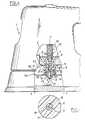
- - la figure 1 est une vue partielle en élévation latérale d'un fer à repasser selon l'invention, avec coupe axiale du dispositif d'injection d'eau ;
- - la figure 2 est une vue du dispositif d'injection en coupe selon le plan II-II de la figure 1 ;
- - la figure 3 est une vue du pointeau en coupe selon le plan III-III de la figure 1 ;
- - la figure 4 est une vue analogue à la figure 1 mais dans le cas où le pointeau est en position d'injection ; et
- - la figure 5 est une vue en coupe selon le plan V-V de la figure 4.
- - Figure 1 is a partial side elevational view of an iron according to the invention, with axial section of the water injection device;
- - Figure 2 is a view of the injection device in section along the plane II-II of Figure 1;
- - Figure 3 is a view of the needle in section along the plane III-III of Figure 1;
- - Figure 4 is a view similar to Figure 1 but in the case where the needle is in the injection position; and
- FIG. 5 is a sectional view along the plane VV of FIG. 4.
Dans l'exemple représenté aux figures, le fer à repasser comprend un boîtier en matière plastique 1 surmontant une semelle chauffante 2. Une chambre de vaporisation 3 est aménagée entre la face supérieure de la semelle chauffante 2 et une paroi en tôle métallique 6b. La semelle chauffante 2 est traversée par des ouïes de distribution de vapeur (non représentées) par lesquelles la chambre de vaporisation 3 communique avec l'extérieur, sous la semelle 2.In the example shown in the figures, the iron comprises a
Le boîtier 1 contient un réservoir d'eau 4 dont la paroi inférieure 6a, en tôle métallique, est située au-dessus de la paroi supérieure 6b de la chambre 3. Entre les parois 6a et 6b est ménagé un espace creux 6c, ayant pour but d'éviter l'échauffement de l'eau et la formation de vapeur dans le réservoir 4. Les parois 6a et 6b sont sensiblement horizontales dans la position de service du fer dans laquelle la semelle 2 est elle-même horizontale. Une ouverture 7 traverse les parois 6a et 6b. Dans celle-ci est monté l'ajutage 8 d'un dispositif d'injection d'eau 9 permettant sélectivement à l'eau contenue dans le réservoir 4 de passer goutte à goutte par gravité dans la chambre de vaporisation 3.The
L'ajutage 8 comprend un corps tubulaire 11 dont l'extrémité annulaire dirigée vers le réservoir 4 présente une collerette 12 s'appuyant, autour de l'ouverture 7, sous la tôle 6a adjacente au réservoir 4. La tôle 6a présente elle-même autour de l'ouverture 7 un rebord cylindrique 13 emboîté dans le corps 11. Un tube métallique 14 est serti par son extrémité dirigée vers la chambre 3 sur le bord que présente tout autour de l'ouverture 7 la tôle 6b adjacente à la chambre 3. Le tube 14 est emboîté sans jeu dans le corps 11 et s'étend jusqu'à une aile annulaire 16 du corps 11, dirigée radialement vers l'intérieur. Le corps 11 est ainsi centré par le rebord 13 et le tube 14, et il est positionné axialement entre le tube 14 et la tôle 6a.The
L'aile 16 porte une lèvre annulaire souple 17 délimitant par son bord libre un orifice circulaire 18 (figure 2). La lèvre 17 est décalée vers le réservoir 4 relativement à la tôle 6b de façon à être protégée autant que possible de la chaleur dégagée par la semelle chauffante 2. Sur sa face tournée vers la chambre de vaporisation 3, l'aile 16 porte à l'intérieur du tube métallique 14 une jupe 19 ayant une paroi intérieure cylindrique de diamètre supérieur à celui de l'orifice 18. Sur la majeure partie de sa longueur axiale, la jupe 19 est entourée par un espace libre 20 la séparant radialement du tube 14. L'espace 20 s'étend jusqu'à l'extrémité libre 33 que présente la jupe 19 vers la chambre 3, et communique ainsi avec la chambre 3 tout autour de la jupe 19. L'extrémité 33 de la jupe 19 dépasse du tube 14 vers la chambre de vaporisation 3. Le corps 11, la collerette 12, l'aile 16, la lèvre 17 et la jupe 19 sont réalisées en un seul bloc en résine silicone.The
Le dispositif d'injection 9 comprend en outre un pointeau 21 constitué par une tige de forme générale cylindrique réalisée en un matériau plastique résistant à la température. La tige 21 s'étend selon l'axe X-X de l'ajutage 8 et en particulier de l'orifice 18, cet axe étant perpendiculaire au plan des parois 6a et 6b et de la semelle chauffante 2. A son extrémité dirigée à l'opposé de la semelle 2, le pointeau 21 est fixé à un poussoir 22 monté à coulisse selon l'axe X-X dans un canon 23. Le poussoir 22 est relié à un bouton poussoir 24 faisant saillie au sommet du boîtier 1. Le pointeau 21 comporte au voisinage du poussoir 22 un évidement latéral 26 constitué par une rainure dirigée parallèlement à l'axe X-X. L'aire de la section de la rainure 26 considérée dans un plan perpendiculaire à l'axe X-X décroît en direction de la semelle chauffante 2. Ceci est visible aux figures 1 et 4 d'après la profondeur décroissante de la rainure 26. Entre sa rainure 26 et son extrémité libre 27 dirigée vers la semelle 2, le pointeau 21 présente une région cylindrique lisse 28. Le diamètre du pointeau 21 dans la région présentant la rainure 26 et dans la région 28 est supérieur au diamètre de l'orifice 18 avant montage du pointeau 21, et est inférieur au diamètre intérieur de la jupe 19.The
Par un dispositif de rappel à ressort non représenté, le pointeau 21 tend en permanence à revenir vers une position de fermeture (figure 1) dans laquelle la lèvre 17 entoure la région cylindrique lisse 28 du pointeau 21. Dans cette position, le pointeau 21 obture l'orifice 18 et empêche par conséquent l'écoulement d'eau vers la chambre de vaporisation 3.By a spring return device not shown, the
En pressant sur le bouton 24 (figure 4) l'utilisateur peut déplacer le pointeau 21 selon l'axe X-X jusqu'à ce que la lèvre 17 entoure le pointeau 21 dans la région présentant la rainure 26. Dès lors (figures 4 et 5) la rainure 26 permet à travers l'orifice 18 une fuite calibrée depuis le réservoir 4 vers la chambre de vaporisation 3. Compte tenu de la section non constante de la rainure 26, le débit vers la chambre de vaporisation 3 est d'autant plus important que le pointeau 21 est fortement déplacé vers la semelle 2, ce que l'utilisateur peut régler en appuyant plus ou moins sur le bouton 24.By pressing the button 24 (Figure 4) the user can move the
Dans un tel dispositif, la lèvre souple 17 est sollicitée en flexion par les mouvements axiaux du pointeau 21, ce qui la détartre. Comme l'extrémité libre 33 de la jupe 19 fait saillie vers la chambre de vaporisation 3, l'eau qui atteint l'extrémité 33 tombe dans la chambre 3 au lieu de se répandre latéralement vers le tube 14 et de former du tartre dans cette région. La formation de tartre est donc réduite. Si malgré cela il se forme à l'intérieur de la jupe 19 un dépôt tubulaire ayant en coupe la forme représentée en pointillés en 29 à la figure 1 et si aucune disposition n'est prise à l'encontre d'un fel dépôt 29, le pointeau 21 est freiné ou bloqué dans ses déplacements ; de plus, le dépôt de tartre peut réaliser l'étanchéité entre la jupe 19 et le pointeau 21 et ainsi empé- cher l'écoulement même lorsque le pointeau 21 est en position d'injection. Pour y remédier, on pourrait songer à disposer la lèvre 17 dans le plan de la tôle 6b, mais ceci aurait l'inconvénient de la soumettre davantage au chauffage par la semelle 2. De même, le pointeau 21 se rapprocherait trop de la semelle 2 en position d'injection.In such a device, the
Selon l'invention, la jupe 19 a en direction radiale une épaisseur lui permettant une certaine souplesse compte tenu de la matière (résine silicone) dans laquelle elle est réalisée. De plus, le pointeau 21 présente à son extrémité libre 27 dirigée vers la semelle 2, un renflement annulaire 31 ayant, en coupe selon un plan passant par l'axe X-X, une section en triangle isocèle dont la base est parallèle à l'axe X-X. Le diamètre extérieur du renflement 31 est inférieur au diamètre intérieur de la jupe 19. De préférence, le renflement 31 à un diamètre extérieur lui permettant de franchir la lèvre 17 par simple déformation élastique de cette dernière, ce qui permet de démonter le pointeau 21 par le haut pour son nettoyage.According to the invention, the
Lorsque le pointeau 21 est en position de fermeture, le renflement 31 est entouré par la jupe 19 (figure 1). De plus, la distance entre le renflement 31 et l'extrémité axiale 32 que présente la rainure 26 en direction du renflement 31 est supérieure ou égale (égale dans l'exemple représenté) à la distance entre la lèvre 17 et l'extrémité annulaire 33 que présente la jupe 19 du côté aval, c'est-à-dire vers la semelle 2. Ainsi, dès que la rainure 26 s'engage dans la lèvre 17, le renflement 31 sort de la jupe 19 et ne gêne donc pas l'écoulement le long de celle-ci.When the
Si, par exemple après une longue période d'injection, il s'est formé à l'intérieur de la jupe 19 le gros dépôt de tartre 29 représenté à la figure 1, et que l'utilisateur ramène le pointeau 21 en position de fermeture, le renflement 31 tend à entraîner le dépôt 29. Cette sollicitation déforme la jupe 19, ce qui craquelle le dépôt de tartre 29 et le décolle de la jupe 19. Les fragments décollés de la jupe 19 tombent sur la semelle 2, permettant le mouvement voulu du pointeau 21.If, for example after a long period of injection, a large deposit of
Les fragments de tartre se trouvent ainsi définitivement éloignés du dispositif d'injection. On donne ci-après un exemple numérique pour certaines dimensions du dispositif d'injection.
- - Diamètre du pointeau 21 : 4 mm
- - Diamètre extérieur du renflement 31 : 5 mm
- - Diamètre intérieur de la jupe 19 : 7 mm
- - Dimension axiale de la jupe 19 : 10 mm
- - Epaisseur de la jupe 19 : 1,5 mm.
- - Needle diameter 21: 4 mm
- - Outer diameter of the bulge 31: 5 mm
- - Inner diameter of the skirt 19: 7 mm
- - Axial dimension of the skirt 19: 10 mm
- - Thickness of the skirt 19: 1.5 mm.
Bien entendu, l'invention n'est pas limitée à l'exemple décrit et représenté. Au contraire, de nombreux aménagements peuvent être apportés à cet exemple sans sortir du cadre de l'invention.Of course, the invention is not limited to the example described and shown. On the contrary, numerous modifications can be made to this example without departing from the scope of the invention.
C'est ainsi que le renflement peut être situé en- deçà de l'extrémité libre du pointeau et il peut avoir un profil différent de celui décrit et représenté.Thus, the bulge can be located below the free end of the needle and it can have a profile different from that described and shown.
Claims (8)
Applications Claiming Priority (2)
| Application Number | Priority Date | Filing Date | Title |
|---|---|---|---|
| FR8417875 | 1984-11-23 | ||
| FR8417875A FR2573783B1 (en) | 1984-11-23 | 1984-11-23 | WATER INJECTION DEVICE FOR STEAM IRON |
Publications (2)
| Publication Number | Publication Date |
|---|---|
| EP0184496A1 EP0184496A1 (en) | 1986-06-11 |
| EP0184496B1 true EP0184496B1 (en) | 1988-05-04 |
Family
ID=9309881
Family Applications (1)
| Application Number | Title | Priority Date | Filing Date |
|---|---|---|---|
| EP85402276A Expired EP0184496B1 (en) | 1984-11-23 | 1985-11-22 | Water injection device for a steam iron |
Country Status (7)
| Country | Link |
|---|---|
| US (1) | US4669207A (en) |
| EP (1) | EP0184496B1 (en) |
| JP (1) | JPS61131800A (en) |
| CA (1) | CA1257533A (en) |
| DE (1) | DE3562495D1 (en) |
| ES (1) | ES290372Y (en) |
| FR (1) | FR2573783B1 (en) |
Families Citing this family (7)
| Publication number | Priority date | Publication date | Assignee | Title |
|---|---|---|---|---|
| FR2655667B1 (en) * | 1989-12-13 | 1992-02-21 | Seb Sa | WATER INJECTION DEVICE FOR STEAM IRON AND STEAM IRON COMPRISING SUCH A DEVICE. |
| DE4402683A1 (en) * | 1994-01-29 | 1995-08-03 | Braun Ag | Water inlet device for steam irons |
| US5623775A (en) * | 1996-01-16 | 1997-04-29 | Black & Decker Inc. | Electric steam iron with improved water tank and skirt assembly |
| US5829175A (en) * | 1996-09-20 | 1998-11-03 | Black & Decker Inc. | Steam iron with all temperature steam production |
| FR2776680B1 (en) * | 1998-03-27 | 2001-09-28 | Moulinex Sa | STEAM IRON |
| FR2802220B1 (en) * | 1999-12-14 | 2002-01-18 | Seb Sa | IRON BURNER WITH CERAMIC ROD |
| DE102007062015B4 (en) | 2007-12-21 | 2014-11-06 | BSH Bosch und Siemens Hausgeräte GmbH | Valve rod for irons |
Family Cites Families (14)
| Publication number | Priority date | Publication date | Assignee | Title |
|---|---|---|---|---|
| DE374847C (en) * | 1921-07-15 | 1923-05-02 | Otto Walker | Electric iron |
| FR602293A (en) * | 1925-08-19 | 1926-03-16 | Electric iron, with fabric humidification device | |
| US2746183A (en) * | 1951-02-21 | 1956-05-22 | Steam Iron Corp | Valve for steam iron |
| US2887799A (en) * | 1956-06-04 | 1959-05-26 | American Electrical Heater Co | Steam iron |
| FR1316012A (en) * | 1962-01-17 | 1963-01-25 | Jura Elektroapp Fabriken L Hen | Improvement in steam irons |
| CH448004A (en) * | 1965-12-09 | 1967-12-15 | Jura Elektroapparate Fab | Drip valve for steam iron |
| US3496661A (en) * | 1968-06-24 | 1970-02-24 | Gen Electric | Steam iron water valve structure |
| US3474552A (en) * | 1968-06-24 | 1969-10-28 | Gen Electric | Steam iron valve structure |
| CH564633A5 (en) * | 1972-03-21 | 1975-07-31 | Henzirohs L Jura Elektroappara | |
| US3758969A (en) * | 1972-03-27 | 1973-09-18 | Gen Electric | Fast start spray iron |
| US3849916A (en) * | 1972-11-10 | 1974-11-26 | Gen Electric | Self-cleaning steam iron |
| US3889406A (en) * | 1974-10-07 | 1975-06-17 | Hoover Co | Steam iron water valve and manual operating mechanism therefor |
| PT66021B (en) * | 1976-02-05 | 1978-06-19 | Rowenta Werke Gmbh | DRIP VALVE FOR STEAM BALL AUTOMATIC |
| FR2449157A1 (en) * | 1979-02-13 | 1980-09-12 | Seb Sa | WATER INJECTION DEVICE FOR STEAM IRON, AND STEAM IRON |
-
1984
- 1984-11-23 FR FR8417875A patent/FR2573783B1/en not_active Expired
-
1985
- 1985-11-18 ES ES1985290372U patent/ES290372Y/en not_active Expired
- 1985-11-19 CA CA000495645A patent/CA1257533A/en not_active Expired
- 1985-11-20 US US06/800,168 patent/US4669207A/en not_active Expired - Fee Related
- 1985-11-21 JP JP60259917A patent/JPS61131800A/en active Granted
- 1985-11-22 DE DE8585402276T patent/DE3562495D1/en not_active Expired
- 1985-11-22 EP EP85402276A patent/EP0184496B1/en not_active Expired
Also Published As
| Publication number | Publication date |
|---|---|
| JPS61131800A (en) | 1986-06-19 |
| US4669207A (en) | 1987-06-02 |
| DE3562495D1 (en) | 1988-06-09 |
| ES290372U (en) | 1986-10-16 |
| ES290372Y (en) | 1987-06-16 |
| FR2573783B1 (en) | 1987-03-20 |
| FR2573783A1 (en) | 1986-05-30 |
| CA1257533A (en) | 1989-07-18 |
| EP0184496A1 (en) | 1986-06-11 |
| JPS6344399B2 (en) | 1988-09-05 |
Similar Documents
| Publication | Publication Date | Title |
|---|---|---|
| EP0549397B1 (en) | Safety valve | |
| EP0184496B1 (en) | Water injection device for a steam iron | |
| EP0119181B1 (en) | Distributor or drip emitter for the microirrigation of soils | |
| EP0919171B1 (en) | Filter carrier for an expresso type coffee machine | |
| FR2825282A1 (en) | STOP VALVE FOR ENDOSCOPE WITH STOP ELEMENT | |
| EP2553301B1 (en) | Tap with delayed closing | |
| FR2712611A1 (en) | Steam generator for iron. | |
| EP1213038B1 (en) | Fire hose comprising a safety device to prevent it from moving under the action of water ensuring its feeding | |
| EP0486373A1 (en) | Drinker for cattle | |
| EP0575213B1 (en) | Dispensing device for liquid product | |
| FR2708209A1 (en) | Device for cleaning, especially for removing dust, for a spray | |
| EP1317575A2 (en) | Self-cleaning iron | |
| EP2101924B1 (en) | Portable sprayer | |
| EP0719969B1 (en) | Safety valve | |
| FR2660679A1 (en) | Control device with push-button and tilting cam for flushing mechanism | |
| FR2595783A1 (en) | Time-delayed tap with automatic closure of the valve | |
| FR2731260A1 (en) | Pressure balancing valve for a supply tank for hand-held tools | |
| EP0591087B1 (en) | Cut-off device for gas conduits under low or mean pressure | |
| BE1007021A3 (en) | HIGH PRESSURE JET DEVICE FOR SPRAYING LIQUIDS, AND PARTICULARLY FOR DECALAMINATING LAMINATED STEEL. | |
| EP0126667B1 (en) | Tube waterers for animals | |
| CH665347A5 (en) | Oral hygiene spray device - has spray head connectable to pressurised liq. supply, with selective control between multiple and single between multiple and single jets | |
| BE895982A (en) | MICRO-IRRIGATION, SELF-FILTERING, SELF-REGULATING AND SELF-CLEANING DISPENSER | |
| FR2561545A1 (en) | Hose-nozzle, especially for fire fighting | |
| EP1003409A1 (en) | Filter-holder provided with a beverage spill-proof device, and coffee maker equipped therewith | |
| BE535192A (en) |
Legal Events
| Date | Code | Title | Description |
|---|---|---|---|
| PUAI | Public reference made under article 153(3) epc to a published international application that has entered the european phase |
Free format text: ORIGINAL CODE: 0009012 |
|
| 17P | Request for examination filed |
Effective date: 19851127 |
|
| AK | Designated contracting states |
Kind code of ref document: A1 Designated state(s): BE DE FR GB IT LU NL |
|
| 17Q | First examination report despatched |
Effective date: 19870924 |
|
| ITF | It: translation for a ep patent filed |
Owner name: BARZANO' E ZANARDO ROMA S.P.A. |
|
| GRAA | (expected) grant |
Free format text: ORIGINAL CODE: 0009210 |
|
| AK | Designated contracting states |
Kind code of ref document: B1 Designated state(s): BE DE FR GB IT LU NL |
|
| REF | Corresponds to: |
Ref document number: 3562495 Country of ref document: DE Date of ref document: 19880609 |
|
| GBT | Gb: translation of ep patent filed (gb section 77(6)(a)/1977) | ||
| PLBE | No opposition filed within time limit |
Free format text: ORIGINAL CODE: 0009261 |
|
| STAA | Information on the status of an ep patent application or granted ep patent |
Free format text: STATUS: NO OPPOSITION FILED WITHIN TIME LIMIT |
|
| 26N | No opposition filed | ||
| PGFP | Annual fee paid to national office [announced via postgrant information from national office to epo] |
Ref country code: LU Payment date: 19910925 Year of fee payment: 7 |
|
| PGFP | Annual fee paid to national office [announced via postgrant information from national office to epo] |
Ref country code: BE Payment date: 19911024 Year of fee payment: 7 |
|
| ITTA | It: last paid annual fee | ||
| PGFP | Annual fee paid to national office [announced via postgrant information from national office to epo] |
Ref country code: NL Payment date: 19911130 Year of fee payment: 7 |
|
| EPTA | Lu: last paid annual fee | ||
| PG25 | Lapsed in a contracting state [announced via postgrant information from national office to epo] |
Ref country code: LU Free format text: LAPSE BECAUSE OF NON-PAYMENT OF DUE FEES Effective date: 19921122 |
|
| PG25 | Lapsed in a contracting state [announced via postgrant information from national office to epo] |
Ref country code: BE Effective date: 19921130 |
|
| BERE | Be: lapsed |
Owner name: S.A. SEB Effective date: 19921130 |
|
| PG25 | Lapsed in a contracting state [announced via postgrant information from national office to epo] |
Ref country code: NL Effective date: 19930601 |
|
| NLV4 | Nl: lapsed or anulled due to non-payment of the annual fee | ||
| REG | Reference to a national code |
Ref country code: GB Ref legal event code: IF02 |
|
| PGFP | Annual fee paid to national office [announced via postgrant information from national office to epo] |
Ref country code: FR Payment date: 20040913 Year of fee payment: 20 |
|
| PGFP | Annual fee paid to national office [announced via postgrant information from national office to epo] |
Ref country code: GB Payment date: 20041117 Year of fee payment: 20 |
|
| PGFP | Annual fee paid to national office [announced via postgrant information from national office to epo] |
Ref country code: DE Payment date: 20041208 Year of fee payment: 20 |
|
| PG25 | Lapsed in a contracting state [announced via postgrant information from national office to epo] |
Ref country code: GB Free format text: LAPSE BECAUSE OF EXPIRATION OF PROTECTION Effective date: 20051121 |
|
| REG | Reference to a national code |
Ref country code: GB Ref legal event code: PE20 |