EP0184489B1 - Pick-up draw-bar hitch - Google Patents
Pick-up draw-bar hitch Download PDFInfo
- Publication number
- EP0184489B1 EP0184489B1 EP85402200A EP85402200A EP0184489B1 EP 0184489 B1 EP0184489 B1 EP 0184489B1 EP 85402200 A EP85402200 A EP 85402200A EP 85402200 A EP85402200 A EP 85402200A EP 0184489 B1 EP0184489 B1 EP 0184489B1
- Authority
- EP
- European Patent Office
- Prior art keywords
- movable sleeve
- hook
- tractor
- coupling
- telescopic rods
- Prior art date
- Legal status (The legal status is an assumption and is not a legal conclusion. Google has not performed a legal analysis and makes no representation as to the accuracy of the status listed.)
- Expired - Lifetime
Links
Images

Classifications
-
- B—PERFORMING OPERATIONS; TRANSPORTING
- B60—VEHICLES IN GENERAL
- B60D—VEHICLE CONNECTIONS
- B60D1/00—Traction couplings; Hitches; Draw-gear; Towing devices
- B60D1/24—Traction couplings; Hitches; Draw-gear; Towing devices characterised by arrangements for particular functions
- B60D1/42—Traction couplings; Hitches; Draw-gear; Towing devices characterised by arrangements for particular functions for being adjustable
- B60D1/46—Traction couplings; Hitches; Draw-gear; Towing devices characterised by arrangements for particular functions for being adjustable vertically
- B60D1/465—Traction couplings; Hitches; Draw-gear; Towing devices characterised by arrangements for particular functions for being adjustable vertically comprising a lifting mechanism, e.g. for coupling while lifting
Definitions
- the invention relates to a movable sleeve coupling receiving any attachment system for trailers or other towed machinery, used on agricultural equipment and on public works machinery.
- a sheath capable of serving at the same time as a drawbar carrier, an oscillating bar carrier, a piton carrier or other attachment systems.
- drawbar carrier an oscillating bar carrier
- piton carrier a piton carrier
- sleeves are pivotally mounted about a fixed articulation axis, integral with the chassis. In this case, when the scabbard is in the low position, it drives the coupling system which it carries under the tractor.
- patent SE-B-312 730 which describes a coupling consisting of a frame to which is suspended a movable part articulated on two levers.
- This device makes it possible to lower using a cylinder mounted on the conventional lifting system of a tractor.
- the jack is oriented forward so that, combined with the path authorized by the levers, it raises the mobile part while keeping the hook in exactly the same vertical plane.
- the jack and the lifting system take up only the forces and shocks, when there is no immediate perfect alignment between the coupling and the trailer.
- Another drawback of this device is that of visibility for the user, because, when the hook descends, it is hidden by the frame and the chassis of the tractor; which does not facilitate positioning during attachment maneuvers.
- Patent GB-A-1,470,941 proposes a particular movable part, since it has locking hooks which come to block on the frame of the tractor.
- This movable part is pivotable on a single axis and it has the drawbacks of the devices of the prior art, namely masking of the hook during the attachment maneuvers, absence of buttressing with impact recovery on the pivot axis, shock and vibration fully transmitted to the tractor chassis.
- the present invention aims to remedy these drawbacks.
- the invention as characterized in the claims, solves the problem of obtaining that the sleeve follows a trajectory which makes it exit towards the rear of the tractor, by a pivoting combined with a translation, in order to bring it into low position and that it comes back to its place forward, under the tractor, when locking in the high position.
- the method of implementing a coupling with a movable sheath in combined rotation and translation, operated by the tractor lifting system and telescopic rods; this movable sheath being connected to the chassis of the tractor by two sets of rods of different lengths and comprising lifting pins coming to lock in retractable locking hooks integral with the upper part of the coupling, according to the invention is mainly characterized by what it consists of moving the movable sheath rearward when it is pivoted on the rods to reach the low position, determining the position of the hinge pins and the length of the rods as well as the travel of the telescopic rods of so as to obtain, in the low position of said movable sheath, a misalignment of the latter with the front links at an angle alpha, the apex of which is directed upwards, so as to obtain a bracing without recoil of the movable sheath, and , in the high position of the movable sheath, a plating thereof on elastic stops,
- the coupling with movable sheath in combined rotation and translation, operated by the tractor lifting system and telescopic rods, the movable sheath of which is connected to the tractor chassis by two sets of rods of different lengths, and comprising lifting crank pins blocking in retractable locking hooks secured to the upper part of the hitch is mainly characterized in that the displacement towards the rear of the movable sheath when pivoted on the rods to reach the low position, is obtained by means of the tractor lifting device and telescopic rods of adjustable length, in that the upward misalignment of the sheath movable relative to the front links at an obtuse angle alpha is determined by adjusting the maximum travel of the telescopic rods, in that the elastic stops are of such elasticity that unlocking can only be carried out under the action of the telescopic rods , in that the erasure of the locking hooks by the crank pins for lifting the movable shea
- the retractable locking hooks are permanently returned to the locking position by springs.
- the movable sheath is, in the locked position, completely situated under the rear part of the tractor and that it is immobilized against it by means of elastic stops eliminating the play and absorbing shocks and vibrations, while in the low position, it can, after locking, be moved back and lowered while respecting an inclination favorable to the attachment of the towed device and the transmission of the towing forces to the chassis of the tractor.
- This sheath is, moreover, fully visible from the tractor driving position, during the operations of hooking up and unhooking the towed equipment.
- the figures represent a movable sleeve hitch consisting mainly of an upper part 1, mounted at the rear end 2 of the chassis of a tractor under which elastic stops 3 and 4 are fixed and ears 5 and 6 with respect to which are articulated, via axes 7 and 8, the front links 9 and rear 10, of different lengths, supporting, by means of crank pins 11 and 12 the movable sheath 13, inside which is mounted a bar towing hook 25 hook 14.
- the movable sheath is maneuvered by means of the lifting device 15 of the tractor, telescopic rods, of adjustable length, 16 and crank pins 17.
- the movable sheath 13 is unlocked by prior compression of the elastic stops 3 and 4, by means of the lift 15 and the telescopic rods 16, then tilting of the hooks 18 under the action of the cable 31 and the lever 20.
- the two retractable hooks 18 are interconnected by a cross member 21 on which is fixed one end of the return spring 19. These mechanisms are protected by a housing 22.
- the oscillating bar 25 is retained inside the movable sheath 13 by means of the hook 14 with a removable axis 26 and a fixed axis forming a stop 27.
- the removable axis 26 can occupy a second position 26a, closer to the opening of the movable sheath 13; which provides two different ranges of travel. Other positions, allowing other deflections, can be envisaged.
- Figure 4 shows the movable sheath 13 equipped with the same oscillating bar 25 as that shown in Figure 3, but mounted in the hook position.
- the yoke 25b is introduced inside the movable sheath 13 and the oscillating bar is immobilized longitudinally by a removable axis 28 and laterally by the removable axis 26 and the fixed axis 27 forming a stop.
- the removable pin 28 is placed in the storage position in an orifice 13a disposed laterally in an area not swept by the oscillating bar.
- the sheath mobile 29 is reduced in thickness and the attachment device 30, with which it is equipped, is fixed on its rear part.
- the movable sheath 13 and the front links 9 are misaligned and form an angle a, the apex of which is directed upwards, so as to obtain a bracing, without recoil of the movable sheath 13, during a possible stress on the front of the tractor.
- This misalignment is limited by the adjustable travel of the telescopic rods 16.
- the angle a becomes greater than 180 °, which eliminates the bracing and allows the front and rear links to ensure their function.
- the elasticity of the elastic stops 3 and 4 is defined such that the unlocking can only be carried out under the action of the telescopic lifting rods and not under the action of the components of the forces applied.
Landscapes
- Engineering & Computer Science (AREA)
- Transportation (AREA)
- Mechanical Engineering (AREA)
- Agricultural Machines (AREA)
- Polishing Bodies And Polishing Tools (AREA)
- Tents Or Canopies (AREA)
- Mechanical Operated Clutches (AREA)
- Fittings On The Vehicle Exterior For Carrying Loads, And Devices For Holding Or Mounting Articles (AREA)
- Joints Allowing Movement (AREA)
- Mechanical Coupling Of Light Guides (AREA)
- Springs (AREA)
Abstract
Description
L'invention concerne un attelage à fourreau mobile recevant tout système d'accrochage pour remorques ou autres engins tractés, utilisés sur du matériel agricole et sur les engins de travaux publics.The invention relates to a movable sleeve coupling receiving any attachment system for trailers or other towed machinery, used on agricultural equipment and on public works machinery.
Il est connu d'assurer le déplacement de matériels roulants non motorisés, ou d'outils traînés, à l'aide de véhicules tracteurs équipés d'un système comportant soit un crochet, une barre d'attelage fixe ou oscillante, ou un piton.It is known to move non-motorized rolling stock, or trailed tools, using towing vehicles equipped with a system comprising either a hook, a fixed or oscillating drawbar, or a peg.
Il est connu aussi d'utiliser un fourreau capable de servir à la fois de porte-barre d'attelage, de porte-barre oscillante, de porte piton ou d'autres systèmes d'accrochage. Pour faciliter l'accrochage, de tels fourreaux sont montés pivotants autour d'un axe d'articulation fixe, solidaire du châssis. Dans ce cas, lorsque le fourreau est en position basse, il entraîne le système d'attelage qu'il porte sous le tracteur.It is also known to use a sheath capable of serving at the same time as a drawbar carrier, an oscillating bar carrier, a piton carrier or other attachment systems. To facilitate attachment, such sleeves are pivotally mounted about a fixed articulation axis, integral with the chassis. In this case, when the scabbard is in the low position, it drives the coupling system which it carries under the tractor.
Il existe divers moyens, connus de l'homme de l'art, permettant de faire effectuer à ce fourreau la trajectoire souhaitée, parmi lesquels figure un système de biellettes de longueurs différentes qui, lors de leur articulation, font effectuer un pivotement, accompagné d'une translation, au dispositif qu'elles supportent. Un tel moyen, décrit dans la norme française NF 4.140.32, est utilisé pour obtenir le pivotement du système de relevage arrière des tracteurs.There are various means, known to those skilled in the art, making it possible to carry out this sheath the desired trajectory, among which is a system of rods of different lengths which, during their articulation, cause a pivoting, accompanied by 'a translation, to the device they support. Such a means, described in French standard NF 4.140.32, is used to obtain the pivoting of the rear linkage system of tractors.
On connaît également le brevet SE-B-312 730 qui décrit un attelage constitué d'un bâti auquel est suspendu une partie mobile articulée sur deux leviers. Ce dispositif permet d'abaisser à l'aide d'un vérin monté sur le système classique de relevage d'un tracteur. Le vérin est orienté vers l'avant de telle façon que, combiné avec la trajectoire autorisée par les leviers, il relève la partie mobile en conservant le crochet exactement dans le même plan vertical. Par ailleurs, lors de l'accrochage, le vérin et le système de relevage reprennent seuls les efforts et les chocs, lorsqu'il n'y a pas alignement immédiat parfait entre l'attelage et la remorque.Also known is patent SE-B-312 730 which describes a coupling consisting of a frame to which is suspended a movable part articulated on two levers. This device makes it possible to lower using a cylinder mounted on the conventional lifting system of a tractor. The jack is oriented forward so that, combined with the path authorized by the levers, it raises the mobile part while keeping the hook in exactly the same vertical plane. In addition, during attachment, the jack and the lifting system take up only the forces and shocks, when there is no immediate perfect alignment between the coupling and the trailer.
Un autre inconvénient de ce dispositif est celui de la visibilité pour l'utilisateur, car, lorsque le crochet descend, il est masqué par le bâti et le châssis du tracteur; ce qui ne facilite pas le positionnement lors des manoeuvres d'accrochage.Another drawback of this device is that of visibility for the user, because, when the hook descends, it is hidden by the frame and the chassis of the tractor; which does not facilitate positioning during attachment maneuvers.
Le brevet GB-A-1 470 941 propose une partie mobile particulière, puisqu'elle présente des crochets de verrouillage qui viennent se bloquer sur le bâti du tracteur. Ainsi, les efforts après accrochage, sont supportés en totalité par le châssis du tracteur dans le plan vertical et, en partie, dans le plan horizontal, au lieu de les faire supporter par le seul système de relevage. Cette partie mobile est pivotante sur un seul axe et elle présente les inconvénients des dispositifs de l'art antérieur, à savoir masquage du crochet lors des manoeuvres d'accrochage, absence d'arc boutement avec reprise des chocs sur l'axe de pivotement, chocs et vibrations entièrement transmis au châssis du tracteur.Patent GB-A-1,470,941 proposes a particular movable part, since it has locking hooks which come to block on the frame of the tractor. Thus, the forces after hooking up, are supported entirely by the chassis of the tractor in the vertical plane and, in part, in the horizontal plane, instead of having them supported by the only lifting system. This movable part is pivotable on a single axis and it has the drawbacks of the devices of the prior art, namely masking of the hook during the attachment maneuvers, absence of buttressing with impact recovery on the pivot axis, shock and vibration fully transmitted to the tractor chassis.
La présente invention a pour but de remédier à ces inconvénients. L'invention, telle qu'elle est caractérisée dans les revendications, résout le problème consistant à obtenir que le fourreau suive une trajectoire qui le fasse sortie vers l'arrière du tracteur, par un pivotement combiné à une translation, pour l'amener en position basse et que celui-ci vienne reprendre sa place vers l'avant, sous le tracteur, lors de verrouillage en position haute.The present invention aims to remedy these drawbacks. The invention, as characterized in the claims, solves the problem of obtaining that the sleeve follows a trajectory which makes it exit towards the rear of the tractor, by a pivoting combined with a translation, in order to bring it into low position and that it comes back to its place forward, under the tractor, when locking in the high position.
Le procédé de mise en oeuvre d'un attelage à fourreau mobile en rotation et en translation combinées, manoeuvré par l'intermédiaire du système de relevage du tracteur et de tiges télescopiques; ce fourreau mobile étant relié au châssis du tracteur par deux jeux de biellettes du longueurs différentes et comportant des manetons de relevage venant se bloquer dans des crochets de verrouillage escamotables solidaires de la partie supérieure de l'attelage, selon l'invention se caractérisé principalement en ce qu'il consiste à faire déplacer le fourreau mobile vers l'arrière lors de son pivotement sur les biellettes pour rejoindre la position basse, à déterminer la position des axes d'articulation et la longueur des biellettes ainsi que le débattement des tiges télescopiques de façon à obtenir, en position basse du dit fourreau mobile, un désalignement de celui-ci avec les biellettes avant selon un angle alpha dont le sommet est dirigé vers le haut, de façon à obtenir un arc-boutement sans recul du fourreau mobile, et, en position haute du fourreau mobile, un placage de celui-ci sur des butées élastiques, lorsqu'il est soumis à un effort dirigé vers l'avant du tracteur, en ce qu'il consiste à faire assurer l'effacement des crochets de verrouillage par les manetons de relevage du fourreau mobile, en ce qu'il consiste, pour obtenir le déverrouillage du fourreau mobile à comprimer les butées élastiques par l'intermédiaire du relevage et des tiges télescopiques puis à faire basculer les crochets de verrouillage, en ce qu'il consiste à utiliser le crochet de la barre de remorquage oscillante pour solidariser celle-ci au fourreau lorsque la dite barre est utilisée en position chape, et en ce qu'il consiste à interdir la sortie intempestive de l'anneau de remorquage du crochet de remorquage lorsque la barre de remorquage est en position crochet et que le fourreau mobile est verrouillé en position haute.The method of implementing a coupling with a movable sheath in combined rotation and translation, operated by the tractor lifting system and telescopic rods; this movable sheath being connected to the chassis of the tractor by two sets of rods of different lengths and comprising lifting pins coming to lock in retractable locking hooks integral with the upper part of the coupling, according to the invention is mainly characterized by what it consists of moving the movable sheath rearward when it is pivoted on the rods to reach the low position, determining the position of the hinge pins and the length of the rods as well as the travel of the telescopic rods of so as to obtain, in the low position of said movable sheath, a misalignment of the latter with the front links at an angle alpha, the apex of which is directed upwards, so as to obtain a bracing without recoil of the movable sheath, and , in the high position of the movable sheath, a plating thereof on elastic stops, when it is subjected to a force directed towards the front d u tractor, in that it consists in ensuring the erasure of the locking hooks by the crank pins for lifting the mobile sheath, in that it consists, in order to obtain the unlocking of the mobile sheath, in compressing the elastic stops by the intermediate lifting and telescopic rods then to tilt the locking hooks, in that it consists in using the hook of the oscillating tow bar to secure it to the sheath when said bar is used in the clevis position, and in that it consists in prohibiting the untimely exit of the towing eye of the towing hook when the towing bar is in the hook position and the movable sheath is locked in the high position.
L'attelage à fourreau mobile en rotation et en translation combinées, manoeuvré par l'intermédiaire du système de relevage du tracteur et de tiges télescopiques dont le fourreau mobile est relié au châssis du tracteur par deux jeux de biellettes de longueurs différentes, et comportant des manetons de relevage venant se bloquer dans des crochets de verrouillage escamotables solidaires de la partie supérieure de l'attelage, dont la mise en oeuvre s'effectue selon le procédé faisant l'objet de l'invention se caractérisé principalement en ce que le déplacement vers l'arrière du fourreau mobile lors de son pivotement sur les biellettes pour rejoindre la position basse, est obtenu par l'intermédiaire du dispositif de relevage du tracteur et des tiges télescopies de longeueur réglable, en ce que le désalignement vers le haut du fourreau mobile par rapport aux biellettes avant selon un angle obtus alpha est déterminé par réglage du débattement maximum des tiges télescopiques, en ce que les butées élastiques sont d'une élasticité telle que le déverrouillage ne puisse s'effectuer que sous l'action des tiges télescopiques, en ce que l'effacement des crochets de verrouillage par les manetons de relevage du fourreau mobile est obtenu par l'intermédiaire d'une rampe dont est muni le bec du crochet de verrouillage en ce que le basculement des crochets de verrouillage pour obtenir la libération des manetons de relevage du fourreau est obtenu à distance par l'intermédiaire d'un câble et d'un levier, en ce que, en position chape, le crochet de la barre de remorquage oscillante est solidarisé au fourreau mobile par l'intermédiaire d'un axe fixe et d'un axe amovible passant par le bec du crochet et en ce que la sortie intempestive de l'anneau de remorquage du crochet de remorquage, lorsque la barre de remorquage est en position crochet et que le fourreau mobile est verrouillé en position haute, est interdite par une traverse située à l'extrémité arrière de la partie supérieure de l'attelage, juste au-dessus de l'ouverture du crochet.The coupling with movable sheath in combined rotation and translation, operated by the tractor lifting system and telescopic rods, the movable sheath of which is connected to the tractor chassis by two sets of rods of different lengths, and comprising lifting crank pins blocking in retractable locking hooks secured to the upper part of the hitch, the implementation of which is carried out according to the process forming the subject of the invention, is mainly characterized in that the displacement towards the rear of the movable sheath when pivoted on the rods to reach the low position, is obtained by means of the tractor lifting device and telescopic rods of adjustable length, in that the upward misalignment of the sheath movable relative to the front links at an obtuse angle alpha is determined by adjusting the maximum travel of the telescopic rods, in that the elastic stops are of such elasticity that unlocking can only be carried out under the action of the telescopic rods , in that the erasure of the locking hooks by the crank pins for lifting the movable sheath is obtained by means of a ramp which is fitted with the spout of the locking hook in that the tilting of the locking hooks to obtain the release of the sleeves for lifting the sheath is obtained remotely by means of a cable and a lever, in that, in the clevis position, the c ratchet of the oscillating tow bar is secured to the movable sheath by means of a fixed axis and a removable axis passing through the hook spout and in that the untimely exit of the towing eye from the tow hook , when the tow bar is in the hook position and the movable sheath is locked in the high position, is prohibited by a crossmember located at the rear end of the upper part of the hitch, just above the opening of the hook.
Les crochets de verrouillage escamobables sont rappelés en permanence en position de verrouillage par des ressorts.The retractable locking hooks are permanently returned to the locking position by springs.
Les avantages obtenus grâce à cette invention consistent essentiellement en ce que le fourreau mobile est, en position verrouillée, totalement situé sous la partie arrière du tracteur et qu'il est immobilisé contre cellel-ci par l'intermédiare de butées élastiques éliminant le jeu et absorbant les chocs et les vibrations, alors, qu'en position basse, il peut, après verrouillage, être reculé et abaissé en respectant une inclinaison favorable à l'accrochage du dispositif remorqué et à la transmission des efforts de remorquage au châssis du tracteur. Ce fourreau est, de plus, entièrement visible du poste de conduite du tracteur, lors des opérations d'accrochage et de décrochage du matériel remorqué.The advantages obtained thanks to this invention consist essentially in that the movable sheath is, in the locked position, completely situated under the rear part of the tractor and that it is immobilized against it by means of elastic stops eliminating the play and absorbing shocks and vibrations, while in the low position, it can, after locking, be moved back and lowered while respecting an inclination favorable to the attachment of the towed device and the transmission of the towing forces to the chassis of the tractor. This sheath is, moreover, fully visible from the tractor driving position, during the operations of hooking up and unhooking the towed equipment.
L'invention est exposée ci-après plus en détail à l'aide de dessins représentant seulement un mode de réalisation.
- La figure 1 représente, une vue de côté de l'attelage montrant le fourreau mobile en position verrouillée, avec indication de sa position basse et d'une position intermédiaire en trait Mixte.
- La figure 2 représente, une vue de l'arrière de l'attelage, montrant le fourreau mobile en position verrouillée, avec indication de sa position basse en traite mixte.
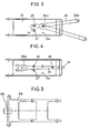
- La figure 3 représenté, une vue de dessus du fourreau mobile équipé d'une barre oscillante fixée par l'intermédiaire du crochet de remorquage.
- La figure 4 représente, une vue de dessus du fourreau mobile équipé d'une barre oscillante montée en position crochet.
- La figure 5 représente, une vue de dessus d'un fourreau d'épaisseur réduite équipé d'un crochet de remorquage.
- FIG. 1 represents a side view of the coupling showing the movable sheath in the locked position, with indication of its low position and of an intermediate position in phantom.
- 2 shows a view of the rear of the hitch, showing the movable sheath in the locked position, with an indication of its low position in mixed draft.
- Figure 3 shown, a top view of the movable sheath fitted with an oscillating bar fixed by means of the towing hook.
- FIG. 4 represents a top view of the movable sheath fitted with an oscillating bar mounted in the hook position.
- FIG. 5 represents a top view of a sheath of reduced thickness equipped with a tow hook.
Les figures représentent un attelage à fourreau mobile constitué principalement d'une partie supérieure 1, montée à l'extrémité arrière 2 du châssis d'un tracteur sous laquelle sont fixées des butées élastiques 3 et 4 et des oreilles 5 et 6 par rapport auxquelles sont articulées, par l'intermédiaire d'axes 7 et 8, les biellettes avant 9 et arrière 10, de longueurs différentes, supportant, par l'intermédiaire de manetons 11 et 12 le fourreau mobile 13, à l'intérieur duquel est monté une barre de remorquage 25 à crochet 14.The figures represent a movable sleeve hitch consisting mainly of an
La manoeuvre du fourreau mobile s'effectue par l'intermédiaire du dispositif de relevage 15 du tracteur, de tiges télescopiques, de longueur réglable, 16 et de manetons 17.The movable sheath is maneuvered by means of the
Le verrouillage du fourreau mobile 13 contre la partie supérieure 1 de l'attelage, avec déformation des butées élastiques 3 et 4, est obtenu par l'intermédiaire de crochets escamotables 18, rappelés en position verrouillée par un ressort 19, dont le bec est muni d'une rampe 18a permettant l'effacement sous l'action des manetons 17.The locking of the
Le déverrouillage du fourreau mobile 13 s'effectue, par compression préalable des butées élastiques 3 et 4, par l'intermédiaire du relevage 15 et des tiges télescopiques 16, puis basculement des crochets 18 sous l'action du câble 31 et du levier 20. Comme on le voit sur la figure 2 les deux crochets escamotables 18 sont reliés entre eux par une traverse 21 sur laquelle est fixée l'une des extrémités du ressort de rappel 19. Ces mécanismes sont protégés par un carter 22. Une traverse 23, située à l'extrémité arrière de la partie supérieure de l'attelage, située juste au dessus de l'ouverture 14a du crochet de remorquage 14, interdit la sortie du dit crochet, de l'anneau de remorquage 24.The
En examinant la figure 3, on remarque que la barre oscillante 25 est retenue à l'intérieur du fourreau mobile 13 par l'intermédiaire du crochet 14 d'un axe amovible 26 et d'un axe fixe formant butée 27. L'axe amovible 26 peut occuper une seconde position 26a, plus rapprochée de l'ouverture du fourreau mobile 13; ce qui permet d'obtenir deux amplitudes de débattement différentes. D'autres positions, permettant d'autres débattements, peuvent être envisagées.By examining FIG. 3, it can be seen that the oscillating
La figure 4 montre le fourreau mobile 13 équipé de la même barre oscillante 25 que celle représentée à la figure 3, mais montée en position crochet. Dans ce cas, la chape 25b est introduite à l'intérieur du fourreau mobile 13 et la barre oscillante est immobilisée longitudinalement par un axe amovible 28 et latéralement par l'axe amovible 26 et l'axe fixe 27 formant butée. En position barre osicllante l'axe amovible 28 est mis en position de stockage dans un orifice 13a disposé latéralement dans une zone non balayée par la barre oscillante.Figure 4 shows the
En examinant la figure 5 on remarque que, dans son mode de réalisation simplifié le fourreau mobile 29 est réduit d'épaisseur et que le dispositif d'accrochage 30, dont il est équipée, est fixé sur sa partie arrière.By examining FIG. 5, it can be seen that, in its simplified embodiment, the sheath mobile 29 is reduced in thickness and the
Comme on le voit en se reportant aux figures 1 et 2:As can be seen by referring to Figures 1 and 2:
En position basse, le fourreau mobile 13 et les biellettes avant 9 sont désalignés et forment un angle a, dont le sommet est dirigé vers le haut, de façon à obtenir un arc-boutement, sans recul du fourreau mobile 13, lors d'une éventuelle sollicitation vers l'avant du tracteur. Ce désalignement est limité par le débattement réglable des tiges télescopiques 16.In the low position, the
Lors d'une sollicitation du fourreau mobile 13 vers l'arrière du tracteur, il se produit une légère rotation, vers l'arrière, des biellettes arrière 10, jusqu'à obtention de l'alignement des biellettes avant 9 avec le fourreau mobile 13. L'angle a n'est que très légèrement inférieur à 180°, afin de réduire au minimum l'amplitude du débattement correspondant, tout en assurant la butée longitudinale par arc-boutement du fourreau mobile 13.When the moving
Au début de la remontée du fourreau mobile 13, sous faction, du relevage 15 et des tiges télescopiques 16, l'angle a devient supérieur à 180°, ce qui élimine l'arc-boutement et permet aux biellettes avant et arrière d'assurer leur fonction.At the start of the ascent of the
En position verrouillée, le fourreau mobile est plaqué contre les butées élastiques 3 et 4 sous l'action du crochet de verrouillage 18. Lors d'une sollicitation horizontale les composantes horizontales et verticales contribuent, par l'intermédiaire des biellettes, à plaquer le fourreau mobile 13 contre les butées élastiques 3 et 4. Cet effet est contrôlé par une légère inclinaison, vers le bas, des biellettes avant 9.In the locked position, the movable sheath is pressed against the
L'élasticité des butées élastiques 3 et 4 est définie de telle sorte que le déverrouillage ne puisse s'effectuer que sous l'action des tiges télescopiques de relevage et non sous l'action des composantes des efforts appliqués.The elasticity of the
Comme on le voit dans cet exemple l'utilisation de jeux de biellettes 9 et 10, de longueurs différentes, permet de faire suivre au fourreau mobile 13 ou 29, une trajectoire prédéterminée, combinant une rotation à une translation.As can be seen in this example, the use of sets of
Claims (3)
Priority Applications (1)
| Application Number | Priority Date | Filing Date | Title |
|---|---|---|---|
| AT85402200T ATE60549T1 (en) | 1984-11-16 | 1985-11-14 | MOVABLE TRAILER HITCH. |
Applications Claiming Priority (2)
| Application Number | Priority Date | Filing Date | Title |
|---|---|---|---|
| FR8417508 | 1984-11-16 | ||
| FR8417508A FR2573360B1 (en) | 1984-11-16 | 1984-11-16 | MOBILE SLEEVE HITCH |
Publications (2)
| Publication Number | Publication Date |
|---|---|
| EP0184489A1 EP0184489A1 (en) | 1986-06-11 |
| EP0184489B1 true EP0184489B1 (en) | 1991-01-30 |
Family
ID=9309667
Family Applications (1)
| Application Number | Title | Priority Date | Filing Date |
|---|---|---|---|
| EP85402200A Expired - Lifetime EP0184489B1 (en) | 1984-11-16 | 1985-11-14 | Pick-up draw-bar hitch |
Country Status (5)
| Country | Link |
|---|---|
| EP (1) | EP0184489B1 (en) |
| AT (1) | ATE60549T1 (en) |
| DE (2) | DE184489T1 (en) |
| ES (1) | ES290504Y (en) |
| FR (1) | FR2573360B1 (en) |
Cited By (1)
| Publication number | Priority date | Publication date | Assignee | Title |
|---|---|---|---|---|
| DE4130829A1 (en) * | 1991-09-17 | 1993-03-18 | Deere & Co | TOWING DEVICE FOR TRACTORS |
Families Citing this family (9)
| Publication number | Priority date | Publication date | Assignee | Title |
|---|---|---|---|---|
| FR2602721B1 (en) * | 1986-08-14 | 1988-11-25 | Lemoine Mecano Soudure | DEVICE FOR FIXING REVERSIBLE OSCILLATING BARS IN A MOBILE HARNESS HITCH |
| DE8807849U1 (en) * | 1988-06-16 | 1988-08-25 | Sauermann, Roman Johann, 8899 Freinhausen | Device for coupling a trailer to a vehicle |
| DE4201830A1 (en) * | 1992-01-24 | 1993-07-29 | Walterscheid Gmbh Jean | Trailer attachment frame for farm tractor - uses spiral cable to raise and lower frame |
| DE4208343A1 (en) * | 1992-03-16 | 1993-09-23 | Walterscheid Gmbh Jean | TOWING DEVICE WITH OPENING LOCK |
| DE4238584A1 (en) * | 1992-11-16 | 1994-05-19 | Walterscheid Gmbh Gkn | Lock for trailer coupling linkage on tractor - uses positioning cable connected to position indicator visible to driver and has safety lever positioned between both |
| DE19953833A1 (en) * | 1999-11-09 | 2001-05-10 | Hans Sauermann | Coupling device for a motor vehicle |
| AT412712B (en) * | 2002-12-20 | 2005-06-27 | Josef Ing Scharmueller | HUBKUPPLUNG |
| ITMO20060217A1 (en) * | 2006-07-04 | 2008-01-05 | Cbm Spa | TRACTOR ATTACHMENT FOR TRAILER. |
| CN108909854B (en) * | 2018-08-08 | 2021-05-11 | 启东大同电机有限公司 | Heavy semi-automatic hook type electric tractor |
Citations (1)
| Publication number | Priority date | Publication date | Assignee | Title |
|---|---|---|---|---|
| SE312730B (en) * | 1968-06-26 | 1969-07-21 | N Sjoedin |
Family Cites Families (6)
| Publication number | Priority date | Publication date | Assignee | Title |
|---|---|---|---|---|
| GB1030437A (en) * | 1963-05-23 | 1966-05-25 | Inst Landmaschnen Und Traktore | Improvements in or relating to traction arrangements for the attachment of trailers,implements or the like to tractors |
| SE338513B (en) * | 1967-01-26 | 1971-09-06 | Deere & Co | |
| US3863955A (en) * | 1970-08-26 | 1975-02-04 | Deere & Co | Pick-up-type drawbar assembly |
| GB1470941A (en) * | 1975-01-14 | 1977-04-21 | Int Harvester Co | Industrial and agricultural tractors |
| GB2042316B (en) * | 1979-02-23 | 1983-02-09 | Kaitanen P | Tractor hitches |
| US4542913A (en) * | 1984-07-26 | 1985-09-24 | Deere & Company | Pick-up type drawbar assembly |
-
1984
- 1984-11-16 FR FR8417508A patent/FR2573360B1/en not_active Expired
-
1985
- 1985-11-14 DE DE198585402200T patent/DE184489T1/en active Pending
- 1985-11-14 ES ES1985290504U patent/ES290504Y/en not_active Expired
- 1985-11-14 DE DE8585402200T patent/DE3581607D1/en not_active Expired - Fee Related
- 1985-11-14 AT AT85402200T patent/ATE60549T1/en not_active IP Right Cessation
- 1985-11-14 EP EP85402200A patent/EP0184489B1/en not_active Expired - Lifetime
Patent Citations (1)
| Publication number | Priority date | Publication date | Assignee | Title |
|---|---|---|---|---|
| SE312730B (en) * | 1968-06-26 | 1969-07-21 | N Sjoedin |
Cited By (1)
| Publication number | Priority date | Publication date | Assignee | Title |
|---|---|---|---|---|
| DE4130829A1 (en) * | 1991-09-17 | 1993-03-18 | Deere & Co | TOWING DEVICE FOR TRACTORS |
Also Published As
| Publication number | Publication date |
|---|---|
| ES290504Y (en) | 1986-10-16 |
| FR2573360B1 (en) | 1987-01-09 |
| ES290504U (en) | 1986-03-16 |
| ATE60549T1 (en) | 1991-02-15 |
| DE3581607D1 (en) | 1991-03-07 |
| DE184489T1 (en) | 1986-11-06 |
| EP0184489A1 (en) | 1986-06-11 |
| FR2573360A1 (en) | 1986-05-23 |
Similar Documents
| Publication | Publication Date | Title |
|---|---|---|
| EP2897450B1 (en) | Method and apparatus for coupling an agricultur tool to a three point hitch of an agricultur tractor | |
| US3987562A (en) | Quick connect snow plow implement | |
| EP0184489B1 (en) | Pick-up draw-bar hitch | |
| US4944354A (en) | Three-point coupling device | |
| EP0511922B1 (en) | Mowing machine with pivoting hitch structure | |
| US11420489B2 (en) | Height adjustable implement mount for single-point hitch equipped vehicles | |
| US5037123A (en) | Automatic trailer hitch | |
| US3774943A (en) | Draw bar hitch | |
| US3974880A (en) | Drawbar assembly | |
| EP3638519B1 (en) | Drawbar with safety mechanism and latching in position | |
| EP0515294B1 (en) | Swan-neck type separable articulated connection between a load carrying tractor and a semi-trailer for heavy vehicles | |
| EP1195084B1 (en) | Improved sowing machine | |
| US4032169A (en) | Drawbar assembly | |
| FR3042094A1 (en) | METHOD AND DEVICE FOR HITCHING AN AGRICULTURAL TOOL ON A LIFT SYSTEM THREE POINTS OF AN AGRICULTURAL TRACTOR | |
| US5263734A (en) | Coupling device for attaching towable implements to a tractor | |
| EP3900533B1 (en) | Agricultural spray towed by a farm vehicle by means of a coupling system | |
| FR2641234A1 (en) | Device for connecting a trailer to a tractor | |
| FR2703955A1 (en) | Improvement to the hitching system between a tractor and an implement of the semi-mounted trailer sort, for example | |
| FR3088517A1 (en) | towing vehicle, assembly ready to mount on said vehicle and method of assisting with coupling of said vehicle | |
| EP0801887B1 (en) | Cutting machine | |
| FR2729816A1 (en) | Towing device for agricultural tractor | |
| FR2615814A1 (en) | Uncouplable swan neck for hitching a semi-trailer with lowered (dropped) platform to a towing vehicle | |
| FR2469094A1 (en) | Ground contour following plough - has hinging beam with rocker releasing spring return beyond predetermined pivot angle | |
| CA1043832A (en) | Drawbar assembly | |
| EP0245570A1 (en) | Hitch for a caravan or trailer |
Legal Events
| Date | Code | Title | Description |
|---|---|---|---|
| PUAI | Public reference made under article 153(3) epc to a published international application that has entered the european phase |
Free format text: ORIGINAL CODE: 0009012 |
|
| AK | Designated contracting states |
Kind code of ref document: A1 Designated state(s): AT BE DE FR GB IT NL SE |
|
| 17P | Request for examination filed |
Effective date: 19860515 |
|
| ITCL | It: translation for ep claims filed |
Representative=s name: ORGANIZZAZIONE D'AGOSTINI |
|
| TCAT | At: translation of patent claims filed | ||
| TCNL | Nl: translation of patent claims filed | ||
| DET | De: translation of patent claims | ||
| 17Q | First examination report despatched |
Effective date: 19870318 |
|
| GRAA | (expected) grant |
Free format text: ORIGINAL CODE: 0009210 |
|
| AK | Designated contracting states |
Kind code of ref document: B1 Designated state(s): AT BE DE FR GB IT NL SE |
|
| PG25 | Lapsed in a contracting state [announced via postgrant information from national office to epo] |
Ref country code: IT Free format text: LAPSE BECAUSE OF FAILURE TO SUBMIT A TRANSLATION OF THE DESCRIPTION OR TO PAY THE FEE WITHIN THE PRESCRIBED TIME-LIMIT;WARNING: LAPSES OF ITALIAN PATENTS WITH EFFECTIVE DATE BEFORE 2007 MAY HAVE OCCURRED AT ANY TIME BEFORE 2007. THE CORRECT EFFECTIVE DATE MAY BE DIFFERENT FROM THE ONE RECORDED. Effective date: 19910130 Ref country code: AT Effective date: 19910130 Ref country code: NL Effective date: 19910130 Ref country code: SE Effective date: 19910130 |
|
| REF | Corresponds to: |
Ref document number: 60549 Country of ref document: AT Date of ref document: 19910215 Kind code of ref document: T |
|
| REF | Corresponds to: |
Ref document number: 3581607 Country of ref document: DE Date of ref document: 19910307 |
|
| GBT | Gb: translation of ep patent filed (gb section 77(6)(a)/1977) | ||
| NLV1 | Nl: lapsed or annulled due to failure to fulfill the requirements of art. 29p and 29m of the patents act | ||
| PLBI | Opposition filed |
Free format text: ORIGINAL CODE: 0009260 |
|
| PG25 | Lapsed in a contracting state [announced via postgrant information from national office to epo] |
Ref country code: BE Effective date: 19911130 |
|
| 26 | Opposition filed |
Opponent name: ROCKINGER SPEZIALFABRIK FUER ANHAENGERKUPPLUNGEN G Effective date: 19911030 |
|
| BERE | Be: lapsed |
Owner name: S.A. ATTELAGES LEMOINE LA MECANO SOUDURE REMOISE Effective date: 19911130 |
|
| PLBN | Opposition rejected |
Free format text: ORIGINAL CODE: 0009273 |
|
| STAA | Information on the status of an ep patent application or granted ep patent |
Free format text: STATUS: OPPOSITION REJECTED |
|
| 27O | Opposition rejected |
Effective date: 19930325 |
|
| REG | Reference to a national code |
Ref country code: FR Ref legal event code: TP |
|
| REG | Reference to a national code |
Ref country code: FR Ref legal event code: TP |
|
| REG | Reference to a national code |
Ref country code: FR Ref legal event code: TP |
|
| REG | Reference to a national code |
Ref country code: FR Ref legal event code: TP |
|
| REG | Reference to a national code |
Ref country code: GB Ref legal event code: 732E |
|
| PGFP | Annual fee paid to national office [announced via postgrant information from national office to epo] |
Ref country code: GB Payment date: 19980918 Year of fee payment: 14 |
|
| PGFP | Annual fee paid to national office [announced via postgrant information from national office to epo] |
Ref country code: FR Payment date: 19981116 Year of fee payment: 14 |
|
| PGFP | Annual fee paid to national office [announced via postgrant information from national office to epo] |
Ref country code: DE Payment date: 19990128 Year of fee payment: 14 |
|
| PG25 | Lapsed in a contracting state [announced via postgrant information from national office to epo] |
Ref country code: GB Free format text: LAPSE BECAUSE OF NON-PAYMENT OF DUE FEES Effective date: 19991114 |
|
| GBPC | Gb: european patent ceased through non-payment of renewal fee |
Effective date: 19991114 |
|
| PG25 | Lapsed in a contracting state [announced via postgrant information from national office to epo] |
Ref country code: FR Free format text: LAPSE BECAUSE OF NON-PAYMENT OF DUE FEES Effective date: 20000731 |
|
| PG25 | Lapsed in a contracting state [announced via postgrant information from national office to epo] |
Ref country code: DE Free format text: LAPSE BECAUSE OF NON-PAYMENT OF DUE FEES Effective date: 20000901 |
|
| REG | Reference to a national code |
Ref country code: FR Ref legal event code: ST |