EP0184489A1 - Pick-up draw-bar hitch - Google Patents
Pick-up draw-bar hitch Download PDFInfo
- Publication number
- EP0184489A1 EP0184489A1 EP85402200A EP85402200A EP0184489A1 EP 0184489 A1 EP0184489 A1 EP 0184489A1 EP 85402200 A EP85402200 A EP 85402200A EP 85402200 A EP85402200 A EP 85402200A EP 0184489 A1 EP0184489 A1 EP 0184489A1
- Authority
- EP
- European Patent Office
- Prior art keywords
- movable sheath
- coupling
- sheath
- movable
- tractor
- Prior art date
- Legal status (The legal status is an assumption and is not a legal conclusion. Google has not performed a legal analysis and makes no representation as to the accuracy of the status listed.)
- Granted
Links
Images
Classifications
-
- B—PERFORMING OPERATIONS; TRANSPORTING
- B60—VEHICLES IN GENERAL
- B60D—VEHICLE CONNECTIONS
- B60D1/00—Traction couplings; Hitches; Draw-gear; Towing devices
- B60D1/24—Traction couplings; Hitches; Draw-gear; Towing devices characterised by arrangements for particular functions
- B60D1/42—Traction couplings; Hitches; Draw-gear; Towing devices characterised by arrangements for particular functions for being adjustable
- B60D1/46—Traction couplings; Hitches; Draw-gear; Towing devices characterised by arrangements for particular functions for being adjustable vertically
- B60D1/465—Traction couplings; Hitches; Draw-gear; Towing devices characterised by arrangements for particular functions for being adjustable vertically comprising a lifting mechanism, e.g. for coupling while lifting
Landscapes
- Engineering & Computer Science (AREA)
- Transportation (AREA)
- Mechanical Engineering (AREA)
- Agricultural Machines (AREA)
- Fittings On The Vehicle Exterior For Carrying Loads, And Devices For Holding Or Mounting Articles (AREA)
- Tents Or Canopies (AREA)
- Joints Allowing Movement (AREA)
- Mechanical Coupling Of Light Guides (AREA)
- Springs (AREA)
- Mechanical Operated Clutches (AREA)
- Polishing Bodies And Polishing Tools (AREA)
Abstract
Description
L'invention concerne un attelage à fourreau mobile recevant tout système d'accrochage pour remorques ou autres engins tractés, utilisés sur du matériel agricole et sur les engins de travaux publics.The invention relates to a movable sleeve coupling receiving any attachment system for trailers or other towed machinery, used on agricultural equipment and on public works machinery.
Il est connu d'assurer le déplacement de matériels roulants non motorisés, ou d'outils traînés, à l'aide de véhicules tracteurs équipés d'un système comportant soit un crochet, une barre d'attelage fixe ou oscillante, ou un piton.It is known to move non-motorized rolling stock, or trailed tools, using towing vehicles equipped with a system comprising either a hook, a fixed or oscillating drawbar, or a peg.
Il est connu aussi d'utiliser un fourreau capable de servir à la fois de porte-barre d'attelage, de porte-barre oscillante, de porte piton ou d'autres systèmes d'accrochage. Pour faciliter l'accrochage, de tels fourreaux sont montés pivotants autour d'un axe d'articulation fixe, solidaire du châssis. Dans ce cas, lorsque le fourreau est en position basse, il entraîne le système d'attelage qu'il porte sous le tracteur.It is also known to use a sheath capable of serving at the same time as a drawbar carrier, an oscillating bar carrier, a piton carrier or other attachment systems. To facilitate attachment, such sleeves are pivotally mounted about a fixed articulation axis, integral with the chassis. In this case, when the scabbard is in the low position, it drives the coupling system which it carries under the tractor.
Il existe divers moyens, connus de l'homme de l'art, permettant de faire effectuer à ce fourreau la trajectoire souhaitée, parmi lesquels figure un système de biellettes de longueur différente qui, lors de leur articulation, font effectuer un pivotement, accompagné d'une translation, au dispositif qu'elles supportent. Un tel moyen, décrit dans la norme française NF 4.140.32, est utilisé pour obtenir le pivotement du système de relevage arrière des tracteurs.There are various means, known to those skilled in the art, making it possible to carry out this sheath the desired trajectory, among which is a system of rods of different length which, during their articulation, cause a pivoting, accompanied by 'a translation, to the device they support. Such a means, described in French standard NF 4.140.32, is used to obtain the pivoting of the rear linkage system of tractors.
L'invention, telle qu'elle est caractérisée dans les revendications, résout le problème consistant à obtenir que le fourreau suive une trajectoire qui le fasse sortir vers l'arrière du tracteur, par un pivotement combiné à une translation, pour l'amener en position basse et que celui-ci vienne reprendre sa place vers l'avant, sous le tracteur, lors du verrouillage en position haute.The invention, as characterized in the claims, solves the problem of obtaining that the sleeve follows a trajectory which causes it to exit towards the rear of the tractor, by a pivoting combined with a translation, in order to bring it into low position and that it comes back to its place forward, under the tractor, when locking in the high position.
Les avantages obtenus grâce à cette invention consiste essentiellement en ce que le fourreau mobile est, en position verrouillée, totalement situé sous la partie arrière du tracteur et qu'il estimmo- bilisé contre celle-ci par l'intermédiaire de butées élastiques éliminant le jeu et absorbant les chocs et les vibrations, alors,qu'en position basse,il peut, après verrouillage, être reculé et abaissé en respectant une inclinaison favorable à l'accrochage du dispositif remorqué et à la transmission des efforts de remorquage au châssis du tracteur. Ce fourreau est, de plus, entièrement visible du poste de conduite du tracteurlors des opérations d'accrochage et de décrochage du matériel remorqué.The advantages obtained thanks to this invention essentially consists in that the movable sheath is, in the locked position, completely located under the rear part of the tractor and which it immobilizes against it by means of elastic stops eliminating the play and absorbing shocks and vibrations, while, in the low position, it can, after locking , be moved back and lowered while respecting an inclination favorable to the attachment of the towed device and to the transmission of the towing forces to the chassis of the tractor. This sheath is, moreover, fully visible from the tractor driving position during the operations of hooking and unhitching the towed equipment.
Pour ce faire, le fourreau mobile selon l'invention, relié à la partie supérieure de l'attelage par des bielles de longueur différente, est solidarisable, avec la partie supérieure de l'attelage, par un dispositif de verrouillage à crochets basculants commandés à distance par câble et levier. Des butées élastiques, disposées sous la partie supérieure de l'attelage, permettent d'immobiliser le fourreau par rapport au tracteur.To do this, the movable sheath according to the invention, connected to the upper part of the coupling by connecting rods of different length, can be secured, with the upper part of the coupling, by a locking device with tilting hooks controlled by distance by cable and lever. Elastic stops, arranged under the upper part of the coupling, make it possible to immobilize the sleeve relative to the tractor.
La manoeuvre du fourreau s'effectue à l'aide du système de relevage du tracteur, par l'intermédiaire de tiges télescopiques.The barrel is maneuvered using the tractor lifting system, via telescopic rods.
Les dispositifs d'accrochage sont reliés au fourreau mobile par l'intermédiaire d'une barre oscillante comportant, à l'une de ses extrémités, un crochet,et, à l'autre extrémité, un autre moyen d'accrochage tel qu'une chape, un piton ou une boule, disposés dans un plan perpendiculaire à celui du crochet. Ainsi, le crochet est utilisable comme oeil d'articulation de la barre oscillante, sous réserve qu'il soit maintenu en position par rapport à son axe d'articulation ; ce qui permet d'utiliser des barres plus courtes.The hooking devices are connected to the movable sheath by means of an oscillating bar comprising, at one of its ends, a hook, and, at the other end, another hooking means such as a clevis, a piton or a ball, arranged in a plane perpendicular to that of the hook. Thus, the hook can be used as a hinge eye of the oscillating bar, provided that it is held in position relative to its hinge axis; which allows the use of shorter bars.
Cette barre oscillante peut, bien évidemment, être immobilisée en position médiane lors de son utilisation en crochet.This oscillating bar can, of course, be immobilized in the middle position when it is used as a hook.
Cet attelage à fourreau mobile se caractérise donc principalement en ce que le fourreau mobile est relié à la partie supérieure de l'attelage par un système permettant d'obtenir une rotation combinée à une translation, en ce qu'il est manoeuvré par l'intermédiaire du système de relevage du tracteur et de tiges télescopiques, en ce qu'il est, en position verrouillée, maintenu, contre des butées élastiques fixées sous la partie supérieure de l'attelage, par des crochets de verrouillage escamotables, manoeuvrables à distance, solidaires de la partie supérieure de l'attelage, et en ce que la barre oscillante réversible qu'il reçoit, s'articule par rapport à un axe amovible, par l'intermédiaire du crochet de remorquage maintenu en position par une butée.This coupling with movable sheath is therefore mainly characterized in that the movable sheath is connected to the upper part of the coupling by a system making it possible to obtain a com biné to a translation, in that it is maneuvered by means of the tractor lifting system and telescopic rods, in that it is, in the locked position, maintained, against elastic stops fixed under the upper part of the coupling, by retractable locking hooks, operable at a distance, integral with the upper part of the coupling, and in that the reversible oscillating bar which it receives, is articulated with respect to a removable axis, by the 'Intermediate towing hook held in position by a stop.
Le système permettant d'obtenir une rotation combinée à une translation est constitué de biellettes de longueur différente.The system for obtaining a rotation combined with a translation consists of rods of different length.
La longueur des biellettes, avant et arrière, et la position de leur axe de rotation, ainsi que le débattement des tiges télescopiques sont déterminés de façon à obtenir, en position basse ·du fourreau mobile, un arc-boutement de ce dernier par l'intermédiaire des biellettes avant et, en position verrouillée, un plaquage du fourreau mobile contre les butées élastiques, lorsque le dit fourreau mobile est soumis à un effort dirigé de l'arrière vers l'avant du tracteur.The length of the rods, front and rear, and the position of their axis of rotation, as well as the travel of the telescopic rods are determined so as to obtain, in the low position · of the movable sheath, a bracing of the latter by the intermediate the front links and, in the locked position, a plating of the movable sheath against the elastic stops, when the said movable sheath is subjected to a force directed from the rear towards the front of the tractor.
En position verrouillée, les butées élastiques sont comprimées entre le fourreau mobile et la partie supérieure de l'attelage.In the locked position, the elastic stops are compressed between the movable sleeve and the upper part of the coupling.
Le bec des crochets escamotables de verrouillage est muni d'une rampe permettant leur effacement sous l'action des manetons de relevage du fourreau mobile. Ces crochets sont rappelés en permanence en position de verrouillage par des ressorts.The beaks of the retractable locking hooks are provided with a ramp allowing their erasure under the action of the lifting pins of the movable sheath. These hooks are permanently returned to the locking position by springs.
L'effacement des crochets escamotables de verrouillage est obtenu à distance par l'intermédiaire d'un câble et d'un levier.The erasure of the retractable locking hooks is obtained remotely via a cable and a lever.
Selon un mode de réalisation simplifié du fourreau mobile, lorsque une seule fonction d'accrochage est suffisante, l'épaisseur du dit fourreau est réduite et le système d'accrochage lui est solidaire.According to a simplified embodiment of the movable sheath, when a single attachment function is sufficient, the thickness of said sheath is reduced and the attachment system is integral with it.
L'invention est exposée ci-après plus en détail à l'aide de dessins représentant seulement un mode de réalisation.
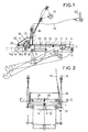
- La figure 1 représente, une vue de côté de l'attelage montrant le fourreau mobile en position verrouillée, avec indication de sa position basse et d'une position intermédiaire en trait mixte.
- La figure 2 représente, une vue de l'arrière de l'attelage, montrant le fourreau mobile en position verrouillée, avec indication de sa position basse en trait mixte.
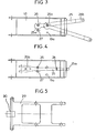
- La figure 3 représente, une vue de dessus du fourreau mobile équipé d'une barre oscillante fixée par l'intermédiaire du crochet de remorquage.
- La figure 4 représente, une vue de dessus du fourreau mobile équipé d'une barre oscillante montée en position crochet.
- La figure 5 représente, une vue de dessus d'un fourreau d'épaisseur réduite équipé d'un crochet de remorquage.
- FIG. 1 represents a side view of the coupling showing the movable sheath in the locked position, with indication of its low position and of an intermediate position in phantom.
- FIG. 2 represents a view of the rear of the coupling, showing the movable sheath in the locked position, with indication of its low position in phantom.
- FIG. 3 represents a top view of the movable sheath equipped with an oscillating bar fixed by means of the towing hook.
- FIG. 4 represents a top view of the movable sheath fitted with an oscillating bar mounted in the hook position.
- FIG. 5 represents a top view of a sheath of reduced thickness equipped with a tow hook.
Les figures représentent un attelage à fourreau mobile constitué principalement d'une partie supérieure 1, montée à l'extrémité arrière 2 du châssis d'un tracteur sous laquelle sont fixées des butées élastiques 3 et 4 et des oreilles 5 et 6 par rapport auxquelles sont articulées, par l'intermédiaire d'axes 7 et 8, les biellettes avant 9 et arrière 10, de longueur différente, supportant, par l'intermédiaire de manetons 11 et 12 le fourreau mobile 13, à l'intérieur duquel est monté une barre de remorquage 14.The figures represent a movable sleeve hitch consisting mainly of an
La manoeuvre du fourreau mobile s'effectue par l'intermédiaire du dispositif de relevage 15 du tracteur, de tiges télescopiques, de longueur réglable, 16 et de manetons 17.The movable sheath is maneuvered by means of the
Le verrouillage du fourreau mobile 13 contre la partie supérieure 1 de l'attelage, avec déformation des butées élastiques 3 et 4, est obtenu par l'intermédiaire de crochets escamotables 18, rappelés en position verrouillée par un ressort 19, dont le bec est muni d'une rampe 18a permettant l'effacement sous l'action des manetons 17.The locking of the
Le déverrouillage du fourreau mobile 13 s'effectue, par compression préalable des butées élastiques 3 et 4, par l'intermédiaire du relevage 15 et des tiges télescopiques 16, puis basculement des crochets 18 sous l'action du câble 19 et du levier 20. Comme on le voit sur la figure 2 les deux crochets escamotables 18 sont reliés entre eux par une traverse 21 sur laquelle est fixée l'une des extrémités du ressort de rappel 19. Ces mécanismes sont protégés par un carter 22. Une traverse 23, située à l'extrémité arrière de la partie supérieure de l'attelage, située juste au dessus de l'ouverture 14a du crochet de remorquage 14,interdit la sortie du dit crochet, de l'anneau de remorquage 24.The
En examinant la figure 3, on remarque que la barre oscillante 25 est retenue à l'intérieur du fourreau mobile 13 par l'intermédiaire du crochet 25a d'un axe amovible 26 et d'un axe fixe formant butée 27. L'axe amovible 26 peut occuper une seconde position 26à, plus rapprochée de l'ouverture du fourreau mobile 13 ; ce qui permet d'obtenir deux amplitudes de débattement différentes. D'autres positions, permettant d'autres débattements, peuvent être envisagées.By examining FIG. 3, it can be seen that the oscillating
La figure 4 montre le fourreau mobile 13 équipé de la même barre oscillante 25 que celle représentée à la figure 3,mais montée en position crochet. Dans ce cas, la chape 25 b est introduite à l'intérieur du fourreau mobile 13 et la barre oscillante est immobilisée longitudinalement par un axe amovible 28 et latéralement par l'axe amovible 26 et l'axe fixe forment butée 27. En position barre oscillante l'axe amovible 28 est mis en position de stockage dans un orifice 13a disposé latéralement dans une zone non balayée par la barre oscillante.Figure 4 shows the
En examinant la figure 5 on remarque que, dans son mode de réalisation simplifié le fourreau mobile 29 est réduit d'épaisseur et que le dispositif d'accrochage 30, dont il est équipé, est fixé sur sa partie arrière.By examining Figure 5 we notice that, in its embodiment simplified tion the
Comme on le voit en se reportant aux figures 1 et 2 :
- En position basse, le fourreau mobile 13 et les biellettes avant 9 sont désalignés et forment un angleo(, dont le sommet est dirigé vers le haut, de façon à obtenir un arc-boutement, sans recul du fourreau mobile 13,lors d'une éventuelle sollicitation vers l'avant du tracteur. Ce désalignement est limité par le débattement réglable des tiges télescopiques 16.
- In the low position, the
movable sheath 13 and thefront links 9 are misaligned and form an angleo (, the apex of which is directed upward, so as to obtain a bracing, without recoil of themovable sheath 13, during a possible forward bias of the tractor This misalignment is limited by the adjustable travel of thetelescopic rods 16.
Lors d'une sollicitation du fourreau mobile 13 vers l'arrière du tracteur, il se produit une légère rotation, vers l'arrière, des biellettes arrière 10, jusqu'à obtention de l'alignement des biellettes avant 9 avec le fourreau mobile 13. L'angle α n'est que très légèrement inférieur à 180°, afin de réduire au minimum l'amplitude du débattement correspondant, tout en assurant la butée longitudinale par arc-boutement du fourreau mobile 13.When the moving
Au début de la remontée du fourreau mobile 13, sous l'action du relevage 15 et des tiges télescopiques 16, l'angleo(devient supérieur à 180°, ce qui élimine l'arc-boutement et permet aux biellettes avant et arrière d'assurer leur fonction.At the beginning of the ascent of the
En position verrouillée, le fourreau mobile est plaqué contre les butées élastiques 3 et 4 sous l'action du crochet de verrouillage 18. Lors d'une sollicitation horizontale,les composantes horizontales et verticales contribuent, par l'intermédiaire des biellettes, à plaquer le fourreau mobile 13 contre les butées élastiques 3 et 4. Cet effet est contrôlée par une légère inclinaison, vers le bas, des biellettes avant 9.In the locked position, the movable sheath is pressed against the
L'élasticité des butées élastiques 3 et 4 est définie de telle sorte que le déverrouillage ne puissse s'effectuer que sous l'action des tiges télescopiques de relevage et non sous l'action des composantes des efforts appliqués.The elasticity of the
Comme on le voit dans cet exemple l'utilisation de jeux de biellettes 9 et 10, de longueur différente, permet de faire suivre au fourreau mobile 13 ou 29, une trajectoire prédéterminée, combinant une rotation à une translation.As can be seen in this example, the use of sets of
Claims (8)
Priority Applications (1)
| Application Number | Priority Date | Filing Date | Title |
|---|---|---|---|
| AT85402200T ATE60549T1 (en) | 1984-11-16 | 1985-11-14 | MOVABLE TRAILER HITCH. |
Applications Claiming Priority (2)
| Application Number | Priority Date | Filing Date | Title |
|---|---|---|---|
| FR8417508 | 1984-11-16 | ||
| FR8417508A FR2573360B1 (en) | 1984-11-16 | 1984-11-16 | MOBILE SLEEVE HITCH |
Publications (2)
| Publication Number | Publication Date |
|---|---|
| EP0184489A1 true EP0184489A1 (en) | 1986-06-11 |
| EP0184489B1 EP0184489B1 (en) | 1991-01-30 |
Family
ID=9309667
Family Applications (1)
| Application Number | Title | Priority Date | Filing Date |
|---|---|---|---|
| EP85402200A Expired - Lifetime EP0184489B1 (en) | 1984-11-16 | 1985-11-14 | Pick-up draw-bar hitch |
Country Status (5)
| Country | Link |
|---|---|
| EP (1) | EP0184489B1 (en) |
| AT (1) | ATE60549T1 (en) |
| DE (2) | DE184489T1 (en) |
| ES (1) | ES290504Y (en) |
| FR (1) | FR2573360B1 (en) |
Cited By (10)
| Publication number | Priority date | Publication date | Assignee | Title |
|---|---|---|---|---|
| FR2602721A1 (en) * | 1986-08-14 | 1988-02-19 | Lemoine Mecano Soudure | DEVICE FOR FIXING REVERSIBLE OSCILLATING BARS IN A MOBILE DOOR HITCH |
| EP0346885A1 (en) * | 1988-06-16 | 1989-12-20 | Roman Johann Sauermann | Apparatus for attaching a trailer to a vehicle |
| DE4201830A1 (en) * | 1992-01-24 | 1993-07-29 | Walterscheid Gmbh Jean | Trailer attachment frame for farm tractor - uses spiral cable to raise and lower frame |
| US5240272A (en) * | 1991-09-17 | 1993-08-31 | Deere & Company | Vehicle hitch assembly |
| EP0561192A1 (en) * | 1992-03-16 | 1993-09-22 | GKN Walterscheid GmbH | Traction device with an opening security |
| DE4238584A1 (en) * | 1992-11-16 | 1994-05-19 | Walterscheid Gmbh Gkn | Lock for trailer coupling linkage on tractor - uses positioning cable connected to position indicator visible to driver and has safety lever positioned between both |
| EP1099575A1 (en) * | 1999-11-09 | 2001-05-16 | Hans Sauermann | Coupling device for an automotive vehicle |
| EP1437241A1 (en) * | 2002-12-20 | 2004-07-14 | Josef Scharmüller | Pick-up-hitch |
| EP1876040A1 (en) * | 2006-07-04 | 2008-01-09 | CBM S.p.A. | Tractor hitch for trailer |
| CN108909854A (en) * | 2018-08-08 | 2018-11-30 | 启东大同电机有限公司 | Heavy semi-automatic hitcher type electrically propelled traction vehicle |
Citations (6)
| Publication number | Priority date | Publication date | Assignee | Title |
|---|---|---|---|---|
| GB1030437A (en) * | 1963-05-23 | 1966-05-25 | Inst Landmaschnen Und Traktore | Improvements in or relating to traction arrangements for the attachment of trailers,implements or the like to tractors |
| FR1552483A (en) * | 1967-01-26 | 1969-01-03 | ||
| US3863955A (en) * | 1970-08-26 | 1975-02-04 | Deere & Co | Pick-up-type drawbar assembly |
| GB1470941A (en) * | 1975-01-14 | 1977-04-21 | Int Harvester Co | Industrial and agricultural tractors |
| GB2042316A (en) * | 1979-02-23 | 1980-09-24 | Kaitanen P | Tractor hitches |
| US4542913A (en) * | 1984-07-26 | 1985-09-24 | Deere & Company | Pick-up type drawbar assembly |
Family Cites Families (1)
| Publication number | Priority date | Publication date | Assignee | Title |
|---|---|---|---|---|
| SE312730B (en) * | 1968-06-26 | 1969-07-21 | N Sjoedin |
-
1984
- 1984-11-16 FR FR8417508A patent/FR2573360B1/en not_active Expired
-
1985
- 1985-11-14 DE DE198585402200T patent/DE184489T1/en active Pending
- 1985-11-14 EP EP85402200A patent/EP0184489B1/en not_active Expired - Lifetime
- 1985-11-14 AT AT85402200T patent/ATE60549T1/en not_active IP Right Cessation
- 1985-11-14 DE DE8585402200T patent/DE3581607D1/en not_active Expired - Fee Related
- 1985-11-14 ES ES1985290504U patent/ES290504Y/en not_active Expired
Patent Citations (6)
| Publication number | Priority date | Publication date | Assignee | Title |
|---|---|---|---|---|
| GB1030437A (en) * | 1963-05-23 | 1966-05-25 | Inst Landmaschnen Und Traktore | Improvements in or relating to traction arrangements for the attachment of trailers,implements or the like to tractors |
| FR1552483A (en) * | 1967-01-26 | 1969-01-03 | ||
| US3863955A (en) * | 1970-08-26 | 1975-02-04 | Deere & Co | Pick-up-type drawbar assembly |
| GB1470941A (en) * | 1975-01-14 | 1977-04-21 | Int Harvester Co | Industrial and agricultural tractors |
| GB2042316A (en) * | 1979-02-23 | 1980-09-24 | Kaitanen P | Tractor hitches |
| US4542913A (en) * | 1984-07-26 | 1985-09-24 | Deere & Company | Pick-up type drawbar assembly |
Cited By (12)
| Publication number | Priority date | Publication date | Assignee | Title |
|---|---|---|---|---|
| FR2602721A1 (en) * | 1986-08-14 | 1988-02-19 | Lemoine Mecano Soudure | DEVICE FOR FIXING REVERSIBLE OSCILLATING BARS IN A MOBILE DOOR HITCH |
| EP0256951A1 (en) * | 1986-08-14 | 1988-02-24 | Sodisene Fabrication Sa | Connecting device for reversible swinging bars in a pick-up drawbar hitch |
| EP0346885A1 (en) * | 1988-06-16 | 1989-12-20 | Roman Johann Sauermann | Apparatus for attaching a trailer to a vehicle |
| US5240272A (en) * | 1991-09-17 | 1993-08-31 | Deere & Company | Vehicle hitch assembly |
| DE4201830A1 (en) * | 1992-01-24 | 1993-07-29 | Walterscheid Gmbh Jean | Trailer attachment frame for farm tractor - uses spiral cable to raise and lower frame |
| EP0561192A1 (en) * | 1992-03-16 | 1993-09-22 | GKN Walterscheid GmbH | Traction device with an opening security |
| DE4208343A1 (en) * | 1992-03-16 | 1993-09-23 | Walterscheid Gmbh Jean | TOWING DEVICE WITH OPENING LOCK |
| DE4238584A1 (en) * | 1992-11-16 | 1994-05-19 | Walterscheid Gmbh Gkn | Lock for trailer coupling linkage on tractor - uses positioning cable connected to position indicator visible to driver and has safety lever positioned between both |
| EP1099575A1 (en) * | 1999-11-09 | 2001-05-16 | Hans Sauermann | Coupling device for an automotive vehicle |
| EP1437241A1 (en) * | 2002-12-20 | 2004-07-14 | Josef Scharmüller | Pick-up-hitch |
| EP1876040A1 (en) * | 2006-07-04 | 2008-01-09 | CBM S.p.A. | Tractor hitch for trailer |
| CN108909854A (en) * | 2018-08-08 | 2018-11-30 | 启东大同电机有限公司 | Heavy semi-automatic hitcher type electrically propelled traction vehicle |
Also Published As
| Publication number | Publication date |
|---|---|
| ATE60549T1 (en) | 1991-02-15 |
| FR2573360B1 (en) | 1987-01-09 |
| DE184489T1 (en) | 1986-11-06 |
| EP0184489B1 (en) | 1991-01-30 |
| ES290504U (en) | 1986-03-16 |
| DE3581607D1 (en) | 1991-03-07 |
| ES290504Y (en) | 1986-10-16 |
| FR2573360A1 (en) | 1986-05-23 |
Similar Documents
| Publication | Publication Date | Title |
|---|---|---|
| EP2897450B1 (en) | Method and apparatus for coupling an agricultur tool to a three point hitch of an agricultur tractor | |
| US5336037A (en) | Tow vehicle for manuevering of vehicles | |
| FR2629979A1 (en) | THREE-POINT HITCHING DEVICE, PARTICULARLY FOR AGRICULTURAL MACHINES | |
| EP0184489A1 (en) | Pick-up draw-bar hitch | |
| EP0511922B1 (en) | Mowing machine with pivoting hitch structure | |
| EP0515294B1 (en) | Swan-neck type separable articulated connection between a load carrying tractor and a semi-trailer for heavy vehicles | |
| FR2641234A1 (en) | Device for connecting a trailer to a tractor | |
| EP0474520B1 (en) | Three-point hitch of a tractor | |
| EP0245570A1 (en) | Hitch for a caravan or trailer | |
| FR1465530A (en) | Coupling device, in particular for the three-point coupling of tillage implements to tractors | |
| FR2485461A1 (en) | VERSATILE SELF-PROPELLED AGRICULTURAL VEHICLE WITH MOBILE DRIVER CAB | |
| EP3900533B1 (en) | Agricultural spray towed by a farm vehicle by means of a coupling system | |
| GB2064290A (en) | Automatic lifting device for an agricultural device, in particular a mower | |
| FR2703955A1 (en) | Improvement to the hitching system between a tractor and an implement of the semi-mounted trailer sort, for example | |
| FR2729816A1 (en) | Towing device for agricultural tractor | |
| FR3042094A1 (en) | METHOD AND DEVICE FOR HITCHING AN AGRICULTURAL TOOL ON A LIFT SYSTEM THREE POINTS OF AN AGRICULTURAL TRACTOR | |
| FR2663812A3 (en) | Agricultural implement comprising a hitching beam which can be brought into a position in which it can pivot with respect to the implement | |
| CA1173472A (en) | Hitch system | |
| FR2633567A1 (en) | DEVICE FOR HANDLING A LOAD CARRIED BY A VEHICLE | |
| FI72167C (en) | Loading apparatus. | |
| FR2652705A1 (en) | Improvement to the system for hitching up on a tractor a trailer with a central axle, and in particular a rear-loading agricultural trailer | |
| BE548436A (en) | ||
| FR2652706A1 (en) | Device for supporting a control box for a machine hitched up to a tractor | |
| CH95449A (en) | Automatic coupling device for vehicles running on rails. | |
| FR2575027A1 (en) | Coupling device for a front loader of a tractor |
Legal Events
| Date | Code | Title | Description |
|---|---|---|---|
| PUAI | Public reference made under article 153(3) epc to a published international application that has entered the european phase |
Free format text: ORIGINAL CODE: 0009012 |
|
| AK | Designated contracting states |
Kind code of ref document: A1 Designated state(s): AT BE DE FR GB IT NL SE |
|
| 17P | Request for examination filed |
Effective date: 19860515 |
|
| ITCL | It: translation for ep claims filed |
Representative=s name: ORGANIZZAZIONE D'AGOSTINI |
|
| TCAT | At: translation of patent claims filed | ||
| TCNL | Nl: translation of patent claims filed | ||
| DET | De: translation of patent claims | ||
| 17Q | First examination report despatched |
Effective date: 19870318 |
|
| GRAA | (expected) grant |
Free format text: ORIGINAL CODE: 0009210 |
|
| AK | Designated contracting states |
Kind code of ref document: B1 Designated state(s): AT BE DE FR GB IT NL SE |
|
| PG25 | Lapsed in a contracting state [announced via postgrant information from national office to epo] |
Ref country code: IT Free format text: LAPSE BECAUSE OF FAILURE TO SUBMIT A TRANSLATION OF THE DESCRIPTION OR TO PAY THE FEE WITHIN THE PRESCRIBED TIME-LIMIT;WARNING: LAPSES OF ITALIAN PATENTS WITH EFFECTIVE DATE BEFORE 2007 MAY HAVE OCCURRED AT ANY TIME BEFORE 2007. THE CORRECT EFFECTIVE DATE MAY BE DIFFERENT FROM THE ONE RECORDED. Effective date: 19910130 Ref country code: AT Effective date: 19910130 Ref country code: NL Effective date: 19910130 Ref country code: SE Effective date: 19910130 |
|
| REF | Corresponds to: |
Ref document number: 60549 Country of ref document: AT Date of ref document: 19910215 Kind code of ref document: T |
|
| REF | Corresponds to: |
Ref document number: 3581607 Country of ref document: DE Date of ref document: 19910307 |
|
| GBT | Gb: translation of ep patent filed (gb section 77(6)(a)/1977) | ||
| NLV1 | Nl: lapsed or annulled due to failure to fulfill the requirements of art. 29p and 29m of the patents act | ||
| PLBI | Opposition filed |
Free format text: ORIGINAL CODE: 0009260 |
|
| PG25 | Lapsed in a contracting state [announced via postgrant information from national office to epo] |
Ref country code: BE Effective date: 19911130 |
|
| 26 | Opposition filed |
Opponent name: ROCKINGER SPEZIALFABRIK FUER ANHAENGERKUPPLUNGEN G Effective date: 19911030 |
|
| BERE | Be: lapsed |
Owner name: S.A. ATTELAGES LEMOINE LA MECANO SOUDURE REMOISE Effective date: 19911130 |
|
| PLBN | Opposition rejected |
Free format text: ORIGINAL CODE: 0009273 |
|
| STAA | Information on the status of an ep patent application or granted ep patent |
Free format text: STATUS: OPPOSITION REJECTED |
|
| 27O | Opposition rejected |
Effective date: 19930325 |
|
| REG | Reference to a national code |
Ref country code: FR Ref legal event code: TP |
|
| REG | Reference to a national code |
Ref country code: FR Ref legal event code: TP |
|
| REG | Reference to a national code |
Ref country code: FR Ref legal event code: TP |
|
| REG | Reference to a national code |
Ref country code: FR Ref legal event code: TP |
|
| REG | Reference to a national code |
Ref country code: GB Ref legal event code: 732E |
|
| PGFP | Annual fee paid to national office [announced via postgrant information from national office to epo] |
Ref country code: GB Payment date: 19980918 Year of fee payment: 14 |
|
| PGFP | Annual fee paid to national office [announced via postgrant information from national office to epo] |
Ref country code: FR Payment date: 19981116 Year of fee payment: 14 |
|
| PGFP | Annual fee paid to national office [announced via postgrant information from national office to epo] |
Ref country code: DE Payment date: 19990128 Year of fee payment: 14 |
|
| PG25 | Lapsed in a contracting state [announced via postgrant information from national office to epo] |
Ref country code: GB Free format text: LAPSE BECAUSE OF NON-PAYMENT OF DUE FEES Effective date: 19991114 |
|
| GBPC | Gb: european patent ceased through non-payment of renewal fee |
Effective date: 19991114 |
|
| PG25 | Lapsed in a contracting state [announced via postgrant information from national office to epo] |
Ref country code: FR Free format text: LAPSE BECAUSE OF NON-PAYMENT OF DUE FEES Effective date: 20000731 |
|
| PG25 | Lapsed in a contracting state [announced via postgrant information from national office to epo] |
Ref country code: DE Free format text: LAPSE BECAUSE OF NON-PAYMENT OF DUE FEES Effective date: 20000901 |
|
| REG | Reference to a national code |
Ref country code: FR Ref legal event code: ST |