EP0183511A1 - Zylinderschloss mit exzentrisch angeordnetem Schlüssel - Google Patents
Zylinderschloss mit exzentrisch angeordnetem Schlüssel Download PDFInfo
- Publication number
- EP0183511A1 EP0183511A1 EP85308551A EP85308551A EP0183511A1 EP 0183511 A1 EP0183511 A1 EP 0183511A1 EP 85308551 A EP85308551 A EP 85308551A EP 85308551 A EP85308551 A EP 85308551A EP 0183511 A1 EP0183511 A1 EP 0183511A1
- Authority
- EP
- European Patent Office
- Prior art keywords
- key
- lock
- groove
- lug
- housing
- Prior art date
- Legal status (The legal status is an assumption and is not a legal conclusion. Google has not performed a legal analysis and makes no representation as to the accuracy of the status listed.)
- Granted
Links
Images


Classifications
-
- E—FIXED CONSTRUCTIONS
- E05—LOCKS; KEYS; WINDOW OR DOOR FITTINGS; SAFES
- E05B—LOCKS; ACCESSORIES THEREFOR; HANDCUFFS
- E05B21/00—Locks with lamelliform tumblers which are not set by the insertion of the key and in which the tumblers do not follow the movement of the bolt e.g. Chubb-locks
- E05B21/06—Cylinder locks, e.g. protector locks
- E05B21/066—Cylinder locks, e.g. protector locks of the rotary-disc tumbler type
-
- Y—GENERAL TAGGING OF NEW TECHNOLOGICAL DEVELOPMENTS; GENERAL TAGGING OF CROSS-SECTIONAL TECHNOLOGIES SPANNING OVER SEVERAL SECTIONS OF THE IPC; TECHNICAL SUBJECTS COVERED BY FORMER USPC CROSS-REFERENCE ART COLLECTIONS [XRACs] AND DIGESTS
- Y10—TECHNICAL SUBJECTS COVERED BY FORMER USPC
- Y10T—TECHNICAL SUBJECTS COVERED BY FORMER US CLASSIFICATION
- Y10T70/00—Locks
- Y10T70/70—Operating mechanism
- Y10T70/7441—Key
- Y10T70/7486—Single key
- Y10T70/7508—Tumbler type
- Y10T70/7559—Cylinder type
- Y10T70/7588—Rotary plug
- Y10T70/7627—Rotary or swinging tumblers
- Y10T70/7633—Transverse of plug
-
- Y—GENERAL TAGGING OF NEW TECHNOLOGICAL DEVELOPMENTS; GENERAL TAGGING OF CROSS-SECTIONAL TECHNOLOGIES SPANNING OVER SEVERAL SECTIONS OF THE IPC; TECHNICAL SUBJECTS COVERED BY FORMER USPC CROSS-REFERENCE ART COLLECTIONS [XRACs] AND DIGESTS
- Y10—TECHNICAL SUBJECTS COVERED BY FORMER USPC
- Y10T—TECHNICAL SUBJECTS COVERED BY FORMER US CLASSIFICATION
- Y10T70/00—Locks
- Y10T70/70—Operating mechanism
- Y10T70/7441—Key
- Y10T70/778—Operating elements
- Y10T70/7791—Keys
- Y10T70/7842—Single shank or stem
- Y10T70/787—Irregular nonplanar or undulated
-
- Y—GENERAL TAGGING OF NEW TECHNOLOGICAL DEVELOPMENTS; GENERAL TAGGING OF CROSS-SECTIONAL TECHNOLOGIES SPANNING OVER SEVERAL SECTIONS OF THE IPC; TECHNICAL SUBJECTS COVERED BY FORMER USPC CROSS-REFERENCE ART COLLECTIONS [XRACs] AND DIGESTS
- Y10—TECHNICAL SUBJECTS COVERED BY FORMER USPC
- Y10T—TECHNICAL SUBJECTS COVERED BY FORMER US CLASSIFICATION
- Y10T70/00—Locks
- Y10T70/70—Operating mechanism
- Y10T70/7441—Key
- Y10T70/778—Operating elements
- Y10T70/7791—Keys
- Y10T70/7881—Bitting
Definitions
- THIS INVENTION relates to tumbler locks and keys therefor, and particularly relates to a two stage tumbler lock and a related key.
- the present invention relates to improvements in both the key and the lock of US Patent No. 4407147.
- Another object of the present invention is to provide an improved lock, and an improved lock and key assembly.
- a peripheral key for a tumbler lock comprising on elongated body member having curved portions for peripheral contact with curved portions of the lock, said elongated body including a handle portion and an operating portion connected together by a dog leg or stepped portion, said operating portion having an outer end remote from said dog leg and an inner end terminating at said dog leg, said operating portion having concentric inner and outer curved faces, said inner face having a longitudinally extending groove formed therein having an open end at the outer end of said operating portion for entry of a sentry lug on the lock and passage of said lug, relatively speaking, along said groove, said groove being defined in part by two side walls and a bottom wall, said inner curved face being formed, at the end of the groove closest the dog leg, with a transverse circumferentially extending arcuate groove communicating with the just mentioned end said luq passage groove, said transverse groove having a blind end located at the inner end of said log passage groove and an open end remote therefrom to permit escape of the sentry
- the invention provides a lock having a housing and plural discs releasably locked against movement relative to the housing by a locking member, rotary plug means within said housing supporting said plural discs, said rotary plug means and discs at least in part defining with the interior of said housing an annular space to receive a peripheral key, a curved pusher plate in said space freely movable relative to said key, means interconnecting said pusher plate with said rotary plug means to permit limited movement only of said pusher plate relative to said plug means, thereby to permit said key to move said pusher plate a limited extent relative to said rotary plug means.
- the invention provides a lock having a housing and plural discs releasably locked against movement relative to the housing by a locking member, rotary plug means within said housing supporting said plural discs, said rotary plug means and discs at least in part defining with the interior of said housing an annular space, a peripheral key to be inserted into said space, said plug means having a radially outwardly projecting lug, said key having curved inner and outer faces, said inner face having a longitudinally extending groove to accept said lug to permit said key to be inserted into said annular space, said longitudinal groove having at one end a laterally extending groove of a size to pass said lug when the lug reaches the end of said longitudinal groove to prohibit turning of said key until of said lug is aligned with the lateral groove.
- US Patent No. 4407147 is designed for peripheral rather than axial insertion and usage.
- the key of the present invention is similarly designed, but it differs from the key of US Patent No. 4407147 in several important respects.
- the latter has a long keyway which dead-ends inboard, and slidably receives a longitudinally extending keying lug on an anti-pick pusher plate.
- the pusher plate in the preferred form of the invention of US Patent No. 4407147 is cut away exteriorly to provide a wide groove to slidably receive the key.
- the key and the pusher plate have an interfitting relationship, so that the key and plate move in unison, and the key has a driving relation to the plate circumferentially.
- One of the functions performed by the keying lug of the pusher plate of the construction of US Patent No. 4407147 is to act as a sentry to block the entryway of the lock to a key not having a matching longitudinal groove.
- the key and the pusher plate are constructed so that they no longer need have the above described interfitting relationship.
- the sentry function previously performed by the pusher plate, is now performed by a lug which is provided on an internal plug in the lock.
- the key of the present invention has a lug passage slot which not only receives the sentry lug, but the slot is L-shaped and opens up laterally so that, after the key is fully inserted, the key can be turned circumferentially to free itself from the lug to enable it to perform its intended functions.
- the pusher plate In order to establish alignment of the longitudinal groove of the key with the keying lug on the pusher plate, at the time of insertion of the key, not only was the pusher plate provided with a camming surface, but the end of the key was also provided with a camming surface to facilitate camming of the two into proper circumferential alignment.
- the circumferential movement of the pusher plate is limited by providing a lug on the plate which is accommodated within a slot on the front interior plug, so that. even when the key is removed the pusher plate has only a limited degree of movement relative to the pluq.
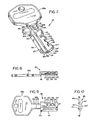
- Figures I and 2 show that a lock embodying the invention comprises a cylindrical housing 21 having an outer flange 23 at its front end.
- the lock is designed to fit through a non-circular hole provided in a mounting plate (not shown), with the flange abutting the plate.
- the housing has flats 24 ( Figure 5) to fit the contour of the hole to non-rotatably mount the housing in place.
- the exterior surface of the rear portion of the housing may be threaded (not shown) so that a nut (not shown), with or without a lock washer, can be used to clamp the housing to the mounting plate.
- the plate can be the front wall of a key containing safe, or the lock can be mounted in any desired manner.
- a rear plug 25 (Figure 2) turnably fitting within the housing and retained in place by a snap ring 26.
- the plug has a rearwardly projecting stub shaft 27, having flats 28 to non-rotatably receive a locking member 29.
- a stop plate 30 Interposed between the locking member 29 and the plug is a stop plate 30 which is non-rotatably received by the shaft 27.
- a nut 31 clamps both the locking member and the stop plate onto the shaft.
- the locking member 29 coacts with an inner surface of a lock receiving structure (not shown), to provide access to structure when the locking member is in its unlocked position, or to preclude access when the locking member is in its locking position.
- stop plate or member 30 The function of the stop plate or member 30 is explained in US Patent No. 4407147 so the explanation here will be brief. Its purpose is to limit the amount of circumferential movement permitted the interior parts of the lock under the influence of the key. It does this by means of a luq 21a ( Figure 2) on the housing 2) projecting into a notch formed in the periphery of the stop plate.
- the plug 25 has a forwardly projecting shaft 35 which is of square cross section and is non-rotatably received at its rear end by plug 25 and its forward end by a front plug 36, which turnably fits within the housing 21.
- Shaft 35 is non-rotatably received within non-circular holes 39(Fiqure 6) provided in a series of actuating discs 41, while the shaft rotatably extends through circular holes 42 provided in code discs 43.
- a spring 44 (Fiqure 2) urges the stack of discs together.
- tumbler or latch member 45 (Figures 3 and 6), of qenerally rectangular cross section, whose outer edge fitrs in a notch 49 ( Figures 3 and 5).
- the notch has a ramp 51 to be presently referred to again.
- the tumbler slidably fits within notches 55 provided in the plugs 25 and 36 ( Figures, 3, 5, 6, 6A and 6B).
- the tumbler will be cammed inwardly by forced engagement with the ramp 51, upon clockwise movement of the actuating discs 41, but such inward camming movement will be prohibited by the code discs 43, until the code discs have been moved to predetermined clearance positions (as will be presently described).
- the code discs 43 are similar in construction to the code discs of the preferred form of the construction described in US Patent No. 4407147. Suffice it to say that each has a pair of lugs 63 which flank. and in part define, shoulder 62. A key 65 ( Figure 5) is located in position to contact the nearest lugs 63 of the code discs (which action will be alluded to again, later).
- a code notch 67 is formed in the shoulder 62, the notch usually being differently located circumferentially along the associated shoulder on different code discs, depending on the overall code of the lock. Thus typically the code notch of one code disc will be differently disposed than that of an adjacent code disc. That is not mandatory because the overall code sequence might call for the code notch to be similarly located on another coded disc.
- the notch 67 is of a size to receive the tumbler 45, as is evident from Figure 5, but is out of line with the tumbler in the locked condition of the lock. Thus, in the locked condition, the tumbler will rest on or overlie the shoulder 62.
- each of the actuating discs 41 has a pair of lugs 81 defining a deep notch 83 which at all times slidably receives the tumbler 45 ( Figure 5).
- the housing has at its front portion a radially inwardly extending flange 87 in which is formed a circular hole 88, the flange having a notch 89 formed therein to accommodate the key 65, up to an including a dog leg 66 of the key.
- the plug 36 has a portion 90 ( Figures I and 6A) projecting forwardly into the hole 88, but being arcuately cut away at 90a ( Figure 6A) to leave an inset forward face 90b.
- the cutaway is of sufficient depth that when the key is fully inserted, the dog leg 66 can pass circumferentially behind the flange 87. When the dog leg is so positioned, the flange precludes withdrawal of the key until the key is retro-turned to its initial position in register with the notch 89.
- Figures 2 and 5 show a curved sector-like anti-pick pusher plate 93 which is cut away to provide a thin portion 93a underlying the key 65, and overlying and concentric with the inner curved edges 94 of the discs 41 and 43.
- the thicker portion 93b of the pusher plate is slidably and concentrically received between the inner surface of the housing 21 and the edges 94 of the discs.
- the thicker portion 93b is formed with a cam surface 96 ( Figure 6) to be engaged by the trailing corner 65e of an operating portion 64 of the key, as the key is inserted into the lock. This action deflects the pusher plate sideways, should it be in an entrance-barring position, at the time that the key is inserted into the lock. The action also establishes an operating relationship between the operating portion of the key and the pusher plate.
- the key has a handle portion 65a, a shank portion 65b, the dog leg 66, and the operating portion 64.
- the operating portion is formed on its inner curved face with an L-shaped groove or slot, having a longitudinal lug-passage groove 101, and a lateral lug-passage groove 103.
- Groove 101 is defined by sidewalls 105 and 107, a bottom wall 109, and an end wall defined by the inner face 121 of the dog leg 66.
- groove 101 is longitudinally blind at its inner end, except for the lateral exit 103.
- the lateral lug passage groove 103 is defined by a bottom wall 123, the face 121 at one side, and a short wall 125 at its opposite side.
- the lateral lug passage groove stops at the wall 107 and thus is blind at its inner end, except for its communication with the groove 101.
- the bottom wall 123 is of arcuate configuration, being concentric with the axis of the lock, for a reason that will presently appear.
- the L-shaped groove defines a land 127 which is a continuation of the inner curved face 64' of the operating portion 64 of the key. As is evident from Figures 4 and 10, the inner face and the outer face 64" of the operating portion 64 are concentric about the central axis of the lock.
- the shank 65b has a central inner face portion 141 which is concentric with the main axis of the lock, such curved portion being flanked by land portions 143.
- the side edges 145 of the shank portion are parallel to one another and merge into parallel side edges 151 of the dog leg 66. It is evident from the just described construction, that the shank portion, including the vertical portion of the dog leg, is narrower and thus offset from the broader width of the operating portion 64 of the key ( Figure 7).
- the key 65 in its blank form (See Figure 6) is provided with an operating edge 161 which faces circumferentially, and into which cuts are made to provide bits, seven bits 171, 172, 173, 174, 175, 176 and 177 being shown in Figures 7 - 9 by way of example.
- bits 171, 173, 175 and 177 are wider (in an axial direction) than the other bits, all could be made of the same width. However, preferably, they are formed as shown so that the projecting bits will have substantial width for strength purposes.
- the front plug 36 is provided with a sentry lug 20 ( Figures I and 6) which guards the entryway of the lock. It is of a size to slidably receive the lug-passage groove 101 and thus permit insertion of the key into the lock.
- the lug is also of a size, depthwise, to permit the lug, once the key is fully inserted, to pass circumferentially through the lateral lug-passage groove 103 of the key to free the key from the lug and to permit further turning movement of the key.
- the curved operating portion 64 of the key is slidably confined ( Figures I and 3) between the opposed inner curved surface of the housing 21, and the exterior curved surface portions 36a and 25a of the front and rear plugs. This maintains alignment of the key with the axis of the lock, during turning movemement of the key.
- the key 65 is inserted into the lock, with the key pushing the pusher plate aside If it is in the way, until the key is fully inserted, with the sentry lug 201 sliding along the groove 101.
- This position of the parts is shown in Figures 2 and 4.
- the key is now moved or turned clockwise, with the sentry lug 201 sliding in a curved path through the curved lateral groove 103 ( Figure 4) in the key so as to leave the lug behind.
- the key is turned counterclockwise to engage the pusher plate and push it around until it engages the farthest disposed lugs 63 (those of the "O" position code discs).
- the key continues retro-movement of the key causes the entire interior assembly to move around back to a position just prior to that in Figure 5, where the stop lug 21a engages the opposite edge of the notch in the stop plate 30 to stop movement of the shaft 35 and all parts keyed to it (and leave the locking member 29 in its locked position).
- Continued retro-movement of the key by applying a turning force to the "O" position code discs, causes the camming edges 67a of the code discs to cam the tumbler 45 back into the notch 49.
- the key of the present invention is unique in a number of respects.
- One of its unique features is that not only must the key groove match the height and width of lug 201, but also the depth of the luq. If the lug is too deep, while the lug can pass along the longitudinal leg of the key groove, as the key is inserted, it cannot pass laterally to free the key from the luq.
- the lug and groove relationship has a size requirement in three dimensions, the x, y and z axes.
- the above feature of the key means that the luq and qroove relationship between the groove on the key and the lug 201 assure that the key cannot be turned before the key is fully inserted. Turning before that time would cause a hang up of the key bits on the front flange of the lock housing. A similar hang up could occur if the key were rotated while being removed. Thus, the lug keeps the key from turning until the proper time, a function added to that of the sentry purposes of the lug.
- a unique relationship of the lock and key is that although the key does not have a keyed interfitted relation with the pusher plate, it nevertheless is constrained against unacceptable lateral play by its concentric surface interfit between the interior curved surface of the housing 21, on the one hand, and the exterior curved surfaces of inwardly adjacent portions of the plugs 25 and 36, on the other.
Priority Applications (1)
| Application Number | Priority Date | Filing Date | Title |
|---|---|---|---|
| AT85308551T ATE46009T1 (de) | 1984-11-26 | 1985-11-25 | Zylinderschloss mit exzentrisch angeordnetem schluessel. |
Applications Claiming Priority (2)
| Application Number | Priority Date | Filing Date | Title |
|---|---|---|---|
| US673933 | 1984-11-26 | ||
| US06/673,933 US4578969A (en) | 1984-11-26 | 1984-11-26 | Tumbler lock having peripheral key |
Publications (2)
| Publication Number | Publication Date |
|---|---|
| EP0183511A1 true EP0183511A1 (de) | 1986-06-04 |
| EP0183511B1 EP0183511B1 (de) | 1989-08-30 |
Family
ID=24704678
Family Applications (1)
| Application Number | Title | Priority Date | Filing Date |
|---|---|---|---|
| EP85308551A Expired EP0183511B1 (de) | 1984-11-26 | 1985-11-25 | Zylinderschloss mit exzentrisch angeordnetem Schlüssel |
Country Status (5)
| Country | Link |
|---|---|
| US (1) | US4578969A (de) |
| EP (1) | EP0183511B1 (de) |
| AT (1) | ATE46009T1 (de) |
| CA (1) | CA1251341A (de) |
| DE (1) | DE3572707D1 (de) |
Families Citing this family (28)
| Publication number | Priority date | Publication date | Assignee | Title |
|---|---|---|---|---|
| US5136869A (en) * | 1991-03-29 | 1992-08-11 | Best Lock Corporation | High security key and cylinder lock assembly |
| US5272895A (en) * | 1991-03-29 | 1993-12-28 | Best Lock Corporation | High security key and cylinder lock assembly |
| US5176015A (en) * | 1991-04-10 | 1993-01-05 | Sussina Stan J | Restricted key system |
| US6718806B2 (en) | 2000-01-25 | 2004-04-13 | Videx, Inc. | Electronic locking system with emergency exit feature |
| US6615625B2 (en) | 2000-01-25 | 2003-09-09 | Videx, Inc. | Electronic locking system |
| US6474122B2 (en) | 2000-01-25 | 2002-11-05 | Videx, Inc. | Electronic locking system |
| CN100373031C (zh) * | 2005-02-23 | 2008-03-05 | 北京华清九地锁业科技有限公司 | 旋匙线配限位锁 |
| US20070044523A1 (en) * | 2005-08-26 | 2007-03-01 | Videx, Inc. | Lock |
| US20070084260A1 (en) * | 2005-10-13 | 2007-04-19 | Alfredo Muerza | Rotary disc lock and key security system |
| US10070680B2 (en) | 2008-06-13 | 2018-09-11 | Nike, Inc. | Footwear having sensor system |
| JP5925490B2 (ja) | 2008-06-13 | 2016-05-25 | ナイキ イノベイト セー. フェー. | センサシステムを有するフットウェア |
| US9549585B2 (en) | 2008-06-13 | 2017-01-24 | Nike, Inc. | Footwear having sensor system |
| US9002680B2 (en) * | 2008-06-13 | 2015-04-07 | Nike, Inc. | Foot gestures for computer input and interface control |
| US8831407B2 (en) | 2010-11-10 | 2014-09-09 | Nike, Inc. | Systems and methods for time-based athletic activity measurement and display |
| KR101767794B1 (ko) | 2011-02-17 | 2017-08-11 | 나이키 이노베이트 씨.브이. | 위치 맵핑 |
| CN112545101B (zh) | 2011-02-17 | 2022-05-03 | 耐克创新有限合伙公司 | 带传感器系统的鞋 |
| US9381420B2 (en) | 2011-02-17 | 2016-07-05 | Nike, Inc. | Workout user experience |
| CN103476335B (zh) | 2011-02-17 | 2017-06-09 | 耐克创新有限合伙公司 | 具有传感器系统的鞋 |
| US20130213146A1 (en) | 2012-02-22 | 2013-08-22 | Nike, Inc. | Footwear Having Sensor System |
| US11684111B2 (en) | 2012-02-22 | 2023-06-27 | Nike, Inc. | Motorized shoe with gesture control |
| US11071344B2 (en) | 2012-02-22 | 2021-07-27 | Nike, Inc. | Motorized shoe with gesture control |
| US20130213147A1 (en) | 2012-02-22 | 2013-08-22 | Nike, Inc. | Footwear Having Sensor System |
| US9743861B2 (en) | 2013-02-01 | 2017-08-29 | Nike, Inc. | System and method for analyzing athletic activity |
| US10926133B2 (en) | 2013-02-01 | 2021-02-23 | Nike, Inc. | System and method for analyzing athletic activity |
| US11006690B2 (en) | 2013-02-01 | 2021-05-18 | Nike, Inc. | System and method for analyzing athletic activity |
| US9410857B2 (en) | 2013-03-15 | 2016-08-09 | Nike, Inc. | System and method for analyzing athletic activity |
| US20150152666A1 (en) * | 2013-12-04 | 2015-06-04 | Real Lock & Security Co., Ltd. | Lock Core with Different Thicknesses of Lock Plates |
| CN206513136U (zh) * | 2016-12-15 | 2017-09-22 | 厦门美科安防科技有限公司 | 双层无簧角度叶片锁 |
Citations (2)
| Publication number | Priority date | Publication date | Assignee | Title |
|---|---|---|---|---|
| FR2317452A1 (fr) * | 1975-06-25 | 1977-02-04 | Freedman Gerald | Perfectionnements aux verrous de surete |
| US4407147A (en) * | 1980-12-22 | 1983-10-04 | Supra Products, Inc. | Peripheral key tumbler lock |
Family Cites Families (7)
| Publication number | Priority date | Publication date | Assignee | Title |
|---|---|---|---|---|
| US688070A (en) * | 1901-08-19 | 1901-12-03 | Walter G Denn | Lock. |
| US1553639A (en) * | 1924-09-30 | 1925-09-15 | Warren S Sherman | Cover lock |
| US1915897A (en) * | 1933-04-28 | 1933-06-27 | Maxwell C Maxwell | Lock key |
| US2578211A (en) * | 1948-07-16 | 1951-12-11 | Yale & Towne Mfg Co | Side bar cylinder lock |
| US3334501A (en) * | 1965-10-20 | 1967-08-08 | Louis Wolff | Protective device for locks |
| US3821886A (en) * | 1972-03-09 | 1974-07-02 | W Ladewig | Pick-proof locks |
| SU417594A1 (ru) * | 1972-11-27 | 1974-02-28 | С. Н. Клоков , Г. Г. Курилов | Цилиндровый механизм для замка |
-
1984
- 1984-11-26 US US06/673,933 patent/US4578969A/en not_active Expired - Lifetime
- 1984-12-07 CA CA000469621A patent/CA1251341A/en not_active Expired
-
1985
- 1985-11-25 DE DE8585308551T patent/DE3572707D1/de not_active Expired
- 1985-11-25 AT AT85308551T patent/ATE46009T1/de not_active IP Right Cessation
- 1985-11-25 EP EP85308551A patent/EP0183511B1/de not_active Expired
Patent Citations (2)
| Publication number | Priority date | Publication date | Assignee | Title |
|---|---|---|---|---|
| FR2317452A1 (fr) * | 1975-06-25 | 1977-02-04 | Freedman Gerald | Perfectionnements aux verrous de surete |
| US4407147A (en) * | 1980-12-22 | 1983-10-04 | Supra Products, Inc. | Peripheral key tumbler lock |
Also Published As
| Publication number | Publication date |
|---|---|
| US4578969A (en) | 1986-04-01 |
| DE3572707D1 (en) | 1989-10-05 |
| ATE46009T1 (de) | 1989-09-15 |
| CA1251341A (en) | 1989-03-21 |
| EP0183511B1 (de) | 1989-08-30 |
Similar Documents
| Publication | Publication Date | Title |
|---|---|---|
| EP0183511B1 (de) | Zylinderschloss mit exzentrisch angeordnetem Schlüssel | |
| AU2002245512B2 (en) | High security cylinder lock and key | |
| EP0605932B1 (de) | Verriegelungsvorrichtung | |
| US5010753A (en) | Interchangeable core lock | |
| US5615566A (en) | Cylinder lock and key | |
| EP0617184B1 (de) | Zylinderschloss-Schlüssel-Kombination | |
| CA2146307C (en) | Removable core lock with latch alignment and limited latch rotation | |
| US4672827A (en) | Disc tumbler lock with removable plug | |
| US5076081A (en) | Key for interchangable core lock | |
| AU2002245512A1 (en) | High security cylinder lock and key | |
| US5050412A (en) | Flat key cylinder lock with anti-burglar features | |
| PL179490B1 (pl) | Urzadzenie zamykajace z zamkiem bebenkowym i plaskim kluczem PL | |
| US4624119A (en) | Tumbler lock | |
| EP0912810B1 (de) | Verschlusssystem mit schlüsselfangeinrichtung | |
| US4416129A (en) | Cylinder lock with key removable plug | |
| AU2340100A (en) | Removable core cylinder lock | |
| PL186558B1 (pl) | Zespół zamka bębenkowego i klucza, zamek bębenkowy i surowy klucz do zamka bębenkowego | |
| CA2103952C (en) | Key for use with 5-pin and 6-pin door locks | |
| EP0161654B2 (de) | Diebstahlsicheres Zylinderschloss, insbesondere für Systeme mit Haupt- und Nebenschlüsseln | |
| PL181854B1 (pl) | Wkladka bebenkowa z kluczem plaskim PL | |
| US3956912A (en) | Filing cabinet lock having plate tumbler-type plug assembly | |
| CA1088336A (en) | Disposable core for lock cylinder | |
| US5551263A (en) | Lock with dead bolt camming action on 90 degree lock cylinder rotation | |
| CA1090604A (en) | Plugless pin tumbler cylinder | |
| US4432677A (en) | Cutter for cylindrical locks |
Legal Events
| Date | Code | Title | Description |
|---|---|---|---|
| PUAI | Public reference made under article 153(3) epc to a published international application that has entered the european phase |
Free format text: ORIGINAL CODE: 0009012 |
|
| AK | Designated contracting states |
Kind code of ref document: A1 Designated state(s): AT BE CH DE FR GB IT LI LU NL SE |
|
| 17P | Request for examination filed |
Effective date: 19860724 |
|
| 17Q | First examination report despatched |
Effective date: 19880121 |
|
| GRAA | (expected) grant |
Free format text: ORIGINAL CODE: 0009210 |
|
| ITF | It: translation for a ep patent filed |
Owner name: DE DOMINICIS & MAYER S.R.L. |
|
| AK | Designated contracting states |
Kind code of ref document: B1 Designated state(s): AT BE CH DE FR GB IT LI LU NL SE |
|
| PG25 | Lapsed in a contracting state [announced via postgrant information from national office to epo] |
Ref country code: SE Effective date: 19890830 Ref country code: NL Effective date: 19890830 Ref country code: BE Effective date: 19890830 Ref country code: AT Effective date: 19890830 |
|
| REF | Corresponds to: |
Ref document number: 46009 Country of ref document: AT Date of ref document: 19890915 Kind code of ref document: T |
|
| REF | Corresponds to: |
Ref document number: 3572707 Country of ref document: DE Date of ref document: 19891005 |
|
| ET | Fr: translation filed | ||
| PG25 | Lapsed in a contracting state [announced via postgrant information from national office to epo] |
Ref country code: LU Free format text: LAPSE BECAUSE OF NON-PAYMENT OF DUE FEES Effective date: 19891130 Ref country code: LI Free format text: LAPSE BECAUSE OF NON-PAYMENT OF DUE FEES Effective date: 19891130 Ref country code: CH Free format text: LAPSE BECAUSE OF NON-PAYMENT OF DUE FEES Effective date: 19891130 |
|
| REG | Reference to a national code |
Ref country code: CH Ref legal event code: PL |
|
| NLV1 | Nl: lapsed or annulled due to failure to fulfill the requirements of art. 29p and 29m of the patents act | ||
| PLBI | Opposition filed |
Free format text: ORIGINAL CODE: 0009260 |
|
| 26 | Opposition filed |
Opponent name: GECO GMBH SICHERUNGSTECHNIK Effective date: 19900530 |
|
| PGFP | Annual fee paid to national office [announced via postgrant information from national office to epo] |
Ref country code: FR Payment date: 19901012 Year of fee payment: 6 |
|
| PGFP | Annual fee paid to national office [announced via postgrant information from national office to epo] |
Ref country code: DE Payment date: 19901016 Year of fee payment: 6 |
|
| PGFP | Annual fee paid to national office [announced via postgrant information from national office to epo] |
Ref country code: GB Payment date: 19901031 Year of fee payment: 6 |
|
| ITTA | It: last paid annual fee | ||
| PG25 | Lapsed in a contracting state [announced via postgrant information from national office to epo] |
Ref country code: GB Effective date: 19911125 |
|
| RDAG | Patent revoked |
Free format text: ORIGINAL CODE: 0009271 |
|
| STAA | Information on the status of an ep patent application or granted ep patent |
Free format text: STATUS: PATENT REVOKED |
|
| GBPC | Gb: european patent ceased through non-payment of renewal fee | ||
| REG | Reference to a national code |
Ref country code: CH Ref legal event code: PL |
|
| 27W | Patent revoked |
Effective date: 19920421 |
|
| REG | Reference to a national code |
Ref country code: FR Ref legal event code: ST |