EP0183135A1 - Automatischer Schneid- und Wickelapparat für Bahnen, z.B. Film - Google Patents
Automatischer Schneid- und Wickelapparat für Bahnen, z.B. Film Download PDFInfo
- Publication number
- EP0183135A1 EP0183135A1 EP85114435A EP85114435A EP0183135A1 EP 0183135 A1 EP0183135 A1 EP 0183135A1 EP 85114435 A EP85114435 A EP 85114435A EP 85114435 A EP85114435 A EP 85114435A EP 0183135 A1 EP0183135 A1 EP 0183135A1
- Authority
- EP
- European Patent Office
- Prior art keywords
- web
- film
- swingable arm
- charging means
- core
- Prior art date
- Legal status (The legal status is an assumption and is not a legal conclusion. Google has not performed a legal analysis and makes no representation as to the accuracy of the status listed.)
- Granted
Links
Images


Classifications
-
- B—PERFORMING OPERATIONS; TRANSPORTING
- B65—CONVEYING; PACKING; STORING; HANDLING THIN OR FILAMENTARY MATERIAL
- B65H—HANDLING THIN OR FILAMENTARY MATERIAL, e.g. SHEETS, WEBS, CABLES
- B65H19/00—Changing the web roll
- B65H19/10—Changing the web roll in unwinding mechanisms or in connection with unwinding operations
- B65H19/20—Cutting-off the expiring web
-
- B—PERFORMING OPERATIONS; TRANSPORTING
- B65—CONVEYING; PACKING; STORING; HANDLING THIN OR FILAMENTARY MATERIAL
- B65H—HANDLING THIN OR FILAMENTARY MATERIAL, e.g. SHEETS, WEBS, CABLES
- B65H19/00—Changing the web roll
- B65H19/22—Changing the web roll in winding mechanisms or in connection with winding operations
- B65H19/26—Cutting-off the web running to the wound web roll
-
- B—PERFORMING OPERATIONS; TRANSPORTING
- B65—CONVEYING; PACKING; STORING; HANDLING THIN OR FILAMENTARY MATERIAL
- B65H—HANDLING THIN OR FILAMENTARY MATERIAL, e.g. SHEETS, WEBS, CABLES
- B65H19/00—Changing the web roll
- B65H19/22—Changing the web roll in winding mechanisms or in connection with winding operations
- B65H19/28—Attaching the leading end of the web to the replacement web-roll core or spindle
-
- B—PERFORMING OPERATIONS; TRANSPORTING
- B65—CONVEYING; PACKING; STORING; HANDLING THIN OR FILAMENTARY MATERIAL
- B65H—HANDLING THIN OR FILAMENTARY MATERIAL, e.g. SHEETS, WEBS, CABLES
- B65H2301/00—Handling processes for sheets or webs
- B65H2301/40—Type of handling process
- B65H2301/41—Winding, unwinding
- B65H2301/414—Winding
- B65H2301/41419—Starting winding process
- B65H2301/41421—Starting winding process involving electrostatic means
-
- Y—GENERAL TAGGING OF NEW TECHNOLOGICAL DEVELOPMENTS; GENERAL TAGGING OF CROSS-SECTIONAL TECHNOLOGIES SPANNING OVER SEVERAL SECTIONS OF THE IPC; TECHNICAL SUBJECTS COVERED BY FORMER USPC CROSS-REFERENCE ART COLLECTIONS [XRACs] AND DIGESTS
- Y10—TECHNICAL SUBJECTS COVERED BY FORMER USPC
- Y10S—TECHNICAL SUBJECTS COVERED BY FORMER USPC CROSS-REFERENCE ART COLLECTIONS [XRACs] AND DIGESTS
- Y10S242/00—Winding, tensioning, or guiding
- Y10S242/906—Static charger or discharger
Definitions
- the present invention relates to an automatic cutting and winding apparatus for a web-like material such as a film, which automatically cuts a web-like material such as a film and continuously performs rewinding, and which is applicable to a biaxial oriented film manufacturing system, an unoriented film manufacturing system or the like.
- a winding system for a web-like material such as a film (hereinafter called simply "film”) in which a medium for giving an adhesiveness such as an adhesive tape is not used on a core but a film is wrapped directly around a core (hereinafter called “tapeless winding system”) has been being given attention in various fields because damages of films in inner layers of a mill roll caused by unevenness of a core surface due to an adhesive tape or the like are not present and also a work of removing remaining adhesive materials upon reuse of the core is unnecessary, but there still remain problems such that scratches are generated at a cut end of a film, and therefore, development of a more complete system has been strongly desired.
- a turret type automatic cutting and winding apparatus for automatically cutting a web-like material by means of a press roll and a cutter and winding it around a core, which apparatus comprises electrostatic charging means mounted on a swingable arm or arms for giving electrostatic charge on a cut end portion of the web-like material.
- the turret type automatic cutting and winding apparatus is constructed in the above-featured manner, upon cutting a web-like material and rewinding it on a new core, the swingable arm or arms would make swing motion, electrostatic charge is given on a cut end portion of the web-like material by the electrostatic charging means mounted on the swingable arm or arms, thereby the cut end portion of the web-like material is made to adhere to the surface of the new core by an electrostatic attracting force, and simultaneously, winding of the web-like material around the new core is commenced. Therefore, slip would not occur between the surface of the new core and the cut end portion of the web-like material, and so, scratches would not be generated at the cut end portion of the web-like material.
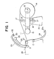
- reference numeral 1 designates a film
- reference numeral 2 designates a new core around which a cut film is to be rewound
- this core 2 is mounted on one arm of a turret 4 so as to be rotationally driven in the direction of arrow A by means of a driving device not shown
- Reference numeral 3 designates a guide roll that is pivotably supported at an end of another arm of the turret 4 angularly apart by 90° from the arm on which the core 2 is mounted.
- Reference numeral 5 also designates a guide roll, which is pivotably supported at a film feed end of a frame 10, and in addition, a swingable arm 7 pivotably supporting at its tip end a wrapping roll 6, which can be revolved in the direction of arrow B so as to traverse a middle portion between the guide roll 5 and the core 2, is pivotably supported at the other end by one end of the frame 10 on the side of winding the film.
- the above-mentioned wrapping roll 6 is adapted to revolve so as to traverse the middle portion between the guide roll 5 and the core 2 as described above and to reach the rear side of the core 2.
- Reference numeral 8 designates a cutter mounted at a tip end of an arm 9 which is likewise pivotably mounted at the other end to an appropriate position of the frame 10.
- This arm 9 is adapted to be made to swing in synchronism with the revolution of the wrapping roll 6 by a driving device not shown and to cut the film 1 with the cutter 8 mounted at its tip end.
- the film 1 is being continuously wound around a core (not shown) mounted at an remote end of the turret 4 on the opposite side to the end where the core 2 is mounted. If a mill roll being wound around that core reaches its full volume, then the wrapping roll 6 advances in the direction of B so as to embrace the core 2 with the film 1, and the state shown in Fig. 8 is attained.
- the cutter 8 is made to descend to cut the film 1 as shown in Fig. 9, then a film end a is forced to enter a gap space b between the core 2 and the wrapping roll 6, and thereby wrapping is finished.
- FIG. 1 to 4 A first preferred embodiment of the present invention is illustrated in Figs. 1 to 4, in which reference numeral 11 designates a film, numerals 12 and 13 designate cores, and these cores 12 and 13 are pivotably supported from the opposite end portions of a turret 16 so as to be rotatable in the direction of arrow A as driven by a driving device not shown, the turret 16 being mounted on a frame 19 so as to be rotatable about its center in the direction of arrow C.
- arms 18 are provided on the opposite sides of the central portion of the turret 16 as projecting therefrom, and at the respective tip end portions of the arms 18 are pivotably supported guide rolls 17, respectively.
- Reference numeral 14 designates a mill roll formed by winding up the film 11 around the core 18.
- a guide roll 27 along a film feed passageway
- swingable arms 26 and 23 which can swing about the same axis D.
- the swingable arm 23 has electrostatic charging means 20 and a cutter 22 mounted at its tip end portion, and a press roll 25 is pivotably mounted at the tip end portion of the swingable arm 26.
- a similar swingable arm 24 having electrostatic charging means 20a mounted at its tip end portion is pivotably mounted on the same frame 28 under the above-described guide roll 27 so as to swing about point E.
- electrode sections of the well-known blast type electrostatic charging devices such as, for example, the heretofore commonly used devices in which ionized air produced by corona discharge between high-voltage electrodes is blasted by a blower or a compressor, are employed. It is to be noted that a power supply section and wirings of the electrostatic charging device are omitted from illustration.
- Fig. 1 shows the state of the apparatus at the time point when the mill roll 14 on the right-side core 12 as viewed in the figure has reached a full amount.
- the wound length of the film 11 is measured by a wound length counter not shown, and when it has reached the full amount, the arm 24 is actuated, and is made to stand by at the position shown in Fig. 2, subsequently the arms 23 and 26 are actuated to cut the film 11 by the cutter 22 and to simultaneously press the film 11 against the new core 13 by means of the press roll 25.
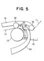
- a cutter 35 is mounted at a tip end of an arm 34 which corresponds to the arm 24 in the first preferred embodiment, further an upper swingable arm 31 is provided only one, a press roll 32 being pivotably supported at the middle of the arm 31, a guide roll 33 also being pivotably supported at the tip end portion of the arm 31, and electrostatic charging means 20 is mounted on the arm 31 close to the press roll 32 on the side of the guide roll 33.
- the construction is identical to the first preferred embodiment.
- the stop position of the cutter 35 can be made as close as possible to the core 13 for the purpose of minimizing the length of the film end portion a.
- the arm 31 is also lowered to the position shown in Fig. 5, to press the film 11 onto the cutter 35 at a high speed by the rolls 32 and 33, and thereby the film 11 can be cut.
- ionized air is blasted from the electrode sections 20 and 20a of the electrostatic charging means onto the cut end portion a of the film 11, thereby the charged cut end portion a of the film 11 is made to adhere to the core 13, and then winding of the film 11 around the core 13 is carried out.
- the arms 31 and 34 are respectively made to ascend and descend, respectively. It is to be noted that either the arm 31 could be made to descend first and subsequently the arm 34 could be made to ascend to cut the film 11 or the arms 31 and 34 could be actuated simultaneously.
- Fig. 6 shows still another preferred embodiment of the present invention. Differences between this preferred embodiment and the above-described embodiment illustrated in Fig. 5 exist in that the single arm.31 in Fig. 5 is modified into two arms 36 and 38, a guide roll 37 is mounted at the tip end of the arm 36, electrostatic charging means 20 is mounted at the tip end of the other arm 38, and a press roll 39 is pivotably supported from the same arm 38 close to the electrostatic charging means on its inner side. With regard to the remainder of the apparatus, the construction is identical to the preferred embodiment shown in Fig. 5.
- the arm 34 could be made to swing prior to the swing motions of the arms 36 and 38, or else, all the arms 34, 36 and 38 could be actuated simultaneously to cut the film 11.
- the press rolls 25, 32 and 39 can be used as a lay-on roll for controlling winding hardness of the mill roll.
- the cut end portion of the film could be made to adhere to the core only by giving electrostatic charge onto the cut end portion.
- the electrostatic charging device can be employed only one (for instance, the electrode section 20 only), or three or more.
- the cut end portion of the film could be wrapped around the core by separately performing electrostatic charging and air-blasting for pressing.
- an electrostatic charging electrode section could be provided at the mount position of the electrode section 20, and an air-blasting nozzle section could be provided at the mount position of the electrode section 20a.
- the film is made to adhere to the core by charging the film, in a tapeless winding system there is no need to embrace the core with the film prior to cutting, hence in the final portion of winding of a mill roll, a film section which comes into contact with the core and is subjected to scratching damage, resulting in loss of a yield, can be eliminated, and so, a yield of a film is greatly improved. It is to be noted that this effect becomes more remarkable as the winding speed of a film becomes faster.
Applications Claiming Priority (2)
| Application Number | Priority Date | Filing Date | Title |
|---|---|---|---|
| JP253090/84 | 1984-11-30 | ||
| JP59253090A JPS61130164A (ja) | 1984-11-30 | 1984-11-30 | フイルム等帯状物の自動切断巻取装置 |
Publications (3)
| Publication Number | Publication Date |
|---|---|
| EP0183135A1 true EP0183135A1 (de) | 1986-06-04 |
| EP0183135B1 EP0183135B1 (de) | 1988-05-18 |
| EP0183135B2 EP0183135B2 (de) | 1991-12-04 |
Family
ID=17246348
Family Applications (1)
| Application Number | Title | Priority Date | Filing Date |
|---|---|---|---|
| EP85114435A Expired - Lifetime EP0183135B2 (de) | 1984-11-30 | 1985-11-13 | Automatischer Schneid- und Wickelapparat für Bahnen, z.B. Film |
Country Status (6)
| Country | Link |
|---|---|
| US (1) | US4678133A (de) |
| EP (1) | EP0183135B2 (de) |
| JP (1) | JPS61130164A (de) |
| KR (1) | KR890003939B1 (de) |
| CN (1) | CN1003440B (de) |
| DE (2) | DE3562754D1 (de) |
Cited By (11)
| Publication number | Priority date | Publication date | Assignee | Title |
|---|---|---|---|---|
| EP0237903A1 (de) | 1986-03-17 | 1987-09-23 | Mitsubishi Jukogyo Kabushiki Kaisha | Automatischer Trenn- und Wickelapparat für bandförmiges Material, wie zum Beispiel Film |
| EP0255674A2 (de) * | 1986-08-06 | 1988-02-10 | Sundwiger Eisenhütte Maschinenfabrik Grah & Co | Vorrichtung zum Herstellen eines gegossenen Metallbandes mit amorph und/oder feinkristallinem Gefüge |
| EP0270498A1 (de) * | 1986-12-04 | 1988-06-08 | Gottlieb Looser | Verfahren und Apparat zum Aufwickeln von Bahnen |
| WO1996023720A1 (de) * | 1995-01-30 | 1996-08-08 | Kampf Gmbh & Co. Maschinenfabrik | Vorrichtung zum anlegen einer warenbahn an eine wickelhülse |
| DE10202462A1 (de) * | 2001-10-24 | 2003-05-15 | Windmoeller & Hoelscher | Vorrichtung zum kontinuierlichen Aufwickeln von Bahnen |
| DE10203149A1 (de) * | 2001-10-24 | 2003-05-22 | Windmoeller & Hoelscher | Vorrichtung zum Andrücken eines beweglichen Maschinenteils gegen ein anderes |
| US7055776B2 (en) | 2001-10-24 | 2006-06-06 | Windmoeller And Hoelscher | Device for continuous winding of webs |
| EP2212228A1 (de) * | 2007-10-18 | 2010-08-04 | COLINES S.p.A. | Wickelsystem zur verwendung in produktionslinien für plastikfolien, insbesondere für dehnbare plastikfolien sowie verfahren zur wicklung von plastikfolienrollen |
| WO2013156036A1 (en) * | 2012-04-18 | 2013-10-24 | Jesco Holding Aps | Winding apparatus for winding a web into a roll |
| EP3409818A1 (de) * | 2017-05-24 | 2018-12-05 | Trützschler GmbH & Co. KG | Schneidvorrichtung für einen vlieswickler und verfahren dazu |
| EP3536643A1 (de) * | 2018-03-09 | 2019-09-11 | Christa Dettke | Wendewickelmaschine mit elektrostatischer fixierung des bahnanfangs |
Families Citing this family (37)
| Publication number | Priority date | Publication date | Assignee | Title |
|---|---|---|---|---|
| JPH0688699B2 (ja) * | 1986-07-23 | 1994-11-09 | 三菱重工業株式会社 | フイルム等帯状物の自動切断巻取装置 |
| CH676113A5 (en) * | 1988-01-06 | 1990-12-14 | Electronova Sa | Storage-roll mechanism with automatic material starting |
| JPH0261858U (de) * | 1988-10-26 | 1990-05-09 | ||
| US5066352A (en) * | 1990-02-23 | 1991-11-19 | Cincinnati Milacron Inc. | Method and apparatus for forming composite pieces from composite sheet material |
| DE4115863A1 (de) * | 1991-05-15 | 1992-11-19 | Kampf Gmbh & Co Maschf | Mehrfach-wendewickelmaschine zum aufwickeln von warenbahnen, insbesondere folien o. dgl. |
| US5379962A (en) * | 1992-01-21 | 1995-01-10 | Minnesota Mining And Manufacturing Company | Heated web knife |
| US5632849A (en) * | 1992-01-21 | 1997-05-27 | Minnesota Mining And Manufacturing And Company | Tab applicator for log roll winders |
| US5346150A (en) * | 1992-01-21 | 1994-09-13 | Minnesota Mining And Manufacturing Company | Tail gap winder |
| US5383622A (en) * | 1993-05-05 | 1995-01-24 | The Kohler Coating Machinery Corporation | Web transfer mechanism and method for a continuous winder |
| US5464166A (en) * | 1994-08-26 | 1995-11-07 | E. I. Du Pont De Nemours And Company | Method and apparatus for automatic roll transfer |
| KR20010021909A (ko) * | 1997-07-15 | 2001-03-15 | 비안치 에지오 | 스트립 또는 씨트와 같은 열간 압연제품용 코일링기계 및관련 코일링 방법 |
| US5845867A (en) * | 1997-10-10 | 1998-12-08 | The Black Clawson Company | Continuous winder |
| US6145777A (en) * | 1999-04-28 | 2000-11-14 | 3M Innovative Properties Company | Single station continuous log roll winder |
| DE10116973B4 (de) | 2001-04-05 | 2005-11-17 | Reifenhäuser GmbH & Co Maschinenfabrik | Wickeleinrichtung |
| DK1433730T3 (da) | 2002-10-25 | 2007-05-21 | Reifenhaeuser Masch | Opviklingsanordning og fremgangsmåde til udövelse af et opviklingsrörskifte i en opviklingsanordning |
| DE50305266D1 (de) * | 2003-08-07 | 2006-11-16 | Reifenhaeuser Masch | Quertrennvorrichtung für eine Materialbahn |
| ITFI20030302A1 (it) * | 2003-12-01 | 2005-06-02 | Faper S R L Ora Focus Srl | Dispositivo di presa automatico per il cambio bobina |
| DE102004049329A1 (de) * | 2004-10-09 | 2006-04-20 | Windmöller & Hölscher Kg | Vorrichtung und Verfahren zum Transport von Materialbahnen und zum Festlegen derselben auf einer Gegenlage |
| EP2039635A1 (de) * | 2007-09-22 | 2009-03-25 | Reifenhäuser GmbH & Co. KG Maschinenfabrik | Vorrichtung zum Quertrennen und Anwickeln einer zugeführten Materialbahn, insbesondere Kunststofffolienbahn |
| CN101970321B (zh) * | 2007-10-16 | 2014-04-09 | 格罗特斯工程公司 | 索引卷绕机上卷绕芯的设备 |
| WO2011005294A2 (en) * | 2009-06-23 | 2011-01-13 | Catbridge Machinery, Llc | Enveloper assembly for winding webs |
| JP6030909B2 (ja) * | 2012-10-02 | 2016-11-24 | リンテック株式会社 | シート貼付装置およびシート貼付方法 |
| JP6069020B2 (ja) * | 2013-02-20 | 2017-01-25 | リンテック株式会社 | シート貼付装置および貼付方法 |
| WO2014143868A1 (en) * | 2013-03-15 | 2014-09-18 | Davis-Standard, Llc | Winding apparatus with a support arm |
| CN103303719A (zh) * | 2013-05-31 | 2013-09-18 | 泰兴联创绝缘材料有限公司 | 一种涂布机收卷切断起头装置 |
| JP6019061B2 (ja) * | 2014-06-17 | 2016-11-02 | 株式会社不二鉄工所 | シート巻取装置 |
| CN104150258A (zh) * | 2014-07-11 | 2014-11-19 | 佛山市宝索机械制造有限公司 | 快速断纸的复卷机 |
| CN104477684A (zh) * | 2014-12-19 | 2015-04-01 | 松德机械股份有限公司 | 一种薄膜切断装置 |
| DE102015114391B4 (de) * | 2015-08-28 | 2020-05-20 | Windmöller & Hölscher Kg | Aufnahmemittel zur Aufnahme von Folienmaterial |
| CN105692287A (zh) * | 2016-04-27 | 2016-06-22 | 昆山巨闳机械科技有限公司 | 皮革直接裁切装置 |
| ITUA20163344A1 (it) * | 2016-05-11 | 2017-11-11 | Celli Nonwovens Spa | Macchina e metodo per l'avvolgimento di strisce di materiale nastriforme con mezzi per il taglio trasversale delle strisce e ancoraggio delle strisce all'anima di avvolgimento |
| CN107010446B (zh) * | 2017-05-25 | 2018-08-28 | 浙江明佳环保科技有限公司 | 一种印花膜生产用送卷装置 |
| CN106986212B (zh) * | 2017-05-25 | 2018-08-24 | 浙江明佳环保科技有限公司 | 一种便于换卷的印花膜生产用收卷装置 |
| US11110645B2 (en) * | 2017-11-16 | 2021-09-07 | Rlmb Group, Llc | Method and systems for applying stretch films/plastic films at a controlled temperature |
| CN112478874B (zh) * | 2020-12-09 | 2022-08-02 | 湖北北新建材有限公司 | 一种打包带分装装置及分装方法 |
| CN114212584A (zh) * | 2021-12-02 | 2022-03-22 | 中材锂膜有限公司 | 一种湿法锂电池隔膜自动收换卷系统 |
| KR102529234B1 (ko) * | 2022-08-12 | 2023-05-04 | 주식회사 오피오 | 필름지 이물질 제거장치 |
Citations (2)
| Publication number | Priority date | Publication date | Assignee | Title |
|---|---|---|---|---|
| US3612270A (en) * | 1969-06-16 | 1971-10-12 | Clark Aiken Co | Cutter piler with electrostatic layboy |
| DE2301193A1 (de) * | 1973-01-11 | 1974-07-18 | Weser Lenze Stahlkontor | Vorrichtung zum rollenwechsel und zum quertrennen von schnellaufenden bahnen bei mehrfachwickelmaschinen |
Family Cites Families (6)
| Publication number | Priority date | Publication date | Assignee | Title |
|---|---|---|---|---|
| US2256082A (en) * | 1940-02-12 | 1941-09-16 | Cons Cover Co | Paper converting machine |
| US2769600A (en) * | 1952-07-16 | 1956-11-06 | Paper Converting Machine Co | Web winding machine |
| JPS5134545A (ja) * | 1974-09-14 | 1976-03-24 | Koshihara Tetsukosho Kk | Madotsukijogekaiheitobirasochi |
| US3942735A (en) * | 1974-12-26 | 1976-03-09 | Levi Strauss & Co. | Viewing table |
| US4458852A (en) * | 1981-06-05 | 1984-07-10 | American Hoechst Corporation | Web transfer apparatus |
| IT1167967B (it) * | 1981-08-26 | 1987-05-20 | Fabio Perini | Ribobinatrice ad alta velocita' per nastri di carta in specie con perforazioni trasversali |
-
1984
- 1984-11-30 JP JP59253090A patent/JPS61130164A/ja active Pending
-
1985
- 1985-10-28 KR KR1019850007958A patent/KR890003939B1/ko not_active IP Right Cessation
- 1985-11-13 EP EP85114435A patent/EP0183135B2/de not_active Expired - Lifetime
- 1985-11-13 DE DE8585114435T patent/DE3562754D1/de not_active Expired
- 1985-11-13 DE DE198585114435T patent/DE183135T1/de active Pending
- 1985-11-19 US US06/799,736 patent/US4678133A/en not_active Expired - Lifetime
- 1985-11-20 CN CN85108488.5A patent/CN1003440B/zh not_active Expired
Patent Citations (2)
| Publication number | Priority date | Publication date | Assignee | Title |
|---|---|---|---|---|
| US3612270A (en) * | 1969-06-16 | 1971-10-12 | Clark Aiken Co | Cutter piler with electrostatic layboy |
| DE2301193A1 (de) * | 1973-01-11 | 1974-07-18 | Weser Lenze Stahlkontor | Vorrichtung zum rollenwechsel und zum quertrennen von schnellaufenden bahnen bei mehrfachwickelmaschinen |
Cited By (15)
| Publication number | Priority date | Publication date | Assignee | Title |
|---|---|---|---|---|
| EP0237903A1 (de) | 1986-03-17 | 1987-09-23 | Mitsubishi Jukogyo Kabushiki Kaisha | Automatischer Trenn- und Wickelapparat für bandförmiges Material, wie zum Beispiel Film |
| EP0255674A2 (de) * | 1986-08-06 | 1988-02-10 | Sundwiger Eisenhütte Maschinenfabrik Grah & Co | Vorrichtung zum Herstellen eines gegossenen Metallbandes mit amorph und/oder feinkristallinem Gefüge |
| EP0255674A3 (en) * | 1986-08-06 | 1988-08-31 | Sundwiger Eisenhutte Maschinenfabrik Grah & Co | Apparatus for producing cast metal strip with an amorphous and/or fine crystal structure |
| EP0270498A1 (de) * | 1986-12-04 | 1988-06-08 | Gottlieb Looser | Verfahren und Apparat zum Aufwickeln von Bahnen |
| WO1996023720A1 (de) * | 1995-01-30 | 1996-08-08 | Kampf Gmbh & Co. Maschinenfabrik | Vorrichtung zum anlegen einer warenbahn an eine wickelhülse |
| DE10203149A1 (de) * | 2001-10-24 | 2003-05-22 | Windmoeller & Hoelscher | Vorrichtung zum Andrücken eines beweglichen Maschinenteils gegen ein anderes |
| DE10202462A1 (de) * | 2001-10-24 | 2003-05-15 | Windmoeller & Hoelscher | Vorrichtung zum kontinuierlichen Aufwickeln von Bahnen |
| DE10202462B4 (de) * | 2001-10-24 | 2005-11-24 | Windmöller & Hölscher Kg | Vorrichtung zum kontinuierlichen Aufwickeln von Bahnen |
| DE10203149B4 (de) * | 2001-10-24 | 2005-12-08 | Windmöller & Hölscher Kg | Vorrichtung zum Andrücken eines beweglichen Maschinenteils gegen ein anderes |
| US7055776B2 (en) | 2001-10-24 | 2006-06-06 | Windmoeller And Hoelscher | Device for continuous winding of webs |
| EP2212228A1 (de) * | 2007-10-18 | 2010-08-04 | COLINES S.p.A. | Wickelsystem zur verwendung in produktionslinien für plastikfolien, insbesondere für dehnbare plastikfolien sowie verfahren zur wicklung von plastikfolienrollen |
| WO2013156036A1 (en) * | 2012-04-18 | 2013-10-24 | Jesco Holding Aps | Winding apparatus for winding a web into a roll |
| US9555993B2 (en) | 2012-04-18 | 2017-01-31 | Jesco Holding A/S | Winding apparatus for winding a web into a roll |
| EP3409818A1 (de) * | 2017-05-24 | 2018-12-05 | Trützschler GmbH & Co. KG | Schneidvorrichtung für einen vlieswickler und verfahren dazu |
| EP3536643A1 (de) * | 2018-03-09 | 2019-09-11 | Christa Dettke | Wendewickelmaschine mit elektrostatischer fixierung des bahnanfangs |
Also Published As
| Publication number | Publication date |
|---|---|
| EP0183135B1 (de) | 1988-05-18 |
| KR890003939B1 (ko) | 1989-10-13 |
| DE183135T1 (de) | 1986-09-25 |
| US4678133A (en) | 1987-07-07 |
| DE3562754D1 (en) | 1988-06-23 |
| CN85108488A (zh) | 1986-05-10 |
| KR860003895A (ko) | 1986-06-13 |
| JPS61130164A (ja) | 1986-06-18 |
| CN1003440B (zh) | 1989-03-01 |
| EP0183135B2 (de) | 1991-12-04 |
Similar Documents
| Publication | Publication Date | Title |
|---|---|---|
| EP0183135B1 (de) | Automatischer Schneid- und Wickelapparat für Bahnen, z.B. Film | |
| US4541583A (en) | Continuous layon roller film winder | |
| US4770358A (en) | Automatic cutting and winding apparatus for a web-like material such as a film | |
| US4229865A (en) | Machine for laser scribing and winding metallized film capacitor blanks | |
| US3383062A (en) | Method and apparatus for continuously winding web material with constant tension | |
| EP1007460A1 (de) | Vorrichtung zum rückfaltenfreien verbinden von bahnen mit elektrostatischer vorrichtung zur übergabe der bahn | |
| CN113955548A (zh) | 一种无胶带换卷装置及换卷方法 | |
| US6264130B1 (en) | Duplex web roll winding and splicing apparatus | |
| JP2538900B2 (ja) | 帯状物の切断巻取装置 | |
| JPS61119555A (ja) | ウエブの突合せ接合装置 | |
| JPH0671958B2 (ja) | フイルム等帯状物の自動切断巻取装置 | |
| JPS62215452A (ja) | フイルム等帯状物の自動切断巻取装置 | |
| JP2554242B2 (ja) | フィルム等帯状物の自動切断巻取装置 | |
| JPH0688699B2 (ja) | フイルム等帯状物の自動切断巻取装置 | |
| JP2004035215A (ja) | 粘着テープ無芯巻回物 | |
| JPH0671957B2 (ja) | フイルム等帯状物の自動切断巻取装置 | |
| JPH01231744A (ja) | フイルム又はシートの切断巻替え方法及び巻取装置 | |
| JPH0138113Y2 (de) | ||
| JPH0613384B2 (ja) | フイルム等帯状物の自動切断巻取装置 | |
| JPH0626510Y2 (ja) | フィルム等帯状物の自動切断巻取装置 | |
| JPS63212655A (ja) | 薄帯体の巻出方法および装置 | |
| CA1158154A (en) | Web transfer apparatus | |
| JP2001139195A (ja) | フィルム巻取機のフィルム切断、巻付装置とそのフィルム切断、巻付方法 | |
| JPS6366053A (ja) | ウエブ巻取り装置 | |
| JPH0220553B2 (de) |
Legal Events
| Date | Code | Title | Description |
|---|---|---|---|
| PUAI | Public reference made under article 153(3) epc to a published international application that has entered the european phase |
Free format text: ORIGINAL CODE: 0009012 |
|
| 17P | Request for examination filed |
Effective date: 19851210 |
|
| AK | Designated contracting states |
Kind code of ref document: A1 Designated state(s): DE FR GB |
|
| RIN1 | Information on inventor provided before grant (corrected) |
Inventor name: SUZUKI, TSUTOMU NAGOYA MACHINERY WORKS OF |
|
| EL | Fr: translation of claims filed | ||
| DET | De: translation of patent claims | ||
| 17Q | First examination report despatched |
Effective date: 19871014 |
|
| GRAA | (expected) grant |
Free format text: ORIGINAL CODE: 0009210 |
|
| AK | Designated contracting states |
Kind code of ref document: B1 Designated state(s): DE FR GB |
|
| REF | Corresponds to: |
Ref document number: 3562754 Country of ref document: DE Date of ref document: 19880623 |
|
| ET | Fr: translation filed | ||
| PLBI | Opposition filed |
Free format text: ORIGINAL CODE: 0009260 |
|
| 26 | Opposition filed |
Opponent name: LOOSER, GOTTLIEB Effective date: 19890206 |
|
| PUAH | Patent maintained in amended form |
Free format text: ORIGINAL CODE: 0009272 |
|
| STAA | Information on the status of an ep patent application or granted ep patent |
Free format text: STATUS: PATENT MAINTAINED AS AMENDED |
|
| 27A | Patent maintained in amended form |
Effective date: 19911204 |
|
| AK | Designated contracting states |
Kind code of ref document: B2 Designated state(s): DE FR GB |
|
| ET3 | Fr: translation filed ** decision concerning opposition | ||
| REG | Reference to a national code |
Ref country code: GB Ref legal event code: IF02 |
|
| PGFP | Annual fee paid to national office [announced via postgrant information from national office to epo] |
Ref country code: FR Payment date: 20041109 Year of fee payment: 20 |
|
| PGFP | Annual fee paid to national office [announced via postgrant information from national office to epo] |
Ref country code: GB Payment date: 20041110 Year of fee payment: 20 |
|
| PGFP | Annual fee paid to national office [announced via postgrant information from national office to epo] |
Ref country code: DE Payment date: 20041111 Year of fee payment: 20 |
|
| PG25 | Lapsed in a contracting state [announced via postgrant information from national office to epo] |
Ref country code: GB Free format text: LAPSE BECAUSE OF EXPIRATION OF PROTECTION Effective date: 20051112 |
|
| REG | Reference to a national code |
Ref country code: GB Ref legal event code: PE20 |