EP0182943A1 - Micro-pipette et dispositif pour sa fabrication - Google Patents
Micro-pipette et dispositif pour sa fabrication Download PDFInfo
- Publication number
- EP0182943A1 EP0182943A1 EP19840308120 EP84308120A EP0182943A1 EP 0182943 A1 EP0182943 A1 EP 0182943A1 EP 19840308120 EP19840308120 EP 19840308120 EP 84308120 A EP84308120 A EP 84308120A EP 0182943 A1 EP0182943 A1 EP 0182943A1
- Authority
- EP
- European Patent Office
- Prior art keywords
- micro
- tube
- pipette
- engagement
- pipettes
- Prior art date
- Legal status (The legal status is an assumption and is not a legal conclusion. Google has not performed a legal analysis and makes no representation as to the accuracy of the status listed.)
- Withdrawn
Links
Images

Classifications
-
- B—PERFORMING OPERATIONS; TRANSPORTING
- B29—WORKING OF PLASTICS; WORKING OF SUBSTANCES IN A PLASTIC STATE IN GENERAL
- B29C—SHAPING OR JOINING OF PLASTICS; SHAPING OF MATERIAL IN A PLASTIC STATE, NOT OTHERWISE PROVIDED FOR; AFTER-TREATMENT OF THE SHAPED PRODUCTS, e.g. REPAIRING
- B29C55/00—Shaping by stretching, e.g. drawing through a die; Apparatus therefor
- B29C55/22—Shaping by stretching, e.g. drawing through a die; Apparatus therefor of tubes
-
- B—PERFORMING OPERATIONS; TRANSPORTING
- B01—PHYSICAL OR CHEMICAL PROCESSES OR APPARATUS IN GENERAL
- B01L—CHEMICAL OR PHYSICAL LABORATORY APPARATUS FOR GENERAL USE
- B01L3/00—Containers or dishes for laboratory use, e.g. laboratory glassware; Droppers
- B01L3/02—Burettes; Pipettes
- B01L3/021—Pipettes, i.e. with only one conduit for withdrawing and redistributing liquids
- B01L3/0217—Pipettes, i.e. with only one conduit for withdrawing and redistributing liquids of the plunger pump type
- B01L3/022—Capillary pipettes, i.e. having very small bore
-
- B—PERFORMING OPERATIONS; TRANSPORTING
- B01—PHYSICAL OR CHEMICAL PROCESSES OR APPARATUS IN GENERAL
- B01L—CHEMICAL OR PHYSICAL LABORATORY APPARATUS FOR GENERAL USE
- B01L3/00—Containers or dishes for laboratory use, e.g. laboratory glassware; Droppers
- B01L3/02—Burettes; Pipettes
- B01L3/0275—Interchangeable or disposable dispensing tips
-
- G—PHYSICS
- G01—MEASURING; TESTING
- G01N—INVESTIGATING OR ANALYSING MATERIALS BY DETERMINING THEIR CHEMICAL OR PHYSICAL PROPERTIES
- G01N35/00—Automatic analysis not limited to methods or materials provided for in any single one of groups G01N1/00 - G01N33/00; Handling materials therefor
- G01N35/10—Devices for transferring samples or any liquids to, in, or from, the analysis apparatus, e.g. suction devices, injection devices
- G01N2035/1027—General features of the devices
- G01N2035/103—General features of the devices using disposable tips
Definitions
- This invention relates to a micro-pipette as predominantly used in medical inspection, and to a device for its manufacture.
- Known medical micro-pipettes are made from synthetic polymer by injection-moulding for cheapness. Typically. they are used once only to keep test material e.g. sera from contamination by other test material when the material is divided into a plurality of test tubes for intensive investigation.
- micro-pipettes cannot however be fabricated with a long "nose" of small internal diameter using injection-moulding, but have a conical end with a small hole. Thus, subdivision of test material is of limited precision.
- This invention sets out to provide (a) a micro-pipette capable of being used with high dividing precision and of low cost (b) a device for manufacturing such a micro-pipette in a simple system and (c) such a device for manufacturing the micro-pipette including further features for dividing test material into a plurality of chambers such as test tubes in a stocker.
- the invention consists in a micro-pipette of synthetic polymeric material characterised by comprising a long "nose" region of small internal diameter uniform along its length.
- such a pipette is formed by stretching a synthetic polymer tube which is heated over part of its length and thereafter severing the tube to define and separate the said micro-pipette.
- the invention provides a device for manufacturing such a micropipette which comprises means for engagement with a leading end of the said tube; means for heating part of the length of the said tube spaced from said leading end; means permitting relative displacement between the engagement means and the remainder of the tube beyond the heated part, whereby the heated part of the tube is stretched to a smaller diameter; and severing means transversely movable to cut at least the smaller diameter portion thereby to separate a micropipette from the tube.
- the invention comprises a vertically movable carriage; an inclined array of piston/cylinder arrangements each individually attached to draw up to express liquid from a micropipette dispenser: and an operating rod parallel to each piston having an arcuate surface at or near its upper end upon which the downward motion of the vertically movable carriage can be transferred by virtue of horizontally pivoted push members each having an individual adjustment means to adjust the initial inclination of its undersurface against the respective rod arcuate surface, whereby a uniform vertical movement of the carriage is individually and closely adjustable to provide different length strokes of each operating rod and thus adjust for differences in pipette volume.
- a head block 1 carries a plurality of downwardly extending rods la to which synthetic polymer tubes A (Figs. 6a - 6h) are removably attached.
- the head block 1 is supported on a holder 2 mounted on a frame 3 so as to be capable of movement reciprocally and in a vertical direction.
- a motor 4 attached to the frame 3 drives, a screw shaft 6 via bevel gears 5.
- the shaft moves up or down. It is rotatably supported at bearings 7 and these in turn are attached to the holder 2 which itself therefore moves vertically up or down along rails 9 on frame 3.
- a stripper plate 10 is suspended beneath the holder 2 by means of spring members 11 and is pivotably connected to a link 13, which is in turn pivoted to a lever 12 itself pivoted to the front end of the holder 2.
- a stop 14 is attached to the frame 3 so as to limit the motion of the lever 12 upwards.
- the stripper plate 10 has a plurality of guide holes through each of which one of the attaching rods la is capable of relative slidable movement.
- a base frame 15 supporting the frame 3 has an internal space in which a pipette-forming device 16 (described in more detail below) and a pipette-receiver 17 are disposed in such a way as to be forwardly movable tpgether i.e. as a unit such means for joint movement of device 16 and receiver 17 is not shown in the drawing.
- Reels 18 for a wound supply of tubes A. each reel located for fitment upon an attaching rod la, are disposed under the device 16 and receiver 17.
- the tube A may be made from heat-shrinkable synthetic polymer and be guided to the forming device 16 by means of feed rollers 19, which are driven by a reversible motor (not shown) and stopped by means of brake members, also not shown.
- feed rollers 19 At upper and lower end of the pipette-forming device 16 are disposed cutters 20 and 21.
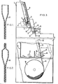
- the pipette-forming device (Fig 5) comprises a heating arrangement including parallel spaced apart tubes 22 each tube having a plurality of through bores 23 opposed to those of the other tube.
- the tubes 22 are connected to an air blower 24.
- Each tube contains a central heater element 25.
- hot air is blown out of the bores 23 to opposite sides of a row of supplied heat-shrinkable tubes A lying parallel to each other and extending upwards within the shell of the pipette-forming device 16.
- the motor 4 drives the bevel gears 5 to cause the holder 2 to be moved downwards and insert the lower ends of the attaching rods la into the upper opening of the pipette-forming device 16. They enter upper endsof tubes A as the tubes A are supported by the feed rollers 19. Rotation of the feed rollers 19 shifts the upper ends of tubes A upwards so as to set each firmly on its attached rod la. As this is taking place, motor 4 is reversed and drives holder 2 upwards to a small extent attaching rods la and the tubes A also move upwards. Heated air is then on the outside of tubes A via 24, 22 and 23 so that the upper portions Al of the tubes A are sligtly shrunk and thus fixed firmly to the attaching rods la.
- Feed rollers 19 continue to supply the tubes A upwardly. However, in the next stage the attaching rods la are upwardly moved even faster by control of motor 4.
- Blower 24 is switched off and the heater 25 is disengergized.
- a vacuum pump 28 pulls air thorugh bores 26 in the shell and into the forming device, thereby cooling the portion A3.
- Feed rollers 19 are actuated again, at the same speed as that of the attaching rods la so as to supply the tubes A upwards.
- the attachign rods la and feed rollers 19 are stopped.
- the portions A3 are then cut from the bodies of the tubes A by cutter 20.
- the motor 4 is next drive again in the direction such as to draw up the attachin rods la to a setting level.
- the feed roller 19 is driven in reverse until the remaining portion A4 of the tube A is pulled back almost to the bottom opening of the pipette-forming device 16.
- the remaining portions A4 are cut from the bodies of the tubes A by knife 21 and drop down as waste into the receiver 17.
- the pump 28 is switched off.
- the pipette-forming device 16 and receiver 17 are jointly horizontally moved and a portion 17a formed in the receiver 17 (separate from the waste container for portions A4) is positioned under micro-pipettes B still attached to the attaching rods la.
- micro-pipettes B are produced utilising operating steps mentioned above.
- the micro-pipette produced has a long "nose" of small internal diameter uniform along its length, (for example, between 0.3 and 0.7 mm) thereby to exhibit a long visible measuring display even with only small amounts of test material.
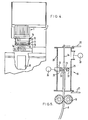
- the second embodiment of equipment further includes a device for sub-dividing test material such as sera.
- the head block 1 comprises a plurality of cylinders lb each connected to one of attaching rods la all of which are hollow.
- the cylinders lb each enclose a piston ld, all of which are connected to a rack member 30.
- the rack teeth are engaged with a pinion gear 31 driven by a motor 32 attached to the framne3.
- the pistons ld and thus the attached rack member 30 are jointly slidably supported in bearings 33 mounted on the holder 2.
- a belt conveyor 34 with a pair of endless belts 34a stretched between wheels 34b and 34c.
- a pair of parallel guide rails 35 are disposed along the top of the endless belts 34a, so as to guide a stocker 36 on the conveyer 34, as described below.
- Means 37 for feeding stockers 36 from a stack to the conveyor 34 one by one, and means 38 for accumulating the stockers 36 one by one in another stack are provided to the front and rear portions of the base frame 15.
- Operation may be a substage of that described above for pipette formation.
- the micro-pipettes B are moved downwards (by selectively driving the motor 4) when one of the stockers 36 arrives on conveyor 34 under the head block 1.
- the pipettes thus enter sample containers 39a in the stocker 36.
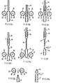
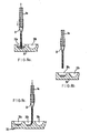
- the motor 32 operates the rack member 30 is shifted so as to such test material upwards and withdraws pistons ld into the pipettes as shown in Figure 8a.
- micro-pipettes B are jointly lifted by the motor 4 acting in reverse as shown in Figure 8(b).
- the conveyor 34 is then driven stepwise so that the stocker 36 is transferred step by step at a prescribed pitch.
- micro-pipettes B are then jointly lowered by the motor 4 so as to be inserted into the next row of sample containers 39b (figure 8c) and the motor 32 and rack 30 is moved to express the sample in the pipette, over as many subdivisional steps as necessary.
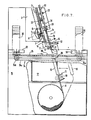
- the device comprises a vertical screw-threaded shaft 40 supported on a frame 41 and rotatable by driving motor 4 2.
- Guide rails 43 are disposed parallel to the shaft 40.
- a carriage 44 is movable relative to the frame 41 is movable relative to the frame 41 in a vertical direction along the rails 43 because its holder 44a engages to the shaft 40.
- a sub-carriage 45 is also movable relative to the carriage 44 in a vertical direction, by virtue of its holder 45a turnably engaging to a screw-threaded shaft 46 supported in bearings 47 attached to the carriage 44 and rotatable by driving motor 48 carried on the carriage 44.
- the device further has a guide rod 52 arranged in parallel to each piston 50b being engaged therewith by means of an engaging member 53.
- a contact roller surface 54 is provided at the top end of each guide rod 52, and a spring member 55 surrounds each guide rod to bias the engaging member 53 upwards.
- the guide rods 52 together with the pistons 50b are slidably supported in a direction inclined to that of the movement of the carriage 44 at a preselected or selectable angle.
- the sub-carriage 45 includes an adjuster 56 attached to the front at the top of the sub-carriage 45.
- Push members 57 corresponding one to each of the guide rods 52 are pivoted to the adjuster 56 by means of pins 58 and push the contact toller surfaces 54 individually, in dependence upon the setting of adjusting screws 59 threaded through the adjuster 56, which settings may be individually adjusted.
- FIG. 10(a) The relation between the inclinations and the piston strokes of the piston/cylinder assemblies 50, when the sub-carriage 45 is vertically moved by the motor driving motion, is illustrated by two examples shown in Figure 10(a) and (b).
- the example shown in Figure 10(a) has a small piston stroke for the constant stroke L of the sub-carriage 45, being the case where one of the push members 57 is adjusted at a large angle XA.
- FIG. 10 (b) has a large piston stroke for the same constant stroke L of the sub-carriage 45 since its the push member 57 is adjusted at a small angle XB.
Priority Applications (1)
| Application Number | Priority Date | Filing Date | Title |
|---|---|---|---|
| EP19840308120 EP0182943A1 (fr) | 1984-11-22 | 1984-11-22 | Micro-pipette et dispositif pour sa fabrication |
Applications Claiming Priority (1)
| Application Number | Priority Date | Filing Date | Title |
|---|---|---|---|
| EP19840308120 EP0182943A1 (fr) | 1984-11-22 | 1984-11-22 | Micro-pipette et dispositif pour sa fabrication |
Publications (1)
| Publication Number | Publication Date |
|---|---|
| EP0182943A1 true EP0182943A1 (fr) | 1986-06-04 |
Family
ID=8192820
Family Applications (1)
| Application Number | Title | Priority Date | Filing Date |
|---|---|---|---|
| EP19840308120 Withdrawn EP0182943A1 (fr) | 1984-11-22 | 1984-11-22 | Micro-pipette et dispositif pour sa fabrication |
Country Status (1)
| Country | Link |
|---|---|
| EP (1) | EP0182943A1 (fr) |
Cited By (19)
| Publication number | Priority date | Publication date | Assignee | Title |
|---|---|---|---|---|
| US4721680A (en) * | 1986-08-11 | 1988-01-26 | Multi-Technology, Inc. | Methods of using micro pipette tips |
| EP0257339A2 (fr) * | 1986-08-11 | 1988-03-02 | Multi-Technology, Inc. | Embouts pour micro-pipettes médicales pour endroits difficiles d'accès et procédés liés |
| US5032343A (en) * | 1986-08-11 | 1991-07-16 | Multi-Technology, Inc | Method for producing medical micro pipette tips for difficult to reach places |
| WO1992021508A1 (fr) * | 1991-05-31 | 1992-12-10 | Hr-Plast Oy | Procede servant a etirer sous forme de pipette une piece brute en plastique |
| EP0520797A2 (fr) * | 1991-06-25 | 1992-12-30 | Helena Laboratories Corporation | Système d'introduction de tube flexible dans un dispositif d'inserts à pompe pour éprouvettes |
| US5209882A (en) * | 1989-12-05 | 1993-05-11 | Sunstar Kabushiki Kaisha | Means and method for forming syringe |
| DE4209620C1 (de) * | 1992-03-25 | 1993-12-16 | Eppendorf Geraetebau Netheler | Verfahren zur Korrektur des Volumenfehlers ïV bei einem Pipettiersystem |
| EP0588236A2 (fr) * | 1992-09-18 | 1994-03-23 | Mitsubishi Yuka Bio-Clinical Laboratories, Inc. | Dispositif de distribution de liquides |
| US5453246A (en) * | 1992-09-18 | 1995-09-26 | Mitsubishi Yuka Bio-Clinical Laboratories, Inc. | Dispensing apparatus |
| US5623106A (en) * | 1995-06-06 | 1997-04-22 | Johnson & Johnson Clinical Diagnostics, Inc. | Method and apparatus for forming disposable tips in an analyzer |
| WO1997019804A1 (fr) * | 1995-11-29 | 1997-06-05 | Denjaru Plast Aps | Appareil d'extension d'une preforme |
| WO2003061831A2 (fr) * | 2002-01-25 | 2003-07-31 | Dormann Joerg Martin | Dispositif de prelevement d'echantillons et procede de determination quantifiable simultanee de germes infectieux |
| WO2007022584A1 (fr) * | 2005-08-26 | 2007-03-01 | Miles Athol Blackwood-Sewell | Buse de pipette |
| WO2007071088A1 (fr) * | 2005-12-20 | 2007-06-28 | Tpp Techno Plastic Products Ag | Pipette |
| CN101486437B (zh) * | 2008-01-18 | 2011-09-21 | 南京理工大学 | 微喷嘴制作方法 |
| ITTO20111066A1 (it) * | 2011-11-18 | 2012-02-17 | Giacalone Andrea | Dispositivo per cannucce di pipettaggio, per campioni da laboratorio di analisi, o altro. |
| CN101653986B (zh) * | 2009-09-15 | 2012-07-25 | 袁建华 | 一种通用聚苯乙烯移液管管嘴自动拉伸机 |
| CN114321519A (zh) * | 2020-09-28 | 2022-04-12 | 南京菲斯特焊接科技有限公司 | 一种变径塑料软管及成型方法 |
| CN114753985A (zh) * | 2022-04-22 | 2022-07-15 | 深圳市恒永达科技股份有限公司 | 一种自适应空气式移液泵、高精度移液方法及存储介质 |
Citations (3)
| Publication number | Priority date | Publication date | Assignee | Title |
|---|---|---|---|---|
| US3141336A (en) * | 1961-03-08 | 1964-07-21 | Beckman Instruments Inc | Pipette |
| US3737501A (en) * | 1968-04-22 | 1973-06-05 | Owens Illinois Inc | Method of forming plastic tubular articles |
| FR2447751A1 (fr) * | 1979-01-30 | 1980-08-29 | Faure Jean | Elements interchangeables pour transfert de liquides et procede d'utilisation desdits elements |
-
1984
- 1984-11-22 EP EP19840308120 patent/EP0182943A1/fr not_active Withdrawn
Patent Citations (3)
| Publication number | Priority date | Publication date | Assignee | Title |
|---|---|---|---|---|
| US3141336A (en) * | 1961-03-08 | 1964-07-21 | Beckman Instruments Inc | Pipette |
| US3737501A (en) * | 1968-04-22 | 1973-06-05 | Owens Illinois Inc | Method of forming plastic tubular articles |
| FR2447751A1 (fr) * | 1979-01-30 | 1980-08-29 | Faure Jean | Elements interchangeables pour transfert de liquides et procede d'utilisation desdits elements |
Cited By (25)
| Publication number | Priority date | Publication date | Assignee | Title |
|---|---|---|---|---|
| US4721680A (en) * | 1986-08-11 | 1988-01-26 | Multi-Technology, Inc. | Methods of using micro pipette tips |
| EP0257339A2 (fr) * | 1986-08-11 | 1988-03-02 | Multi-Technology, Inc. | Embouts pour micro-pipettes médicales pour endroits difficiles d'accès et procédés liés |
| EP0257339A3 (en) * | 1986-08-11 | 1988-08-10 | Multi-Technology, Inc. | Medical micro pipette tips for difficult to reach places and related methods |
| US5032343A (en) * | 1986-08-11 | 1991-07-16 | Multi-Technology, Inc | Method for producing medical micro pipette tips for difficult to reach places |
| US5209882A (en) * | 1989-12-05 | 1993-05-11 | Sunstar Kabushiki Kaisha | Means and method for forming syringe |
| WO1992021508A1 (fr) * | 1991-05-31 | 1992-12-10 | Hr-Plast Oy | Procede servant a etirer sous forme de pipette une piece brute en plastique |
| EP0520797A2 (fr) * | 1991-06-25 | 1992-12-30 | Helena Laboratories Corporation | Système d'introduction de tube flexible dans un dispositif d'inserts à pompe pour éprouvettes |
| EP0520797A3 (en) * | 1991-06-25 | 1993-03-10 | Helena Laboratories Corporation | Tube feed system for test tube pump inserter |
| DE4209620C1 (de) * | 1992-03-25 | 1993-12-16 | Eppendorf Geraetebau Netheler | Verfahren zur Korrektur des Volumenfehlers ïV bei einem Pipettiersystem |
| EP0588236A2 (fr) * | 1992-09-18 | 1994-03-23 | Mitsubishi Yuka Bio-Clinical Laboratories, Inc. | Dispositif de distribution de liquides |
| EP0588236A3 (fr) * | 1992-09-18 | 1994-08-31 | Mitsubishi Yuka Bio Clinical L | |
| US5453246A (en) * | 1992-09-18 | 1995-09-26 | Mitsubishi Yuka Bio-Clinical Laboratories, Inc. | Dispensing apparatus |
| US5623106A (en) * | 1995-06-06 | 1997-04-22 | Johnson & Johnson Clinical Diagnostics, Inc. | Method and apparatus for forming disposable tips in an analyzer |
| WO1997019804A1 (fr) * | 1995-11-29 | 1997-06-05 | Denjaru Plast Aps | Appareil d'extension d'une preforme |
| WO2003061831A2 (fr) * | 2002-01-25 | 2003-07-31 | Dormann Joerg Martin | Dispositif de prelevement d'echantillons et procede de determination quantifiable simultanee de germes infectieux |
| WO2003061831A3 (fr) * | 2002-01-25 | 2004-04-01 | Joerg Martin Dormann | Dispositif de prelevement d'echantillons et procede de determination quantifiable simultanee de germes infectieux |
| WO2007022584A1 (fr) * | 2005-08-26 | 2007-03-01 | Miles Athol Blackwood-Sewell | Buse de pipette |
| GB2444435A (en) * | 2005-08-26 | 2008-06-04 | Miles Athol Blackwood-Sewell | Pipette jet |
| WO2007071088A1 (fr) * | 2005-12-20 | 2007-06-28 | Tpp Techno Plastic Products Ag | Pipette |
| US8113067B2 (en) | 2005-12-20 | 2012-02-14 | Tpp Techno Plastic Products Ag | Pipette |
| CN101486437B (zh) * | 2008-01-18 | 2011-09-21 | 南京理工大学 | 微喷嘴制作方法 |
| CN101653986B (zh) * | 2009-09-15 | 2012-07-25 | 袁建华 | 一种通用聚苯乙烯移液管管嘴自动拉伸机 |
| ITTO20111066A1 (it) * | 2011-11-18 | 2012-02-17 | Giacalone Andrea | Dispositivo per cannucce di pipettaggio, per campioni da laboratorio di analisi, o altro. |
| CN114321519A (zh) * | 2020-09-28 | 2022-04-12 | 南京菲斯特焊接科技有限公司 | 一种变径塑料软管及成型方法 |
| CN114753985A (zh) * | 2022-04-22 | 2022-07-15 | 深圳市恒永达科技股份有限公司 | 一种自适应空气式移液泵、高精度移液方法及存储介质 |
Similar Documents
| Publication | Publication Date | Title |
|---|---|---|
| EP0182943A1 (fr) | Micro-pipette et dispositif pour sa fabrication | |
| US4487081A (en) | Pipetting techniques using replaceable tips | |
| EP0758923B1 (fr) | Appareil et procede pour systeme de pipettage a parallelisme eleve | |
| US3778351A (en) | Automatic bacterial specimen streaker | |
| US4728501A (en) | Adjustable liquid sampling apparatus | |
| US20060216781A1 (en) | Microarrayer with coaxial multiple punches | |
| US4287301A (en) | Method and apparatus for streaking agar | |
| CN211389140U (zh) | 一种木头切割用自动上料结构 | |
| US3950920A (en) | Collecting system for batchwise collection of rod-shaped objects | |
| CN111015803A (zh) | 薄膜全自动冲膜裁切机 | |
| CN112845994B (zh) | 一种钢筋自动化切割方法 | |
| WO2011029923A1 (fr) | Dispositif de séparation et procédé de séparation | |
| EP0278683B1 (fr) | Dispositif automatique de nettoyage pour un plastomètre à extrusion pour matériaux thermoplastiques | |
| GB2070999A (en) | Methods of and apparatus for making lengths of tubing from cylindrical tubes | |
| CN217626157U (zh) | 一种纤维棉自动落料送料装置 | |
| EP0588236B1 (fr) | Dispositif de distribution de liquides | |
| JP4158138B2 (ja) | 縦押し成形方法 | |
| CN211682470U (zh) | 薄膜全自动冲膜裁切机 | |
| CN210551446U (zh) | 切割定距细管的自动化设备 | |
| CN218018659U (zh) | 香条切割装置以及香条生产设备 | |
| US5623106A (en) | Method and apparatus for forming disposable tips in an analyzer | |
| CN108818726B (zh) | 整卷膜片切割设备 | |
| CN219996675U (zh) | 一种粮食种子切片染色设备 | |
| US4513647A (en) | Portable pneumatic wire cutter | |
| CA1084076A (fr) | Appareil de fabrication d'un membre cylindrique |
Legal Events
| Date | Code | Title | Description |
|---|---|---|---|
| PUAI | Public reference made under article 153(3) epc to a published international application that has entered the european phase |
Free format text: ORIGINAL CODE: 0009012 |
|
| AK | Designated contracting states |
Kind code of ref document: A1 Designated state(s): DE FR GB |
|
| 17P | Request for examination filed |
Effective date: 19861204 |
|
| 17Q | First examination report despatched |
Effective date: 19880718 |
|
| STAA | Information on the status of an ep patent application or granted ep patent |
Free format text: STATUS: THE APPLICATION IS DEEMED TO BE WITHDRAWN |
|
| 18D | Application deemed to be withdrawn |
Effective date: 19881129 |