EP0182471A2 - Inspection apparatus with a scanning beam of radiation - Google Patents
Inspection apparatus with a scanning beam of radiation Download PDFInfo
- Publication number
- EP0182471A2 EP0182471A2 EP85306637A EP85306637A EP0182471A2 EP 0182471 A2 EP0182471 A2 EP 0182471A2 EP 85306637 A EP85306637 A EP 85306637A EP 85306637 A EP85306637 A EP 85306637A EP 0182471 A2 EP0182471 A2 EP 0182471A2
- Authority
- EP
- European Patent Office
- Prior art keywords
- image
- area
- focused image
- areas
- radiation
- Prior art date
- Legal status (The legal status is an assumption and is not a legal conclusion. Google has not performed a legal analysis and makes no representation as to the accuracy of the status listed.)
- Granted
Links
Images


Classifications
-
- G—PHYSICS
- G01—MEASURING; TESTING
- G01N—INVESTIGATING OR ANALYSING MATERIALS BY DETERMINING THEIR CHEMICAL OR PHYSICAL PROPERTIES
- G01N21/00—Investigating or analysing materials by the use of optical means, i.e. using sub-millimetre waves, infrared, visible or ultraviolet light
- G01N21/84—Systems specially adapted for particular applications
- G01N21/88—Investigating the presence of flaws or contamination
- G01N21/89—Investigating the presence of flaws or contamination in moving material, e.g. running paper or textiles
- G01N21/8901—Optical details; Scanning details
Definitions
- the present invention relates to inspection apparatus.
- the apparatus may be of a type for inspecting an object for example for inspecting its surface or, if the object is transparent to the radiation used in the inspection, for inspecting the bulk of the object. Preferred arrangements of the apparatus are particularly applicable to the inspection of sheet material.
- Our previous patent 2 054 835 disclosed an inspection apparatus in which two beams of light which have been influenced by different portions of an object were passed to a grating 14, the two beams being spaced at the grating by an uneven number of widths "w" which correspond to the widths of the alternate light and dark areas of the grating.
- Light collected from the grating would be of a constant amplitude so long as the two beams are spaced apart by that exact distance, but faults or flaws in the object under test would cause the distance between the two beams to change and therefore cause a difference in the light received from the grating. This could be used to indicate a fault or flaw in the object or surface under test.
- the arrangement only deals with deflections of the beam in one plane so that deflections in the plane of Figure 3 are detected, but deflections at right angles to the plane of Figure 3 would not be detected and certain defects would therefore not be detected.
- the arrangement only looks at faults on the surface of the wafer because an image of the surface itself is formed at the detector 38 (this is not totally clear but would seem likely from the ray diagram in Figure 1) and so the arrangement is not suitable for examining, for example, transparent objects in which the beam passes through the object.
- the present invention has been based on the realisation that if a beam of light is passed to the object and is either reflected therefrom or transmitted therethrough, faults in the object will cause changes in the beam, for example, deflection of the beam, scattering of the beam or attenuation of the beam. If the affected beam is then passed to, for example, a screen, we can examine the image of the beam and from that image of the beam we can analyse the faults in the object. This is rendered simpler if we are able to examine this image through the scanning system so as to "descan" the image.
- the present invention provides inspection apparatus for inspecting an object comprising means for scanning a beam of radiation across an object under test, means for receiving the beam of radiation and forming an image thereon after the beam has been influenced (eg by refraction, reflection, transmission) by said object, means for examining the image formed by the beam on the receiving means comprising focusing means for forming a focused image of said image on a detector means via the scanning means, the detector means being sensitive to changes in the position and/or intensity of the image formed thereon caused by the influence of the object.
- radiation may be taken to be radiation of any wavelength but particularly optical light or ultra violet or infra red radiation.
- Various apparatus of the invention may be produced to inspect a variety of objects which influence the beam of radiation, for example the surface of sheet material which reflects at least a proportion of the incident beam or the body of sheet material which transmits the beam.
- the apparatus may be used to inspect, for example, sheet material such as tin plate, plastic film, glass or the like.
- the means for receiving the beam of radiation comprises a scattering screen, which may be for example, paper or ground glass.
- the screen may comprise a retro-reflective screen.
- the detector means preferably includes an analyser means for analysing the focused image.
- the detector means may include two areas, one of which influences the focused image in a different way to the other, the focused image being passed to one of the areas when the object under test is normal and being deflected to or toward the other area when the focused image is influenced by a fault in the object under test.
- one of the two areas may have at least one dimension which generally corresponds to the outer dimension of the focused image where it strikes the area so that any deflection of the focused image away from the first area causes the focused image to pass into the second area adjacent the second area.
- One of the areas is preferably the same shape as the cross section of the focused image and the other of the areas is next to or surrounds the first area.
- the apparatus comprises a laser 11 and beam shaping optical components 11A for producing a beam 12.
- the beam 12 passes through a beam splitter 31 in the form of a mirror having a central aperture 22A through which the beam from the laser 11 passes.
- the beam is reflected from a mirror drum scanner 22 mounted inside a hood 22A (see Figure 1) so as to scan the beam 12 through a slot 30 in a box 35 containing the laser and optical components transversely across the object 13 under inspection which in this case may be a sheet of transparent material 13.
- the sheet of material 13 is moving at right angles to the line of scan as illustrated by the arrows 10 in Figure 2 whereby the whole of the sheet 13 may be inspected by means of a combination of scanning movement of the beam and movement of the sheet 11.
- the mirror drum scanner 22 thus causes the light beam 12 to scan from one edge of the sheet 13 to the other as shown in Figure 1.
- a retro-reflective sheet 24 which extends behind the sheet 13 where an image 15 of the incident beam which is passed through the sheet 13 is formed.
- the image 15 is not a focused image but is actually simply a cross section of the form of the beam where it strikes the sheet 24.
- the slightly scattered retro-reflected beam passes back to the sheet 13, passes through the sheet 13 and onto the mirror drum scannor 22 where the scanning motion is cancelled, to the beam splitter 31 where it is reflected and is collected by collection lens 32.
- the outward beam from the laser it is very narow and passes through the aperture 22A of the beam splitter 31 but the returning beam is scattered and is intercepted by all of the mirror surface of the beam splitter 31.
- the retro-reflective layer 24 and the target apparatus 33 are at conjugate points with respect to the lens 32 so that a focused image 25 of the image 15 is formed by the lens 32 onto a target apparatus 33.
- the focused image 25 is a genuine focused image of the part of the surface of the retro-reflected layer 14 which the image 15, in normal circumstances, will occupy.
- the target apparatus 33 comprises the ends of optical fibres 33A and light passes through these fibres to respective photomultipliers 27.
- the beam 12 passing from the mirror drum 22 to the retro-reflective layer 24 has a very small cross section (typically 0.25 to 0.5 mm diameter at the sheet 13). Thus even small defects in the sheet 13 will severely affect the beam. In normal circumstances the beam then passes to the retroreflector at which point it is about 3mm in diameter (in the case where the sheet 13 is separated from the retro-reflector 24 by about 1 metre) and the retro-reflector reflects the beam with an angle of scatter of about 1 to 2° so that when the beam reaches the sheet 13 again its diameter is about 30mm. In practice as the facets of the mirror drum are normally about 2.5 x 5 cm these define the cone of light which will be received by beam splitter 31 and the lens 32.
- the returning beam from the retro-reflector 24 is very much larger and thus only a very small part of the reflected beam from the retro-reflector 24 is affected by the same fault.
- the fault in the sheet 13 deflects the beam 12 then the retro-reflector 24 will retro-reflect the beam back to the sheet 13 with a degree of scattering and the majority of the returning beam will not be affected the second time by the defect and will therefore not pass back to the mirror drum 22.
- the beam path from the laser to the scanner 22 does not move then the beam path from the scanner 22 to the beam splitter and hence the target 33 similarly does not move when the sheet 13 does not deflect the beam and so the focused image 25 remains stationary on the target 33.
- FIG 4 A front view of the target apparatus 33 is shown in Figure 4.
- a first area in the form of a central circle 36 of material which transmits half of the incident beam.
- the central circle 36 is surrounded by an outer annulus 37 which transmits all of the incident beam.
- the image 25 of the beam is shown at 12.
- Figure 4A it will be understood that the outline of the image 25 is equal to or less than the diameter of the central circle 36 and so long as the sheet material does not have any faults or flaws which deflect the beam then the image 25 will remain in the central circle 36.
- Figure 5 shows the signal output corresponding to Figures 4A to 4E.
- the beam passes through an absorbing defect in the sheet 13 then the light received by the photomultipler 27 will be reduced as is indicated by the signal at C in Figure 5. If the beam 12 passes through a portion of the sheet 13 which includes a defect which deflects the beam then the image 15 will move away from the portion it would otherwise hold and hence the image 25 will be deflected away from the central circle 36 into the outer annulus 37 and hence the light passing through to the photomultiplier 27 will be increased as is shown at D in Figure 5. Indeed deflections of the beam in any direction as shown at E in Figure 11 will produce an increase in the signal produced by the photomultiplier 27.
- This latter arrangement therefore has the advantage that deflection of the beam in any direction by the sheet 13 will be readily indicated.
- Figures 6 and 7 illustrate an alternative arrangement of the target apparatus 33 in which other types of fault in the sheet material 13 can be detected.
- a further annulus 38 is provided surrounding the outer annulus 37 and the light in this further annulus 38 is collected separately then an analysis of the light collected in this further annulus 38 will give an indication of the type of flaw or fault in the sheet material 13.
- some faults or flaws in the sheet material 13 such as scratches will scatter the light thus forming a larger image 15 on the retro-reflective layer 14 and this the focused image 25 of this larger image 15 will be picked up by the further annulus 38.
- the signal output for this further annulus 38 is shown in Figure 7.
- At F and G there are shown the effects on the signal output of the further annulus 38 for vertical and horizontal scratches 41,42.
- this will also be picked up by the further annulus 38.
- the apparatus is that there is good ambient light rejection because the detector is only looking at a focused image 25 of the position which the image 15 occupies or should occupy, there is a sensitivity to all types of distortion, ie distortion causing the image 15 to move along or transverse to the direction of scanning and fine scratches and small inclusions can also be detected by the further annulus 38.
- the apparatus is almost completely free of the need for accurate registration between the scanning head and the simple retroreflective screen since the field of view of the collection system is the same as that of the projection system.
- the target 33 comprises three separate areas 50, 51, 52 which are provided by the ends of three optical fibres 53, 54, 55 respectively.
- Area 51 corresponds to both areas 36 and 37 of Figure 6 and the two areas 50, 52 correspond to the area 38 of Figure 6. It will be noted that the outer coating 57 of the three optical fibres 53, 54, 55 are cut away where the three fibres 53, 54, 55 abut so as to form a continuous surface.
- Optical fibres 53 and 55 are joined together and passed to one detector and optical fibre 34 passes to a second photodetector.
- target filter could also be used such as a circularly graded neutral density area with the darkest area in the centre so that the distortion aspect could be further classified in intensity.
- the apparatus with respect to a retro-reflecting surface 24 the arrangement would operate with a simple scattering screen such as a paper surface or a ground glass screen.
- the retro-reflecting layer 24 allows the collection of a greater proportion of the incident light.
- Reflective material may also be inspected in which case the beam reflected from the surface would be passed to a retro-reflector 24 and thence back to be reflected again by the surface before being collected by the mirror drum 22.
Abstract
Description
- The present invention relates to inspection apparatus.
- The apparatus may be of a type for inspecting an object for example for inspecting its surface or, if the object is transparent to the radiation used in the inspection, for inspecting the bulk of the object. Preferred arrangements of the apparatus are particularly applicable to the inspection of sheet material.
- Our previous patent 2 054 835 disclosed an inspection apparatus in which two beams of light which have been influenced by different portions of an object were passed to a grating 14, the two beams being spaced at the grating by an uneven number of widths "w" which correspond to the widths of the alternate light and dark areas of the grating. Light collected from the grating would be of a constant amplitude so long as the two beams are spaced apart by that exact distance, but faults or flaws in the object under test would cause the distance between the two beams to change and therefore cause a difference in the light received from the grating. This could be used to indicate a fault or flaw in the object or surface under test.
- Although such a system operates satisfactorily there are a number of difficulties. Where a sheet material is to be inspected which is of considerable width, then a grating 14 of the same width as the sheet material must be provided. This increases the cost and complexity of the apparatus. Furthermore a cylindrical lens 26 is utilised and once again the cylindrical lens is an expensive component and the length must be sufficient so as to enable the whole of the width of the sheet material to be scanned.
- Furthermore, the arrangement only deals with deflections of the beam in one plane so that deflections in the plane of Figure 3 are detected, but deflections at right angles to the plane of Figure 3 would not be detected and certain defects would therefore not be detected.
- Another inspection apparatus is described in US specification 3 790 287. Somewhat similar problems arise with this arrangement. There is described an apparatus for examining a silicon wafer which of course is of limited size. Thus the scanned beam passing to the wafer 28 passes through a lens system 26 which must clearly be of sufficient lateral extent so as to be able to receive the beam at the extremes of its scanning path. Clearly such an arrangement is limited to examination of quite small objects and would not be suitable for large sheets.
- Furthermore, the arrangement only looks at faults on the surface of the wafer because an image of the surface itself is formed at the detector 38 (this is not totally clear but would seem likely from the ray diagram in Figure 1) and so the arrangement is not suitable for examining, for example, transparent objects in which the beam passes through the object.
- The present invention has been based on the realisation that if a beam of light is passed to the object and is either reflected therefrom or transmitted therethrough, faults in the object will cause changes in the beam, for example, deflection of the beam, scattering of the beam or attenuation of the beam. If the affected beam is then passed to, for example, a screen, we can examine the image of the beam and from that image of the beam we can analyse the faults in the object. This is rendered simpler if we are able to examine this image through the scanning system so as to "descan" the image.
- The present invention provides inspection apparatus for inspecting an object comprising means for scanning a beam of radiation across an object under test, means for receiving the beam of radiation and forming an image thereon after the beam has been influenced (eg by refraction, reflection, transmission) by said object, means for examining the image formed by the beam on the receiving means comprising focusing means for forming a focused image of said image on a detector means via the scanning means, the detector means being sensitive to changes in the position and/or intensity of the image formed thereon caused by the influence of the object.
- It should be understood that although faults or flaws in the object are referred to there may be certain circumstances in which the particular fault or flaw may comprise a deliberately produced feature of the object under test. The term "radiation" may be taken to be radiation of any wavelength but particularly optical light or ultra violet or infra red radiation.
- Various apparatus of the invention may be produced to inspect a variety of objects which influence the beam of radiation, for example the surface of sheet material which reflects at least a proportion of the incident beam or the body of sheet material which transmits the beam. Thus the apparatus may be used to inspect, for example, sheet material such as tin plate, plastic film, glass or the like.
- Preferably the means for receiving the beam of radiation comprises a scattering screen, which may be for example, paper or ground glass. Alternatively the screen may comprise a retro-reflective screen. An advantage of this arrangement is that most of the light from the beam striking the retro-reflective screen will be reflected back automatically to the scanning system.
- The detector means preferably includes an analyser means for analysing the focused image. The detector means may include two areas, one of which influences the focused image in a different way to the other, the focused image being passed to one of the areas when the object under test is normal and being deflected to or toward the other area when the focused image is influenced by a fault in the object under test.
- In this case one of the two areas may have at least one dimension which generally corresponds to the outer dimension of the focused image where it strikes the area so that any deflection of the focused image away from the first area causes the focused image to pass into the second area adjacent the second area. One of the areas is preferably the same shape as the cross section of the focused image and the other of the areas is next to or surrounds the first area.
- Preferred arrangements of the invention will now be described by way of example only and with reference to the accompanying drawings in which:
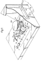
- Figure 1 is a perspective broken away isometric view of a part of a preferred inspection apparatus according to the invention,
- Figure 2 shows a front view in diagrammatic form of the apparatus of the invention,
- Figure 3 shows a side view of the apparatus of Figure 2,
- Figures 4A to 4E show diagrammatically the two areas used in the apparatus and the incidence of the beam on those two areas,
- Figure 5 shows a signal output,
- Figures 6A to 6E show alternative arrangements of Figure 4A to 4E,
- Figure 7 shows the signal output from the apparatus of Figure 6, and,
- Figure 8 shows an alternative arrangement of target apparatus,
- Referring to Figures 1,2 and 3, the apparatus comprises a laser 11 and beam shaping optical components 11A for producing a
beam 12. Thebeam 12 passes through abeam splitter 31 in the form of a mirror having acentral aperture 22A through which the beam from the laser 11 passes. The beam is reflected from amirror drum scanner 22 mounted inside ahood 22A (see Figure 1) so as to scan thebeam 12 through aslot 30 in abox 35 containing the laser and optical components transversely across theobject 13 under inspection which in this case may be a sheet oftransparent material 13. In this preferred arrangement the sheet ofmaterial 13 is moving at right angles to the line of scan as illustrated by the arrows 10 in Figure 2 whereby the whole of thesheet 13 may be inspected by means of a combination of scanning movement of the beam and movement of the sheet 11. Themirror drum scanner 22 thus causes thelight beam 12 to scan from one edge of thesheet 13 to the other as shown in Figure 1. - Light transmitted by the
sheet 13 is passed onto a retro-reflective sheet 24 which extends behind thesheet 13 where animage 15 of the incident beam which is passed through thesheet 13 is formed. In fact theimage 15 is not a focused image but is actually simply a cross section of the form of the beam where it strikes thesheet 24. - The slightly scattered retro-reflected beam passes back to the
sheet 13, passes through thesheet 13 and onto themirror drum scannor 22 where the scanning motion is cancelled, to thebeam splitter 31 where it is reflected and is collected bycollection lens 32. It will be noted that the outward beam from the laser it is very narow and passes through theaperture 22A of thebeam splitter 31 but the returning beam is scattered and is intercepted by all of the mirror surface of thebeam splitter 31. It is arranged that the retro-reflective layer 24 and thetarget apparatus 33 are at conjugate points with respect to thelens 32 so that a focusedimage 25 of theimage 15 is formed by thelens 32 onto atarget apparatus 33. Note that, whereas theimage 15 is simply the cross section of the beam at the retro-reflective layer 24, thefocused image 25 is a genuine focused image of the part of the surface of the retro-reflected layer 14 which theimage 15, in normal circumstances, will occupy. - The
target apparatus 33 comprises the ends ofoptical fibres 33A and light passes through these fibres torespective photomultipliers 27. - The
beam 12 passing from themirror drum 22 to the retro-reflective layer 24 has a very small cross section (typically 0.25 to 0.5 mm diameter at the sheet 13). Thus even small defects in thesheet 13 will severely affect the beam. In normal circumstances the beam then passes to the retroreflector at which point it is about 3mm in diameter (in the case where thesheet 13 is separated from the retro-reflector 24 by about 1 metre) and the retro-reflector reflects the beam with an angle of scatter of about 1 to 2° so that when the beam reaches thesheet 13 again its diameter is about 30mm. In practice as the facets of the mirror drum are normally about 2.5 x 5 cm these define the cone of light which will be received bybeam splitter 31 and thelens 32. However, it will be noted that although the small fault in thesheet 13 affects the beam from themirror drum 22, the returning beam from the retro-reflector 24 is very much larger and thus only a very small part of the reflected beam from the retro-reflector 24 is affected by the same fault. Thus if, for example, the fault in thesheet 13 deflects thebeam 12 then the retro-reflector 24 will retro-reflect the beam back to thesheet 13 with a degree of scattering and the majority of the returning beam will not be affected the second time by the defect and will therefore not pass back to themirror drum 22. It is only that very small proportion of the reflected beam which strikes the same defect which will be scattered back along the incident path to themirror drum 22 and this small proportion is of no consequence. - It will be understood that as the beam path from the laser to the
scanner 22 does not move then the beam path from thescanner 22 to the beam splitter and hence thetarget 33 similarly does not move when thesheet 13 does not deflect the beam and so thefocused image 25 remains stationary on thetarget 33. - A front view of the
target apparatus 33 is shown in Figure 4. In this case there is provided a first area in the form of acentral circle 36 of material which transmits half of the incident beam. Thecentral circle 36 is surrounded by anouter annulus 37 which transmits all of the incident beam. Theimage 25 of the beam is shown at 12. Referring now to Figure 4A it will be understood that the outline of theimage 25 is equal to or less than the diameter of thecentral circle 36 and so long as the sheet material does not have any faults or flaws which deflect the beam then theimage 25 will remain in thecentral circle 36. Figure 5 shows the signal output corresponding to Figures 4A to 4E. If the beam passes through an absorbing defect in thesheet 13 then the light received by thephotomultipler 27 will be reduced as is indicated by the signal at C in Figure 5. If thebeam 12 passes through a portion of thesheet 13 which includes a defect which deflects the beam then theimage 15 will move away from the portion it would otherwise hold and hence theimage 25 will be deflected away from thecentral circle 36 into theouter annulus 37 and hence the light passing through to thephotomultiplier 27 will be increased as is shown at D in Figure 5. Indeed deflections of the beam in any direction as shown at E in Figure 11 will produce an increase in the signal produced by thephotomultiplier 27. - This latter arrangement therefore has the advantage that deflection of the beam in any direction by the
sheet 13 will be readily indicated. - Figures 6 and 7 illustrate an alternative arrangement of the
target apparatus 33 in which other types of fault in thesheet material 13 can be detected. Thus if afurther annulus 38 is provided surrounding theouter annulus 37 and the light in thisfurther annulus 38 is collected separately then an analysis of the light collected in thisfurther annulus 38 will give an indication of the type of flaw or fault in thesheet material 13. For example some faults or flaws in thesheet material 13 such as scratches will scatter the light thus forming alarger image 15 on the retro-reflective layer 14 and this thefocused image 25 of thislarger image 15 will be picked up by thefurther annulus 38. The signal output for thisfurther annulus 38 is shown in Figure 7. At F and G there are shown the effects on the signal output of thefurther annulus 38 for vertical andhorizontal scratches sheet 13 which severely distorts thebeam 12 and hence theimages further annulus 38. - Advantages of the apparatus are that there is good ambient light rejection because the detector is only looking at a
focused image 25 of the position which theimage 15 occupies or should occupy, there is a sensitivity to all types of distortion, ie distortion causing theimage 15 to move along or transverse to the direction of scanning and fine scratches and small inclusions can also be detected by thefurther annulus 38. The apparatus is almost completely free of the need for accurate registration between the scanning head and the simple retroreflective screen since the field of view of the collection system is the same as that of the projection system. - An alternative arrangement using fibre optics to segment the target area and using a number of separate detectors to analyse the image.
- Referring to Figure 8 the
target 33 comprises threeseparate areas optical fibres Area 51 corresponds to bothareas areas area 38 of Figure 6. It will be noted that theouter coating 57 of the threeoptical fibres fibres -
Optical fibres - Various other forms of target filter could also be used such as a circularly graded neutral density area with the darkest area in the centre so that the distortion aspect could be further classified in intensity.
- This invention is not restricted to the details of the foregoing examples.
- Although we have described the apparatus with respect to a retro-reflecting
surface 24 the arrangement would operate with a simple scattering screen such as a paper surface or a ground glass screen. However the retro-reflectinglayer 24 allows the collection of a greater proportion of the incident light. - Furthermore the apparatus of the invention has been described with regard to the inspection of a
transparent sheet 13. Reflective material may also be inspected in which case the beam reflected from the surface would be passed to a retro-reflector 24 and thence back to be reflected again by the surface before being collected by themirror drum 22.
Claims (11)
Priority Applications (1)
| Application Number | Priority Date | Filing Date | Title |
|---|---|---|---|
| AT85306637T ATE67034T1 (en) | 1984-09-24 | 1985-09-18 | INVESTIGATION DEVICE WITH RADIATION SCANNING BEAM. |
Applications Claiming Priority (2)
| Application Number | Priority Date | Filing Date | Title |
|---|---|---|---|
| GB8424084 | 1984-09-24 | ||
| GB848424084A GB8424084D0 (en) | 1984-09-24 | 1984-09-24 | Inspection apparatus |
Publications (3)
| Publication Number | Publication Date |
|---|---|
| EP0182471A2 true EP0182471A2 (en) | 1986-05-28 |
| EP0182471A3 EP0182471A3 (en) | 1988-09-21 |
| EP0182471B1 EP0182471B1 (en) | 1991-09-04 |
Family
ID=10567173
Family Applications (1)
| Application Number | Title | Priority Date | Filing Date |
|---|---|---|---|
| EP85306637A Expired - Lifetime EP0182471B1 (en) | 1984-09-24 | 1985-09-18 | Inspection apparatus with a scanning beam of radiation |
Country Status (7)
| Country | Link |
|---|---|
| US (1) | US4737650A (en) |
| EP (1) | EP0182471B1 (en) |
| JP (1) | JPS61159139A (en) |
| AT (1) | ATE67034T1 (en) |
| CA (1) | CA1259390A (en) |
| DE (1) | DE3583989D1 (en) |
| GB (1) | GB8424084D0 (en) |
Cited By (7)
| Publication number | Priority date | Publication date | Assignee | Title |
|---|---|---|---|---|
| EP0259036A2 (en) * | 1986-09-05 | 1988-03-09 | Sira Limited | Inspection apparatus |
| WO1988007190A1 (en) * | 1987-03-09 | 1988-09-22 | Battelle Memorial Institute | Optical inspection system for cylindrical objects |
| WO1990005907A2 (en) * | 1988-11-23 | 1990-05-31 | Sira Limited | Inspection apparatus |
| EP0379281A2 (en) * | 1989-01-19 | 1990-07-25 | Cosmopolitan Textile Company Limited | Web inspecting method and apparatus |
| EP0408337A1 (en) * | 1989-07-13 | 1991-01-16 | De La Rue Systems Limited | Sheet inspection method and apparatus |
| EP0244102B1 (en) * | 1986-04-28 | 1991-09-04 | Sira Limited | Inspection apparatus |
| EP0556987A1 (en) * | 1992-02-13 | 1993-08-25 | AT&T Corp. | Coating defect detection system based on light scattering outside the expected region |
Families Citing this family (16)
| Publication number | Priority date | Publication date | Assignee | Title |
|---|---|---|---|---|
| US4930872A (en) * | 1988-12-06 | 1990-06-05 | Convery Joseph J | Imaging with combined alignment fixturing, illumination and imaging optics |
| US5103106A (en) * | 1990-09-11 | 1992-04-07 | Moshe Golberstein | Reflective optical instrument for measuring surface reflectance |
| US5220617A (en) * | 1991-09-04 | 1993-06-15 | International Business Machines Corporation | Method and apparatus for object inspection |
| US5216485A (en) * | 1991-09-04 | 1993-06-01 | International Business Machines Corporation | Advanced via inspection tool (avit) |
| US5847834A (en) * | 1997-09-11 | 1998-12-08 | Webview, Inc. | Expandable, continuous illumination source for a web inspection assembly and method |
| US7023542B2 (en) * | 2002-04-03 | 2006-04-04 | 3M Innovative Properties Company | Imaging method and apparatus |
| CA2608119A1 (en) | 2005-05-11 | 2006-11-16 | Optosecurity Inc. | Method and system for screening luggage items, cargo containers or persons |
| US7991242B2 (en) | 2005-05-11 | 2011-08-02 | Optosecurity Inc. | Apparatus, method and system for screening receptacles and persons, having image distortion correction functionality |
| US20070041613A1 (en) * | 2005-05-11 | 2007-02-22 | Luc Perron | Database of target objects suitable for use in screening receptacles or people and method and apparatus for generating same |
| ES2293786B2 (en) * | 2005-07-12 | 2008-11-16 | Universidad De Vigo | DYNAMIC DEFORMED SCANNER. |
| US7899232B2 (en) | 2006-05-11 | 2011-03-01 | Optosecurity Inc. | Method and apparatus for providing threat image projection (TIP) in a luggage screening system, and luggage screening system implementing same |
| US8494210B2 (en) | 2007-03-30 | 2013-07-23 | Optosecurity Inc. | User interface for use in security screening providing image enhancement capabilities and apparatus for implementing same |
| NO336546B1 (en) * | 2010-09-24 | 2015-09-21 | Tomra Sorting As | Apparatus and method for inspection of matter |
| KR102067367B1 (en) | 2011-09-07 | 2020-02-11 | 라피스캔 시스템스, 인코포레이티드 | X-ray inspection method that integrates manifest data with imaging/detection processing |
| US9495571B1 (en) | 2015-09-30 | 2016-11-15 | Datalogic Automation, Inc. | Two-dimensional representation of linear barcode derived from laser barcode scanner scanline data |
| EP3420563A4 (en) | 2016-02-22 | 2020-03-11 | Rapiscan Systems, Inc. | Systems and methods for detecting threats and contraband in cargo |
Citations (4)
| Publication number | Priority date | Publication date | Assignee | Title |
|---|---|---|---|---|
| US3743431A (en) * | 1972-05-09 | 1973-07-03 | Philco Ford Corp | Radiation sensitive means for detecting flaws in glass |
| US3790287A (en) * | 1972-03-31 | 1974-02-05 | Western Electric Co | Surface inspection with scanned focused light beams |
| GB2054835A (en) * | 1979-07-30 | 1981-02-18 | Sira Institute | Scanning Apparatus for Flaw Detection |
| WO1985003776A1 (en) * | 1984-02-14 | 1985-08-29 | Diffracto Ltd. | Panel surface flaw inspection |
Family Cites Families (1)
| Publication number | Priority date | Publication date | Assignee | Title |
|---|---|---|---|---|
| US4522497A (en) * | 1981-06-17 | 1985-06-11 | Ciba Geigy Ag | Web scanning apparatus |
-
1984
- 1984-09-24 GB GB848424084A patent/GB8424084D0/en active Pending
-
1985
- 1985-09-18 AT AT85306637T patent/ATE67034T1/en not_active IP Right Cessation
- 1985-09-18 EP EP85306637A patent/EP0182471B1/en not_active Expired - Lifetime
- 1985-09-18 DE DE8585306637T patent/DE3583989D1/en not_active Expired - Fee Related
- 1985-09-24 JP JP60209016A patent/JPS61159139A/en active Pending
- 1985-09-24 CA CA000491434A patent/CA1259390A/en not_active Expired
-
1987
- 1987-04-13 US US07/038,487 patent/US4737650A/en not_active Expired - Lifetime
Patent Citations (4)
| Publication number | Priority date | Publication date | Assignee | Title |
|---|---|---|---|---|
| US3790287A (en) * | 1972-03-31 | 1974-02-05 | Western Electric Co | Surface inspection with scanned focused light beams |
| US3743431A (en) * | 1972-05-09 | 1973-07-03 | Philco Ford Corp | Radiation sensitive means for detecting flaws in glass |
| GB2054835A (en) * | 1979-07-30 | 1981-02-18 | Sira Institute | Scanning Apparatus for Flaw Detection |
| WO1985003776A1 (en) * | 1984-02-14 | 1985-08-29 | Diffracto Ltd. | Panel surface flaw inspection |
Cited By (14)
| Publication number | Priority date | Publication date | Assignee | Title |
|---|---|---|---|---|
| EP0244102B1 (en) * | 1986-04-28 | 1991-09-04 | Sira Limited | Inspection apparatus |
| EP0259036A3 (en) * | 1986-09-05 | 1989-06-28 | Sira Limited | Inspection apparatus |
| US4861164A (en) * | 1986-09-05 | 1989-08-29 | Sira Limited | Apparatus for separating specular from diffuse radiation |
| EP0259036A2 (en) * | 1986-09-05 | 1988-03-09 | Sira Limited | Inspection apparatus |
| AU606679B2 (en) * | 1987-03-09 | 1991-02-14 | Battelle Memorial Institute | Optical inspection system for cylindrical objects |
| WO1988007190A1 (en) * | 1987-03-09 | 1988-09-22 | Battelle Memorial Institute | Optical inspection system for cylindrical objects |
| WO1990005907A2 (en) * | 1988-11-23 | 1990-05-31 | Sira Limited | Inspection apparatus |
| WO1990005907A3 (en) * | 1988-11-23 | 1990-07-12 | Sira Ltd | Inspection apparatus |
| EP0379281A2 (en) * | 1989-01-19 | 1990-07-25 | Cosmopolitan Textile Company Limited | Web inspecting method and apparatus |
| EP0379281A3 (en) * | 1989-01-19 | 1991-03-20 | Cosmopolitan Textile Company Limited | Web inspecting method and apparatus |
| US5047640A (en) * | 1989-01-19 | 1991-09-10 | Brunnschweiler D | Web inspecting method |
| EP0408337A1 (en) * | 1989-07-13 | 1991-01-16 | De La Rue Systems Limited | Sheet inspection method and apparatus |
| US5084628A (en) * | 1989-07-13 | 1992-01-28 | De La Rue Systems Ltd. | Sheet inspection method and apparatus having retroreflecting means |
| EP0556987A1 (en) * | 1992-02-13 | 1993-08-25 | AT&T Corp. | Coating defect detection system based on light scattering outside the expected region |
Also Published As
| Publication number | Publication date |
|---|---|
| EP0182471A3 (en) | 1988-09-21 |
| DE3583989D1 (en) | 1991-10-10 |
| CA1259390A (en) | 1989-09-12 |
| EP0182471B1 (en) | 1991-09-04 |
| JPS61159139A (en) | 1986-07-18 |
| US4737650A (en) | 1988-04-12 |
| GB8424084D0 (en) | 1984-10-31 |
| ATE67034T1 (en) | 1991-09-15 |
Similar Documents
| Publication | Publication Date | Title |
|---|---|---|
| EP0182471B1 (en) | Inspection apparatus with a scanning beam of radiation | |
| US3652863A (en) | Detection of faults in transparent material using lasers | |
| RU2186372C2 (en) | Detector testing surface of object and process of surface test | |
| KR100660952B1 (en) | Laser scanner measurement system | |
| US5805278A (en) | Particle detection method and apparatus | |
| US5659390A (en) | Method and apparatus for detecting particles on a surface of a semiconductor wafer having repetitive patterns | |
| US6366352B1 (en) | Optical inspection method and apparatus utilizing a variable angle design | |
| US4004152A (en) | Apparatus for monitoring a moving web of material for faults | |
| US4861164A (en) | Apparatus for separating specular from diffuse radiation | |
| US4522497A (en) | Web scanning apparatus | |
| JPS6223250B2 (en) | ||
| US3826578A (en) | Scanning inspection system and method | |
| GB2044921A (en) | Optical apparatus for inspecting defects | |
| US4455086A (en) | Optical test apparatus for examining an object | |
| WO1996005503A1 (en) | Device for testing optical elements | |
| EP0244102B1 (en) | Inspection apparatus | |
| US4295743A (en) | Apparatus for determining faults in strip material | |
| US5084628A (en) | Sheet inspection method and apparatus having retroreflecting means | |
| US5157266A (en) | Method and device for testing transparent sheets | |
| US3370176A (en) | Radiation-sensitive means for detecting flaws in radiation-transmissive materials | |
| GB2054835A (en) | Scanning Apparatus for Flaw Detection | |
| JP3106521B2 (en) | Optical inspection equipment for transparent substrates | |
| US5559341A (en) | System for detecting defects in articles using a scanning width which is less than width of portion of the article scanned | |
| GB1596295A (en) | Optical apparatus and method | |
| JP3256383B2 (en) | Surface inspection equipment |
Legal Events
| Date | Code | Title | Description |
|---|---|---|---|
| PUAI | Public reference made under article 153(3) epc to a published international application that has entered the european phase |
Free format text: ORIGINAL CODE: 0009012 |
|
| AK | Designated contracting states |
Kind code of ref document: A2 Designated state(s): AT BE CH DE FR GB IT LI LU NL SE |
|
| PUAL | Search report despatched |
Free format text: ORIGINAL CODE: 0009013 |
|
| AK | Designated contracting states |
Kind code of ref document: A3 Designated state(s): AT BE CH DE FR GB IT LI LU NL SE |
|
| 17P | Request for examination filed |
Effective date: 19890109 |
|
| 17Q | First examination report despatched |
Effective date: 19891005 |
|
| ITF | It: translation for a ep patent filed |
Owner name: CALVANI SALVI E VERONELLI S.R.L. |
|
| GRAA | (expected) grant |
Free format text: ORIGINAL CODE: 0009210 |
|
| AK | Designated contracting states |
Kind code of ref document: B1 Designated state(s): AT BE CH DE FR GB IT LI LU NL SE |
|
| PG25 | Lapsed in a contracting state [announced via postgrant information from national office to epo] |
Ref country code: SE Effective date: 19910904 Ref country code: NL Effective date: 19910904 Ref country code: LI Effective date: 19910904 Ref country code: CH Effective date: 19910904 Ref country code: AT Effective date: 19910904 |
|
| REF | Corresponds to: |
Ref document number: 67034 Country of ref document: AT Date of ref document: 19910915 Kind code of ref document: T |
|
| PG25 | Lapsed in a contracting state [announced via postgrant information from national office to epo] |
Ref country code: LU Free format text: LAPSE BECAUSE OF NON-PAYMENT OF DUE FEES Effective date: 19910930 |
|
| REF | Corresponds to: |
Ref document number: 3583989 Country of ref document: DE Date of ref document: 19911010 |
|
| ET | Fr: translation filed | ||
| REG | Reference to a national code |
Ref country code: CH Ref legal event code: PL |
|
| NLV1 | Nl: lapsed or annulled due to failure to fulfill the requirements of art. 29p and 29m of the patents act | ||
| PLBE | No opposition filed within time limit |
Free format text: ORIGINAL CODE: 0009261 |
|
| STAA | Information on the status of an ep patent application or granted ep patent |
Free format text: STATUS: NO OPPOSITION FILED WITHIN TIME LIMIT |
|
| 26N | No opposition filed | ||
| PGFP | Annual fee paid to national office [announced via postgrant information from national office to epo] |
Ref country code: GB Payment date: 20000731 Year of fee payment: 16 |
|
| PGFP | Annual fee paid to national office [announced via postgrant information from national office to epo] |
Ref country code: BE Payment date: 20000816 Year of fee payment: 16 |
|
| PGFP | Annual fee paid to national office [announced via postgrant information from national office to epo] |
Ref country code: FR Payment date: 20000829 Year of fee payment: 16 |
|
| PGFP | Annual fee paid to national office [announced via postgrant information from national office to epo] |
Ref country code: DE Payment date: 20001021 Year of fee payment: 16 |
|
| PG25 | Lapsed in a contracting state [announced via postgrant information from national office to epo] |
Ref country code: GB Free format text: LAPSE BECAUSE OF NON-PAYMENT OF DUE FEES Effective date: 20010918 |
|
| PG25 | Lapsed in a contracting state [announced via postgrant information from national office to epo] |
Ref country code: BE Free format text: LAPSE BECAUSE OF NON-PAYMENT OF DUE FEES Effective date: 20010930 |
|
| REG | Reference to a national code |
Ref country code: GB Ref legal event code: IF02 |
|
| BERE | Be: lapsed |
Owner name: SIRA LTD Effective date: 20010930 |
|
| PG25 | Lapsed in a contracting state [announced via postgrant information from national office to epo] |
Ref country code: DE Free format text: LAPSE BECAUSE OF NON-PAYMENT OF DUE FEES Effective date: 20020501 |
|
| GBPC | Gb: european patent ceased through non-payment of renewal fee |
Effective date: 20010918 |
|
| PG25 | Lapsed in a contracting state [announced via postgrant information from national office to epo] |
Ref country code: FR Free format text: LAPSE BECAUSE OF NON-PAYMENT OF DUE FEES Effective date: 20020531 |
|
| REG | Reference to a national code |
Ref country code: FR Ref legal event code: ST |