EP0182327A1 - Vorrichtung zur drosselnden Durchflussbegrenzung in Wasser-Armaturen - Google Patents
Vorrichtung zur drosselnden Durchflussbegrenzung in Wasser-Armaturen Download PDFInfo
- Publication number
- EP0182327A1 EP0182327A1 EP19850114595 EP85114595A EP0182327A1 EP 0182327 A1 EP0182327 A1 EP 0182327A1 EP 19850114595 EP19850114595 EP 19850114595 EP 85114595 A EP85114595 A EP 85114595A EP 0182327 A1 EP0182327 A1 EP 0182327A1
- Authority
- EP
- European Patent Office
- Prior art keywords
- flow
- throttle insert
- support ring
- flow channel
- throttle
- Prior art date
- Legal status (The legal status is an assumption and is not a legal conclusion. Google has not performed a legal analysis and makes no representation as to the accuracy of the status listed.)
- Granted
Links
Images

Classifications
-
- G—PHYSICS
- G05—CONTROLLING; REGULATING
- G05D—SYSTEMS FOR CONTROLLING OR REGULATING NON-ELECTRIC VARIABLES
- G05D7/00—Control of flow
- G05D7/01—Control of flow without auxiliary power
- G05D7/0106—Control of flow without auxiliary power the sensing element being a flexible member, e.g. bellows, diaphragm, capsule
- G05D7/012—Control of flow without auxiliary power the sensing element being a flexible member, e.g. bellows, diaphragm, capsule the sensing element being deformable and acting as a valve
-
- F—MECHANICAL ENGINEERING; LIGHTING; HEATING; WEAPONS; BLASTING
- F16—ENGINEERING ELEMENTS AND UNITS; GENERAL MEASURES FOR PRODUCING AND MAINTAINING EFFECTIVE FUNCTIONING OF MACHINES OR INSTALLATIONS; THERMAL INSULATION IN GENERAL
- F16K—VALVES; TAPS; COCKS; ACTUATING-FLOATS; DEVICES FOR VENTING OR AERATING
- F16K17/00—Safety valves; Equalising valves, e.g. pressure relief valves
- F16K17/20—Excess-flow valves
- F16K17/34—Excess-flow valves in which the flow-energy of the flowing medium actuates the closing mechanism
-
- Y—GENERAL TAGGING OF NEW TECHNOLOGICAL DEVELOPMENTS; GENERAL TAGGING OF CROSS-SECTIONAL TECHNOLOGIES SPANNING OVER SEVERAL SECTIONS OF THE IPC; TECHNICAL SUBJECTS COVERED BY FORMER USPC CROSS-REFERENCE ART COLLECTIONS [XRACs] AND DIGESTS
- Y10—TECHNICAL SUBJECTS COVERED BY FORMER USPC
- Y10T—TECHNICAL SUBJECTS COVERED BY FORMER US CLASSIFICATION
- Y10T137/00—Fluid handling
- Y10T137/7722—Line condition change responsive valves
- Y10T137/7837—Direct response valves [i.e., check valve type]
- Y10T137/7869—Biased open
Definitions
- the invention relates to a device for throttling flow limitation in water fittings, in particular sanitary fittings, with a throttle insert consisting of an elastic material, which is supported against an annular shoulder and has a flow opening which is delimited on the inflow side by a regulating lip, which Inlet cross section of the flow opening is reduced or enlarged depending on the pressure of the water flowing through.
- a throttle insert consisting of an elastic material, which is supported against an annular shoulder and has a flow opening which is delimited on the inflow side by a regulating lip, which Inlet cross section of the flow opening is reduced or enlarged depending on the pressure of the water flowing through.
- the invention has for its object to improve a device of the type described above in that that it evenly throttles the flow through a pipeline in the area of higher delivery pressures, and which can be easily installed and replaced.
- throttle insert is symmetrical with respect to a plane perpendicular to its flow limitation and is provided with an annular regulating lip both on the inflow side and on the outflow side.
- a throttle insert designed in this way also has the advantage that it cannot be used incorrectly because of its symmetrical design. As tests have shown, such a throttle insert can also be designed to be quiet. Furthermore, the symmetrically designed control lips on both sides appear asymmetrical during operation.
- Throttle inserts which have a flow channel, the diameter of which in the unloaded state increases preferably steplessly from the outside inwards on both sides, and in particular those in which the inner wall of the flow channel is curved, preferably circular, in longitudinal section have proven to be particularly advantageous because they are particularly quiet and adaptable is arched, so that there is a spherical or barrel-shaped passage which is delimited by the regulating lips at its two openings.
- the throttle insert is essentially rina-shaped and on both foreheads sides with an annular groove concentric to the flow channel.
- Parts of the ring groove wall form the outer wall of the inflow-side or outflow-side control lip
- the areas of the throttle insert which form the transitions from the ring grooves to the flow-through channel, preferably have a cross section which is essentially that of a wedge with a wedge angle of 35 ° corresponds to 50 °.
- the smaller angles, ie the lower limit range, are more suitable for large bores and large flow rates, whereas the larger wedge angles are more suitable for narrow flow bores with correspondingly smaller flow rates.
- Wedge angles of 35 to 40 ° allow a large relative narrowing of the flow channel, since the regulating lip can be folded over more.
- control lips are preferably each designed to correspond to the surface of a truncated cone, the axis of symmetry of which extends in the direction of flow.
- This truncated cone preferably extends into the base of the JE welli g s groove.
- the side of the regulating lips facing the flow is preferably each inclined from the cross-sectional plane against the inflow direction by approximately 20 to 40, preferably 30 °, which enables a low-noise and quickly reacting to pressure fluctuations.
- the wedge angle and inclination can be matched to one another by variation in such a way that the desired characteristics of the throttle effect are met.
- the throttle insert is assigned a support ring which supports the throttle insert on the flow side and radially.
- This support ring can be one Have support shoulder, which is adapted from the fl owitioen groove profiling of the throttle insert substantially and projects into this.
- the support ring Q is preferably designed so that its support shoulder leaves the wedge-shaped part of the outflow-side control lip essentially unsupported in the non-flowed state.
- the support ring can have at least one flow guide element on the outlet side, which is preferably formed in one piece with it. In a preferred embodiment, this flow guide element is a perforated base plate.
- the throttle insert with the support ring assigned to it, can form a unit which can be inserted into a fitting, for example insertable, and which, as such, can be exchanged by laymen without any tools.
- a plurality of throttle inserts having a different throttling effect can also be provided, the limits of which come into contact with the support ring are the same, so that they can be selected and inserted into the support ring depending on the pressure and flow conditions present.
- the outer surfaces of the standard lips form an angle of preferably 50 to 80 ° with the outer surface of the throttle insert.
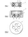
- the throttle insert 1 made of elastomeric material shown in a sectional side view in FIG. 1 has a central opening forming a flow channel 2 and is essentially ring-shaped and symmetrical to a plane 3 lying perpendicular to its opening. On its two end faces, the throttle insert 1 has an annular groove 4 which is concentric with the flow channel 2.
- the wall of the flow channel 2 of the throttle insert 1 is curved in a circular arc, with the result that the inside diameter of the barrel-type flow channel 2 increases continuously on both sides from the outside inwards.
- the transitions from the end ring grooves 4 to the flow channel 2 each form control lips 5 which have a substantially wedge-shaped cross section. Your wedge angle is preferably between 35 and 50 °.
- the outer sides of the two regulating lips 5 are each designed to correspond to the surface of a truncated cone, which extends to the bottom of the respective annular groove 4.
- the throttle insert 1 is also constructed to be rotationally symmetrical. Its overall height is low in relation to the outside diameter. It is approximately 1/4 to 3/4, preferably 1/3 to 1/2 of the outer diameter and is in particular in the size range of the diameter of the flow channel 2.
- the outer edges of the grooves 4 preferably project beyond the control lips 5 in the axial direction.
- the throttle insert 1 shown in a sectional side view in FIG. 1 is assigned a support ring 6, which is shown in a sectional side view in FIG. 2.
- This support ring 6 is dimensioned and designed such that it supports the throttle insert 1 both on the discharge side and preferably radially. It has a support shoulder 7 which is essentially adapted to the outflow-side annular groove 4 of the throttle insert 1 and when the throttle insert 1 is inserted into the support ring 6 (cf. FIG. 4) into this annular groove 4.
- the support shoulder 7 is dimensioned and configured to the abflußseiti g s rule lip 5 leaves the wedge-shaped member in the state un carefullyströmten essentially inde-based e g.
- the support ring 6 has a flow guide element 8 on the outlet side, which in the illustrated embodiment has a base plate provided with four holes 9 is formed, the center of which is closed and divides the water flow coming from the throttle insert with a wedge-shaped or conical elevation.
- the flow guiding element brings about an additional calming of the water flow and also serves for a suitable flow against subsequent jet shaping elements, for example of steel aerators.
- the support ring 6 'shown in FIG. 5 has no such a flow guide element. Rather, this support ring 6 'is provided on the discharge side with a central flow opening 10 which is designed to widen in three stages.
- the support ring 6 or 6 ' forms with the throttle insert 1 inserted in it a compact unit that can be easily in the inflow end of a water fitting, for example the handle of a hand shower (see. Fig. 5) until it stops at one provided Can insert ring shoulder 12, whereupon the water fitting can be connected to a water supply line, for example with a pipe or hose. If this has happened, the water fitting 11 can be supplied with water in the direction of the arrow 13. At low water pressure, the throttle insert 1 forms an obstacle that is comparable in its throttling effect to a perforated disk.
- the throttle insert 1 'shown in sectional side view in FIG. 6 is designed for a flow rate of 2.75 gall / min and differs from the throttle insert 1 shown in FIG. 1 essentially in that the wall of the flow channel 2 in it Longitudinal section not arched, but straight and conical from the outside inwards in opposite directions.
- the inflow and outflow openings of the flow channel 2 are cylindrically chamfered, i.e. the apex, the control lips 5 which are wedge-shaped in cross section, is cut off to form a cylindrical inner surface.
- the inflow and outflow openings of the flow channel 2 are each delimited by an edge 12 which is formed by the respective apex line.
- the lip root d is kept thinner, as a result of which the mobility of the control lips 5 is increased.
Abstract
Description
- Die Erfindung betrifft eine Vorrichtung zur drosselnden Durchflußbegrenzung in Wasser-Armaturen, insbesondere Sanitär-Armaturen, mit einem aus einem elastischen Material bestehenden, sich gegen eine Ringschulter abstützenden Drosseleinsatz, der eine Durchflußdurchbrechung aufweist, die zuflußseitig von einer Regel-Lippe begrenzt ist, die den Eintrittsquerschnitt der Durchflußdurchbrechung in Abhängigkeit von dem Druck des durchfließenden Wassers verkleinert bzw. vergrößert. Eine solche Vorrichtung ist in der DE-A-1650 209 beschrieben.
- Bei den bisher bekannten derartigen Vorrichtungen treten insbesondere im Bereich höherer Förderdrücke unproportionale Regellippen-Verformungen auf. Außerdem sind sie schwierig zu montieren oder aber im Betrieb zu laut.
- Der Erfindung liegt die Aufgabe zugrunde, eine Vorrichtung der eingangs beschriebenen Art dahingehend zu verbessen, daß sie auch im Bereich höherer Förderdrücke den Durchfluß durch eine Rohrleitung gleichmäßig drosselt, und die sich problemlos montieren und austauschen läßt. Außerdem soll eine relativ große Regelöffnung vorhanden sein, die nicht durch kleine im Wasser mitgeführte Schmutzpartikel verstopft werden kann.
- Diese Aufgabe wird durch eine Vorrichtung der eingangs beschriebenen Art gelöst, bei der der Drosseleinsatz zu einer senkrecht zu seiner Durchflußbegrenzung liegenden Ebene symetrisch ausgebildet ist und sowohl zuflußseitig als auch abflußseitig mit einer ringförmigen Regel-Lippe versehen ist. Ein so ausgebildeter Drosseleinsatz bietet zudem den Vorteil, daß er wegen seiner symetrischen Ausbildung nicht falsch eingesetzt werden kann. Wie Versuche gezeigt haben, kann ein derartiger Drosseleinsatz auch geräuscharm ausgebildet werden. Weiterhin wirken die symetrisch gestalteten beidseitigen Regel-Lippen im Betrieb asymetrisch.
- Als besonders vorteilhaft weil besonders geräuscharm und anpassungsfähig arbeitend haben sich Drosseleinsätze erwiesen, die einen Durchflußkanal aufweisen, dessen Durchmesser im unbelasteten Zustand beidseitig vorzugsweise stufenlos von außen nach innen hin zunimmt und darunter insbesondere solche, bei denen die Innenwandung des Durchflußkanales im Längsschnitt bogenförmig, vorzugsweise kreisbogenförmig gewölbt ausgebildet ist, sodaß sich ein balliger oder tonnenförmiger Durchgang ergibt, der an seinen beiden öffnungen von den Regel-Lippen begrenzt ist.
- Bei einer bevorzugten Ausführungsform ist der Drosseleinsatz im wesentlichen rinaförmig ausgebildet und auf beiden Stirnseiten mit einer zum Durchflußkanal konzentrischen Ringnut versehen. Teile der Ringnutwandung bilden dabei die Außenwand der zuflußseitigen bzw. abflußseitigen Regel-Lippe, wobei die Bereiche des Drosseleinsatzes, die die übergänge von den Ringnuten zum Durchflußkanal bilden, vorzugsweise einen Querschnitt aufweisen, der jeweils im wesentlichen dem eines Keiles mit einem Keilwinkel von 35° bis 50° entspricht. Die kleineren Winkel, d.h. der untere Grenzbereich eignet sich mehr für große Bohrungen und große Durchflüsse, wogegen die größeren Keilwinkel eher bei engen Durchflußbohrungen mit entsprechend kleineren Durchflußmengen vorgesehen sind. Keilwinkel von 35 bis 40° erlauben eine große relative Verengung des Durchflußkanales, da die Regel-Lippe stärker umgelegt werden kann.
- Die Außenseite der Regel-Lippen sind vorzugsweise jeweils dem Mantel eines Kegelstumpfes entsprechend ausgebildet, dessen Symetrieachse in Durchflußrichtung verläuft. Dieser Kegelstumpf reicht vorzugsweise bis in den Grund der je- weiligen Ringnut.
- Die der Strömung zugewandte Seite der Regel-Lippen ist vorzugsweise jeweils aus der Querschnittsebene heraus entgegen der Zuströmrichtung um circa 20 bis 40, vorzugsweise 30° geneigt ausgebildet, wodurch eine geräuscharme und rasch auf Druckschwankungen reagierende Drosselung ermöglicht wird. Keilwinkel und Neigung können durch Variation so aufeinander abgestimmt werden, daß gewünschte Kennlinien der Drosselwirkung erfüllt werden.
- Bei einer bevorzugten Ausführungsform ist dem Drosseleinsatz ein Stützring zugeordnet, der den Drosseleinsatz abflußseitig und radial abstützt. Dieser Stützring kann eine Auflageschulter aufweisen, die der abflußseitioen Nut-Profilierung des Drosseleinsatzes im wesentlichen angepaßt ist und in diese hineinragt. Der StützrinQ ist dabei vorzugsweise so ausgebildet, daß seine Auflaaeschulter den keilförmigen Teil der abflußseitigen Regel-Lippe im undurchströmten Zustand im wesentlichen unabgestützt läßt. Zur Strömungsberuhigung und damit verbundener Geräuschdämpfung kann der Stützring abflußseitig wenigstens ein Strömungsleitelement aufweisen, das mit ihm vorzugsweise einstückig ausgebildet ist. Bei einer bevorzugten Ausführungsform ist dieses Strömungsleitelement eine gelochte Grundplatte.
- Der Drosseleinsatz kann mit dem ihm zugeordneten Stützring eine in eine Armatur einsetzbare, beispielsweise einschiebbare Einheit bilden, die als solche auch vom Laien problemlos ohne Zuhilfenahme irgendwelcher Werkzeuge ausgewechselt werden kann. Auch können mehrere, eine verschiedene Drosselwirkung besitzende Drosseleinsätze vorgesehen sein, deren am Stützring zur Anlage kommenden Begrenzung jeweils gleich sind, sodaß sie je nach den vorliegenden Druck- und Strömungsbedingungen auswählbar und in den Stützring einsetzbar sind. Die Außenflächen der-Regel-Lippen schließen mit der Mantelfläche des Drosseleinsatzes einen Winkel von vorzugsweise 50 bis 80° ein.
- Weitere Einzelheiten, Merkmale und Vorteile der Erfindung ergeben sich aus den Ansprüchen und der nachfolgenden Beschreibung bevorzugter Ausführungsformen im Zusammenhang mit der Zeichnung.
- In der Zeichnung zeigen jeweils schematisch:
- Fig. 1 eine geschnittene Seitenansicht eines Drosseleinsatzes,
- Fig. 2 eine geschnittene Seitenansicht eines dem Drosseleinsatz nach Fig. 1 zugeordneten Stützringes,
- Fig. 3 die abflußseitige Ansicht des in Fig. 2 dargestellten Stützringes,
- Fig. 4 eine geschnittene Seitenansicht des in Fig. 1 dargestellten Drosseleinsatzes und des diesen umgebenden Stützringes,
- Fig. 5 den zuflußseitigen Teil einer Wasser-Armatur, in die ein von einem Stützring abflußseitig und radial abgestützter Drosseleinsatz eingesetzt ist, jeweils in geschnittener Seitenansicht und
- Fig. 6 eine geschnittene Seitenanschicht eines Drosseleinsatzes in eine vom Drosseleinsatz nach Fig.l abgewandelten Ausführungsform.
- Der in Fig. 1 in geschnittener Seitenansicht dargestellte Drosseleinsatz 1 aus elastomerem Material weist eine zentrale, einen Durchflußkanal 2 bildende Durchbrechung auf und ist im wesentlichen ringförmig und dabei zu einer senkrecht zu seiner Durchbrechung liegenden Ebene 3 symetrisch ausgebildet. Auf seinen beiden Stirnseiten weist der Drosseleinsatz 1 jeweils eine zum Durchflußkanal 2 konzentrische Ringnut 4 auf. Die Wandung des Durchflußkanales 2 des Drosseleinsatzes 1 ist bei der in Fig. 1 dargestellten Ausführungsform kreisbogenförmig gewölbt ausgebildet, mit der Folge, daß der Innendurchmesser des tonnenartioen Durchflußkanales 2 beidseitig stufenlos von außen nach innen hin zunimmt. Die übergänge von den stirnseitigen Ringnuten 4 zum Durchflußkanal 2 bilden jeweils Regel-Lippen 5, die einen im wesentlichen keilförmigen Querschnitt aufweisen. Ihr Keilwinkel liegt vorzugsweise zwischen 35 und 50°. Wie dies aus Fig. 1 deutlich hervorgeht, sind die Außenseiten der beiden Regel- Lippen 5 jeweils dem Mantel eines Kegelstumpfes entsprechend ausgebildet, der bis zum Grund der jeweiligen Ringnut 4 reicht. Dabei ist der Drosseleinsatz 1 auch rotationssymetrisch aufgebaut. Seine Bauhöhe ist im Verhältnis zum Außendurchmesser gering. Sie beträgt etwa 1/4 bis 3/4, vorzugsweise 1/3 bis 1/2 des Außendurchmessers und liegt insbesondere im Größenbereich des Durchmessers des Durchflußkanales 2. Vorzugsweise überragen die Außenränder der Nuten 4 die Regel-Lippen 5 in axialer Richtung.
- Dem in Fig. 1 in geschnittener Seitenansicht dargestellten Drosseleinsatz 1 ist ein Stützring 6 zugeordnet, der in Fig. 2 in geschnittener Seitenansicht dargestellt ist.
- Dieser Stützring 6 ist so bemessen und ausgebildet, daß er den Drosseleinsatz 1 sowohl abflußseitig als auch vorzugsweise radial abstützt. Er weist eine Auflageschulter 7 auf, die der abflußseitigen Ringnut 4 des Drosseleinsatzes 1 im wesentlichen angepaßt ist und dann, wenn der Drosseleinsatz 1 in den Stützring 6 eingesetzt ist (vgl. Fig. 4) in diese Ringnut 4 ragt. Die Auflageschulter 7 ist dabei so bemessen und ausgebildet, daß sie den keilförmigen Teil der abflußseitigen Regel-Lippe 5 im undurchströmten Zustand im wesentlichen unabge-stützt läßt.
- Der Stützring 6 weist abflußseitig ein Strömungsleitelement 8 auf, das bei der dargestellten Ausführungsform von einer mit vier Löchern 9 versehenen Grundplatte gebildet wird, deren Zentrum verschlossen ist und den aus dem Drosseleinsatz kommenden Wasserstrom mit einer keilförmigen bzw. kegelförmigen Erhebung teilt. Das Strömungsleitelement bewirkt eine zusätzliche Beruhigung des Wasserstromes und dient auch zur geeigneten Anströmung nachfolgender Strahlformungselemente, z.B. von Stahlbelüftern. Der in Fig. 5 dargestellte Stützring 6' weist kein derartiges Strömungsleitelement auf. Dieser Stützring 6' ist vielmehr abflußseitig mit einer zentralen, sich dreistufig erweiternd ausgebildeten Durchflußöffnung 10 versehen.
- Der Stützring 6 bzw. 6' bildet mit dem in ihn eingesetzten Drosseleinsatz 1 eine kompakte Einheit, die sich problemlos in das zuflußseitige Ende einer Wasser-Armatur, beispielsweise den Griff einer Handbrause (vgl. Fig. 5) bis zum Anschlag an eine dort vorgesehene Ringschulter 12 einschieben läßt, woraufhin die Wasser-Armatur mit einer Wasser-Zuführleitung, beispielsweise mit einem Rohr oder Schlauch verbunden werden kann. Ist dies geschehen, so kann der Wasser-Armatur 11 Wasser in Richtung des Pfeiles 13 zugeführt werden. Bei geringem Wasserdruck bildet dabei der Drosseleinsatz 1 ein Hindernis, das in seiner Drosselwirkung mit einer Lochscheibe vergleichbar ist. Nimmt der Wasserdruck zu, so hat dies zur Folge, daß die zuflußseitige Regel-Lippe 5 des Drosseleinsatzes 1 unter dem Druck des durchströmenden Wassers nach innen gezogen, d.h. so verformt wird, daß sie den Eintrittsquerschnitt des Durchflußkanales 2 mehr oder weniger stark, d.h. in Abhängigkeit vom jeweilgen Wasserdruck verkleinert. Die abflußseitge Regel-Lippe 5 des Drosseleinsatzes 1 wird dagegen bei zunehmendem Wasserdruck mehr oder weniger stark nach außen gebogen und bildet eine elastische weiche Begrenzung, so daß sich das den Drosseleinsatz 1 verlassende Wasser ohne besondere Geräuschentwicklung entspannen kann.
- Der in Fig. 6 in geschnittener Seitenansicht dargestellte Drosseleinsatz 1' ist für eine Durchflußmenge von 2,75 gall/ min ausgelegt und unterscheidet sich von dem in der Fig. 1 dargestellten Drosseleinsatz 1 im wesentlichen dadurch, daß bei ihm die Wandung des Durchflußkanales 2 im Längsschnitt nicht bogenförmig, sondern von außen nach innen hin geradlinig gegenläufig konisch verläuft.
- Bei der Ausführungsform nach Fig. 1 sind die Einfluß- und Ausflußöffnungen des Durchflußkanales 2 zylindrisch angefast, d.h. der Scheitel, der im Querschnitt keilförmigen Regel-Lippen 5 ist unter Bildung einer zylindrischen Innenfläche abgeschnitten. Bei der in Fig. 6 dargestellten Ausführungsform sind dagegen die Einfluß- und Ausflußöffnungen des Durchflußkanales 2 jeweils von einer Kante 12 begrenzt, die von der jeweiligen Scheitellinie gebildet wird.
- Bei der Ausführungsform nach Fig. 6 ist die Lippenwurzel d dünner gehalten, wodurch die Beweglichkeit der Regel-Lippen 5 erhöht wird.
Claims (10)
Priority Applications (1)
| Application Number | Priority Date | Filing Date | Title |
|---|---|---|---|
| AT85114595T ATE35026T1 (de) | 1984-11-22 | 1985-11-16 | Vorrichtung zur drosselnden durchflussbegrenzung in wasser-armaturen. |
Applications Claiming Priority (2)
| Application Number | Priority Date | Filing Date | Title |
|---|---|---|---|
| DE3442495 | 1984-11-22 | ||
| DE19843442495 DE3442495A1 (de) | 1984-11-22 | 1984-11-22 | Vorrichtung zur drosselnden durchflussbegrenzung in wasser-armaturen |
Publications (2)
| Publication Number | Publication Date |
|---|---|
| EP0182327A1 true EP0182327A1 (de) | 1986-05-28 |
| EP0182327B1 EP0182327B1 (de) | 1988-06-08 |
Family
ID=6250819
Family Applications (1)
| Application Number | Title | Priority Date | Filing Date |
|---|---|---|---|
| EP19850114595 Expired EP0182327B1 (de) | 1984-11-22 | 1985-11-16 | Vorrichtung zur drosselnden Durchflussbegrenzung in Wasser-Armaturen |
Country Status (4)
| Country | Link |
|---|---|
| US (1) | US4667700A (de) |
| EP (1) | EP0182327B1 (de) |
| AT (1) | ATE35026T1 (de) |
| DE (2) | DE3442495A1 (de) |
Families Citing this family (22)
| Publication number | Priority date | Publication date | Assignee | Title |
|---|---|---|---|---|
| US4940165A (en) * | 1988-04-08 | 1990-07-10 | The Cornelius Company | Method of and dispensing head for increased carbonation |
| US4938259A (en) * | 1989-01-18 | 1990-07-03 | Vernay Laboratories, Inc. | Fluid flow controller |
| US5027861A (en) * | 1989-03-07 | 1991-07-02 | Huron Products Corporation | Flow control fitting enabling high flow rates |
| US4986312A (en) * | 1989-03-07 | 1991-01-22 | Huron Products Corporation | Flow control device |
| US5038976A (en) * | 1989-11-08 | 1991-08-13 | Imi Cornelius Inc. | Method of and dispensing head for increased carbonation |
| US5154394A (en) * | 1991-06-17 | 1992-10-13 | Emerson Electric Co. | Solenoid operated valve with improved flow control means |
| US6299128B1 (en) | 1998-07-31 | 2001-10-09 | Zurn Industries, Inc. | Diaphragm orifice for flushometer |
| DE10220287B4 (de) | 2002-05-07 | 2004-09-16 | Dieter Wildfang Gmbh | Durchflußmengenregler |
| US7306170B1 (en) * | 2003-06-02 | 2007-12-11 | Casino Advisory Services, Llc | Lawn sprinkler flow control device and tool therefor |
| DE102004058302A1 (de) * | 2004-09-17 | 2006-03-23 | Bosch Rexroth Aktiengesellschaft | Dichtbuchse, hydraulisches Gerät und Rückschlagventil |
| US20080092969A1 (en) * | 2006-08-07 | 2008-04-24 | Diperna Paul Mario | Variable flow reshapable flow restrictor apparatus and related methods |
| US7543763B1 (en) * | 2007-08-16 | 2009-06-09 | Alex Wu | Water volume control device for shower head |
| US8986253B2 (en) | 2008-01-25 | 2015-03-24 | Tandem Diabetes Care, Inc. | Two chamber pumps and related methods |
| US8056582B2 (en) * | 2008-08-08 | 2011-11-15 | Tandem Diabetes Care, Inc. | System of stepped flow rate regulation using compressible members |
| US8408421B2 (en) | 2008-09-16 | 2013-04-02 | Tandem Diabetes Care, Inc. | Flow regulating stopcocks and related methods |
| US8650937B2 (en) | 2008-09-19 | 2014-02-18 | Tandem Diabetes Care, Inc. | Solute concentration measurement device and related methods |
| EP2724739B1 (de) | 2009-07-30 | 2015-07-01 | Tandem Diabetes Care, Inc. | Tragbares Infusionspumpensystem |
| US9180242B2 (en) | 2012-05-17 | 2015-11-10 | Tandem Diabetes Care, Inc. | Methods and devices for multiple fluid transfer |
| US9173998B2 (en) | 2013-03-14 | 2015-11-03 | Tandem Diabetes Care, Inc. | System and method for detecting occlusions in an infusion pump |
| US9933792B2 (en) * | 2015-03-23 | 2018-04-03 | Lancer Corporation | Method and apparatus for flow regulation |
| TWM512039U (zh) * | 2015-07-22 | 2015-11-11 | Long Tai Copper Corp | 恆流水波器 |
| US10359787B2 (en) * | 2017-10-11 | 2019-07-23 | Pao-Tang Chen | Two-way flow control valve |
Citations (3)
| Publication number | Priority date | Publication date | Assignee | Title |
|---|---|---|---|---|
| US2454929A (en) * | 1944-07-17 | 1948-11-30 | Dole Valve Co | Flow control |
| US2775984A (en) * | 1953-10-30 | 1957-01-01 | Dole Valve Co | Flow control structure |
| US4457343A (en) * | 1982-09-20 | 1984-07-03 | Eaton Corporation | Flow washer |
Family Cites Families (16)
| Publication number | Priority date | Publication date | Assignee | Title |
|---|---|---|---|---|
| DE1990117U (de) * | 1968-07-25 | Knebel a Rottger o H G 5860 Iserlohn | Verstellbare Drosseh ornchtung | |
| US2409294A (en) * | 1943-11-15 | 1946-10-15 | Carter Carburetor Corp | Passage plug |
| US2593315A (en) * | 1946-10-31 | 1952-04-15 | Dole Valve Co | Flow control device |
| US2728355A (en) * | 1953-10-30 | 1955-12-27 | Dole Valve Co | By-pass flow washer |
| US2936788A (en) * | 1955-04-26 | 1960-05-17 | Dole Valve Co | Flow control system |
| US2960109A (en) * | 1957-01-07 | 1960-11-15 | Gen Controls Co | Flow regulator |
| US2878836A (en) * | 1957-05-13 | 1959-03-24 | Scovill Manufacturing Co | Two-piece flow control valve |
| DE1650209A1 (de) * | 1967-08-02 | 1970-09-10 | Stiebel Werke Gmbh & Co Dr | Vorrichtung zur selbsttaetigen Konstanthaltung einer Stroemungsmittel-Durchflussmenge |
| US3586040A (en) * | 1969-11-06 | 1971-06-22 | Machinery Co Const | Valve means |
| US3642031A (en) * | 1970-01-22 | 1972-02-15 | Haws Drinking Faucet Co | Flow control device |
| US4054157A (en) * | 1975-06-20 | 1977-10-18 | Moseley Jr Charles D | Coupling device for pipes having a convex shaped or straight tubular end |
| US4105050A (en) * | 1976-10-20 | 1978-08-08 | Donald W. Hendrickson | Integral flanged elastomeric flow restrictor |
| US4161965A (en) * | 1977-02-25 | 1979-07-24 | Merritt Thurman L | Water-flow control device |
| US4221335A (en) * | 1978-09-01 | 1980-09-09 | Shames Sidney J | Flow controller and support therefor, and flow controller-noise reducer combinations |
| DE2925640A1 (de) * | 1979-06-26 | 1981-01-08 | Grohe Kg Hans | Durchflussmengenregler |
| IL60775A (en) * | 1980-08-06 | 1983-11-30 | Mehoudar Raphael | Irrigation device |
-
1984
- 1984-11-22 DE DE19843442495 patent/DE3442495A1/de not_active Withdrawn
-
1985
- 1985-11-16 AT AT85114595T patent/ATE35026T1/de not_active IP Right Cessation
- 1985-11-16 EP EP19850114595 patent/EP0182327B1/de not_active Expired
- 1985-11-16 DE DE8585114595T patent/DE3563244D1/de not_active Expired
- 1985-11-19 US US06/799,417 patent/US4667700A/en not_active Expired - Fee Related
Patent Citations (3)
| Publication number | Priority date | Publication date | Assignee | Title |
|---|---|---|---|---|
| US2454929A (en) * | 1944-07-17 | 1948-11-30 | Dole Valve Co | Flow control |
| US2775984A (en) * | 1953-10-30 | 1957-01-01 | Dole Valve Co | Flow control structure |
| US4457343A (en) * | 1982-09-20 | 1984-07-03 | Eaton Corporation | Flow washer |
Also Published As
| Publication number | Publication date |
|---|---|
| ATE35026T1 (de) | 1988-06-15 |
| US4667700A (en) | 1987-05-26 |
| DE3563244D1 (en) | 1988-07-14 |
| DE3442495A1 (de) | 1986-05-22 |
| EP0182327B1 (de) | 1988-06-08 |
Similar Documents
| Publication | Publication Date | Title |
|---|---|---|
| EP0182327B1 (de) | Vorrichtung zur drosselnden Durchflussbegrenzung in Wasser-Armaturen | |
| EP1194823B1 (de) | Durchflussmengenregler | |
| EP2536886B1 (de) | Sanitäres einbauelement für wasserauslauf | |
| EP3054058B1 (de) | Sanitäre einsetzeinheit | |
| EP3670767B1 (de) | Sanitäre einsetzeinheit | |
| EP3213803B1 (de) | Filter-anordnung | |
| DE19603393A1 (de) | Durchflußmengenregler oder dergleichen Drossel | |
| DE2050749C3 (de) | Strahlregler für Wasserleitungshähne | |
| DE2513827A1 (de) | Fluessigkeitsauslasshahn | |
| DE2343831A1 (de) | Absperr- und regulierventil | |
| CH619306A5 (en) | Flow limiter for media flowing in conduits | |
| EP1319878B1 (de) | Rückschlagventil | |
| DE2813226C2 (de) | Absperr- und Regelventil | |
| EP3276095A1 (de) | Vorrichtung zum drosseln des spülstroms aus einem sanitären spülkasten, ablaufventil und sanitärer spülkasten mit einer solchen vorrichtung | |
| DE102016015807A1 (de) | Sanitäre Einsetzeinheit | |
| DE3834997C2 (de) | ||
| EP3969975B1 (de) | Durchflussmengenregler und verfahren zur herstellung | |
| EP3208393A1 (de) | Spülstromdrossel | |
| DE10201626A1 (de) | Sperrventil | |
| EP3138969A1 (de) | Ablaufventil mit spülstrom-drosselelement | |
| DE202016104089U1 (de) | Vorrichtung zum Drosseln des Spülstroms aus einem sanitären Spülkasten, Ablaufventil und sanitärer Spülkasten mit einer solchen Vorrichtung | |
| DE10223789B4 (de) | Strahlregler für eine sanitäre Auslaufarmatur | |
| WO2022194789A1 (de) | Druckbegrenzer | |
| DE3010905A1 (de) | Rueckschlagventil | |
| DE202022106246U1 (de) | Sanitäres Einbauteil, Baureihe von sanitären Einbauteilen und korrespondierende Verbindung |
Legal Events
| Date | Code | Title | Description |
|---|---|---|---|
| PUAI | Public reference made under article 153(3) epc to a published international application that has entered the european phase |
Free format text: ORIGINAL CODE: 0009012 |
|
| AK | Designated contracting states |
Kind code of ref document: A1 Designated state(s): AT BE CH DE FR GB IT LI NL SE |
|
| 17P | Request for examination filed |
Effective date: 19861106 |
|
| 17Q | First examination report despatched |
Effective date: 19870319 |
|
| GRAA | (expected) grant |
Free format text: ORIGINAL CODE: 0009210 |
|
| AK | Designated contracting states |
Kind code of ref document: B1 Designated state(s): AT BE CH DE FR GB IT LI NL SE |
|
| PG25 | Lapsed in a contracting state [announced via postgrant information from national office to epo] |
Ref country code: NL Effective date: 19880608 Ref country code: IT Free format text: LAPSE BECAUSE OF FAILURE TO SUBMIT A TRANSLATION OF THE DESCRIPTION OR TO PAY THE FEE WITHIN THE PRESCRIBED TIME-LIMIT;WARNING: LAPSES OF ITALIAN PATENTS WITH EFFECTIVE DATE BEFORE 2007 MAY HAVE OCCURRED AT ANY TIME BEFORE 2007. THE CORRECT EFFECTIVE DATE MAY BE DIFFERENT FROM THE ONE RECORDED. Effective date: 19880608 Ref country code: GB Free format text: LAPSE BECAUSE OF NON-PAYMENT OF DUE FEES Effective date: 19880608 Ref country code: FR Free format text: THE PATENT HAS BEEN ANNULLED BY A DECISION OF A NATIONAL AUTHORITY Effective date: 19880608 Ref country code: BE Effective date: 19880608 |
|
| REF | Corresponds to: |
Ref document number: 35026 Country of ref document: AT Date of ref document: 19880615 Kind code of ref document: T |
|
| PG25 | Lapsed in a contracting state [announced via postgrant information from national office to epo] |
Ref country code: SE Effective date: 19880630 |
|
| REF | Corresponds to: |
Ref document number: 3563244 Country of ref document: DE Date of ref document: 19880714 |
|
| EN | Fr: translation not filed | ||
| NLV1 | Nl: lapsed or annulled due to failure to fulfill the requirements of art. 29p and 29m of the patents act | ||
| PG25 | Lapsed in a contracting state [announced via postgrant information from national office to epo] |
Ref country code: AT Effective date: 19881116 |
|
| PG25 | Lapsed in a contracting state [announced via postgrant information from national office to epo] |
Ref country code: LI Effective date: 19881130 Ref country code: CH Effective date: 19881130 |
|
| GBV | Gb: ep patent (uk) treated as always having been void in accordance with gb section 77(7)/1977 [no translation filed] | ||
| PLBE | No opposition filed within time limit |
Free format text: ORIGINAL CODE: 0009261 |
|
| STAA | Information on the status of an ep patent application or granted ep patent |
Free format text: STATUS: NO OPPOSITION FILED WITHIN TIME LIMIT |
|
| 26N | No opposition filed | ||
| REG | Reference to a national code |
Ref country code: CH Ref legal event code: PL |
|
| PGFP | Annual fee paid to national office [announced via postgrant information from national office to epo] |
Ref country code: DE Payment date: 20020115 Year of fee payment: 17 |
|
| PG25 | Lapsed in a contracting state [announced via postgrant information from national office to epo] |
Ref country code: DE Free format text: LAPSE BECAUSE OF NON-PAYMENT OF DUE FEES Effective date: 20030603 |