EP0180744A2 - Climbing protection ladder - Google Patents
Climbing protection ladder Download PDFInfo
- Publication number
- EP0180744A2 EP0180744A2 EP85111796A EP85111796A EP0180744A2 EP 0180744 A2 EP0180744 A2 EP 0180744A2 EP 85111796 A EP85111796 A EP 85111796A EP 85111796 A EP85111796 A EP 85111796A EP 0180744 A2 EP0180744 A2 EP 0180744A2
- Authority
- EP
- European Patent Office
- Prior art keywords
- rungs
- central
- back web
- climbing protection
- central spar
- Prior art date
- Legal status (The legal status is an assumption and is not a legal conclusion. Google has not performed a legal analysis and makes no representation as to the accuracy of the status listed.)
- Granted
Links
- 230000009194 climbing Effects 0.000 title abstract description 19
- 239000000463 material Substances 0.000 claims description 3
- 230000000630 rising effect Effects 0.000 claims 1
- 238000010276 construction Methods 0.000 abstract 1
- 230000002349 favourable effect Effects 0.000 abstract 1
- 238000004519 manufacturing process Methods 0.000 description 4
- 230000007797 corrosion Effects 0.000 description 2
- 238000005260 corrosion Methods 0.000 description 2
- 230000006378 damage Effects 0.000 description 2
- 238000010521 absorption reaction Methods 0.000 description 1
- 230000000052 comparative effect Effects 0.000 description 1
- 238000005242 forging Methods 0.000 description 1
- 238000009434 installation Methods 0.000 description 1
- ACCDBHBOYZJSDT-UHFFFAOYSA-N n-(4-bromophenyl)-2-fluoroacetamide Chemical compound FCC(=O)NC1=CC=C(Br)C=C1 ACCDBHBOYZJSDT-UHFFFAOYSA-N 0.000 description 1
- 229910001220 stainless steel Inorganic materials 0.000 description 1
- 239000010935 stainless steel Substances 0.000 description 1
- 238000003860 storage Methods 0.000 description 1
- 238000003466 welding Methods 0.000 description 1
Images
Classifications
-
- E—FIXED CONSTRUCTIONS
- E06—DOORS, WINDOWS, SHUTTERS, OR ROLLER BLINDS IN GENERAL; LADDERS
- E06C—LADDERS
- E06C1/00—Ladders in general
- E06C1/02—Ladders in general with rigid longitudinal member or members
- E06C1/38—Special constructions of ladders, e.g. ladders with more or less than two longitudinal members, ladders with movable rungs or other treads, longitudinally-foldable ladders
- E06C1/381—Ladders with rungs or treads attached only to one rigid longitudinal member
-
- E—FIXED CONSTRUCTIONS
- E06—DOORS, WINDOWS, SHUTTERS, OR ROLLER BLINDS IN GENERAL; LADDERS
- E06C—LADDERS
- E06C7/00—Component parts, supporting parts, or accessories
- E06C7/18—Devices for preventing persons from falling
- E06C7/186—Rail or rope for guiding a safety attachment, e.g. a fall arrest system
- E06C7/187—Guiding rail
Definitions
- the invention relates to a climbing protection ladder consisting of a vertical central spar and horizontal rungs, the central spar having a C-shaped cross section with a front longitudinal slot, opposite flat back web and rounded longitudinal edges adjoining it, and the rungs in the region of the back web from the outside to the central spar are attached to this and are pre-angled with their free outer parts.
- Fall arrest ladders of the type in question are intended to protect a user from a possible crash and serious injuries.
- the user has to wear a safety harness with a safety device, which is inserted into the longitudinal slot of the central spar and can be automatically fixed in the central spar.
- the rungs of such climbing protection ladders can be made from single rungs, i.e. H. Rungs, which alternately extend in opposite directions from the central spar, but also consist of double rungs, each extending in both directions.
- the invention has for its object to form a climbing ladder of the type mentioned in such a way that even if relatively large manufacturing tolerances are allowed, a simple yet functionally fully satisfactory rung assembly is possible retrospectively.
- the rungs are provided with an isosceles-trapezoidal recess for the back web, with which they are placed in the area of the rounded longitudinal edges like a rider seat on the central spar and are connected to the central spar by a clamp fastening.
- the invention is based on the knowledge that the inevitable problem of manufacturing tolerances by the in a certain amount of variable rider seat attachment of the rungs to the central spar can best be managed. At the same time, this rider seat attachment leads to an optimal absorption or introduction of the forces occurring when climbing the climbing protection ladder. At the same time, the interior of the central spar remains practically completely free. In any case, the clamp fastening also allows the rungs to be retrofitted without, for example, damage to a previously applied corrosion protection.
- the rungs could easily be designed as forgings, as in the known climbing protection ladder from which the invention is based. According to a preferred embodiment, however, the rungs are bent from profile bar material.
- the clamp attachment could consist of a latching connection, for example with latching lugs which can be latched into latching recesses on the rung and / or on the central strut or back web.
- the clamp fastening consists of rivets which penetrate the back web and the rungs, is safer and sufficiently simple.
- the climbing protection ladder shown in the figures consists of a vertical central spar 1 and horizontal rungs 2.
- Fig. 1 it can be seen that the rungs 2 are designed as double rungs.
- the possible embodiment as single rungs is indicated in FIG. 1 by the dotted line 3.
- the central strut 1 has a C-shaped cross section with a front longitudinal slot 4.
- the back web 5 opposite the longitudinal slot 4 is essentially flat; this does not rule out the fact that it has protruding bulges in the central spar 1, which serve to fix the catching device, not shown.
- a rounded and bulged longitudinal edge 6 connects to the two longitudinal ends of the back web 5.
- the rungs 2 are attached to the central strut 1 in the region of the back web 5 and connected to it. 1 that the rungs 2 are pre-angled with their free outer parts 7, so that the upwardly angled free outer ends 8 lie in the plane of the longitudinal slot 1.
- Fig. 1 it can again be seen that the rungs 2 are provided with an isosceles-trapezoidal chamber 9 for the back web 5. With this chamber 9, the rungs 2 are placed like a rider seat on the central spar 1, in such a way that they only in the area of the! rounded longitudinal edges 6 bear against the central strut 1. In this position they are then connected to the central strut 1 by a clamp 10.
- the rungs 2 are bent from an L-shaped profile bar material.
- the clamp 10 consists of rivets that pass through the back web 5 and the rungs 2. It goes without saying that due to the rider seat-like arrangement of the rungs 2 between the back web 5 and the rungs 2 in the region of the recess 9, a small distance is left to ensure the tolerance compensation.
Landscapes
- Engineering & Computer Science (AREA)
- Mechanical Engineering (AREA)
- Ladders (AREA)
- Polysaccharides And Polysaccharide Derivatives (AREA)
- Medicines Containing Antibodies Or Antigens For Use As Internal Diagnostic Agents (AREA)
- Hybrid Cells (AREA)
Abstract
Eine Steigschutzleiter besteht aus einem vertikalen Mittelholm (1) und aus horizontalen Sprossen (2). Der Mittelholm (1) weist einen C-förmigen Querschnitt mit vorderem Längsschlitz (4), gegenüberliegendem ebenen Rückensteg (5) und an diesen anschließenden gerundeten Längskanten (6) auf. Die Sprossen (2) sind im Bereich des Rückensteges (5) von außen an den Mittelholm (1) angesetzt und mit diesem verbunden. Mit ihren freien Außenteilen (7) sind die Sprossen (2) vorgewinkelt. Bei einer solchen Steigschutzleiter kommt man zu einem herstellungstechnisch und funktionsmäßig günstigeren Aufbau, wenn die Sprossen (2) mit einer gieichschenklig-trapezförmigen Auskammerung (9) für den Rückensteg (5) versehen sind, mit der die Sprossen (2) lediglich im Bereich der gerundeten Längskanten (6) anliegend reitersitzartig auf den Mittelholm (1) aufgesetzt sowie durch eine Klemmbefestigung (10), insbesondere aus Nieten, mit dem Mittelholm (1) verbunden sind.
Description
Die Erfindung betrifft eine Steigschutzleiter, bestehend aus einem vertikalen Mittelholm und aus horizontalen Sprossen, wobei der Mittelholm einen C-förmigen Querschnitt mit vorderem Längsschlitz, gegenüberliegendem ebenen Rückensteg und an diesen anschließenden gerundeten Längskanten aufweist und die Sprossen im Bereich des Rückensteges von außen an den Mittelholm angesetzt mit diesem verbunden sind und mit ihren freien Außenteilen vorgewinkelt sind.The invention relates to a climbing protection ladder consisting of a vertical central spar and horizontal rungs, the central spar having a C-shaped cross section with a front longitudinal slot, opposite flat back web and rounded longitudinal edges adjoining it, and the rungs in the region of the back web from the outside to the central spar are attached to this and are pre-angled with their free outer parts.
Steigschutzleitern der in Rede stehenden Art sollen einen Benutzer vor einem möglichen Absturz und schweren Verletzungen bewahren. Zu diesem Zweck hat der Benutzer einen Auffanggurt mit Fangeinrichtung zu tragen, die in den Längsschlitz des Mittelholmes eingeführt wird und im Mittelholm selbsttätig festsetzbar ist. Die Sprossen solcher Steigschutzleitern können aus Einfachsprossen, d. h. Sprossen, die sich abwechselnd in entgegengesetzten Richtungen vom Mittelholm erstrecken, aber auch aus Doppelsprossen bestehen, die sich jeweils in beiden Richtungen erstrecken.Fall arrest ladders of the type in question are intended to protect a user from a possible crash and serious injuries. For this purpose, the user has to wear a safety harness with a safety device, which is inserted into the longitudinal slot of the central spar and can be automatically fixed in the central spar. The rungs of such climbing protection ladders can be made from single rungs, i.e. H. Rungs, which alternately extend in opposite directions from the central spar, but also consist of double rungs, each extending in both directions.
Bei einer bekannten Steigschutzleiter der genannten Art (Prospekt "FABA Steigschutz" der Firma Fahrleitungsbau GmbH, D - 4300 Essen 12, vom Oktober 1983) sind die Sprossen in flächiger Anlage am Rückensteg mit dem Mittelholm verschweißt. Das ist zunächst in herstellungstechnischer Hinsicht verhältnismäßig aufwendig. Störend ist aber auch, daß die Steigschutzleiter insbesondere im Zuge der Lagerung und des Transportes verhältnismäßig viel Volumen beansprucht. Ein nachträgliches Anschweißen der Sprossen an den Mittelholm, z. B. am Aufstellungsort der Steigschutzleiter ist praktisch nicht möglich; das gilt insbesondere dann, wenn die Steigschutzleiter nicht in Edelstahl ausgeführt ist und nach dem Anschweißen der Sprossen zum Korrosionsschutz noch feuerzuverzinken ist.In the case of a known climbing protection ladder of the type mentioned (brochure "FABA climbing protection" from Fahrleitungsbau GmbH, D - 4300 Essen 12, October 1983), the rungs are welded to the central strut in a flat arrangement on the back web. Initially, this is relatively complex in terms of production technology. But it is also disturbing that the climbing protection ladder, especially in the course of storage and transportation, is relatively large Volume claimed. Subsequent welding of the rungs to the central spar, e.g. B. at the installation site of the climbing protection ladder is practically not possible; this applies in particular if the climbing protection ladder is not made of stainless steel and is still hot-dip galvanized after the rungs have been welded on to prevent corrosion.
Bei anderen, aus der Praxis bekannten Steigschutzleitern hat man die Sprossen den Mittelholm durchsetzend mit Hilfe von Schrauben am Mittelholm fixiert. Das ist aber aufgrund der Mehrteiligkeit der Sprossen in der Fertigung ebenfalls aufwendig. Außerdem wird der Innenquerschnitt des Mittelholms unnötig eingeschränkt, so daß die Fangeinrichtung entsprechend klein ausgelegt bzw. der Gesamtquerschnitt des Mittelholms entsprechend vergrößert werden muß.In the case of other climbing protection ladders known from practice, the rungs, which penetrate the central spar, are fixed to the central spar with the aid of screws. However, due to the multipart nature of the rungs in production, this is also complex. In addition, the inner cross section of the central spar is unnecessarily restricted, so that the safety gear is designed to be correspondingly small or the overall cross section of the central spar must be increased accordingly.
Der Erfindung liegt die Aufgabe zugrunde, eine Steigschutzleiter der eingangs genannten Art so auszubilden, daß auch dann, wenn verhältnismäßig große Herstelltoleranzen zugelassen werden, ohne weiteres nachträglich eine einfache, gleichwohl funktionell voll befriedigende Sprossenmontage möglich ist.The invention has for its object to form a climbing ladder of the type mentioned in such a way that even if relatively large manufacturing tolerances are allowed, a simple yet functionally fully satisfactory rung assembly is possible retrospectively.
Diese Aufgabe wird gemäß der Erfindung dadurch gelöst, daß die Sprossen mit einer gleichschenklig-trapezförmigen Auskammerung für den Rückensteg versehen sind, mit der sie lediglich im Bereich der gerundeten Längskanten anliegend reitersitzartig auf den Mittelholm aufgesetzt und durch eine Klemmbefestigung mit dem Mittelholm verbunden sind.This object is achieved according to the invention in that the rungs are provided with an isosceles-trapezoidal recess for the back web, with which they are placed in the area of the rounded longitudinal edges like a rider seat on the central spar and are connected to the central spar by a clamp fastening.
Die Erfindung geht hierbei von der Erkenntnis aus, daß dem unvermeidbaren Problem der Herstelltoleranzen durch die in einem bestimmten Umfang variable Reitersitzansetzung der Sprossen an den Mittelholm am besten beizukommen ist. Zugleich führt diese Reitersitzansetzung zu einer optimalen Aufnahme bzw. Einleitung der beim Besteigen der Steigschutzleiter auftretenden Kräfte. Gleichzeitig bleibt der Innenraum des Mittelholmes praktisch vollständig frei. Jedenfalls erlaubt die Klemmbefestigung auch nachträgliche Montage der Sprossen, ohne daß beispielsweise ein vorher aufgebrachter Korrosionsschutz beschädigt wird.The invention is based on the knowledge that the inevitable problem of manufacturing tolerances by the in a certain amount of variable rider seat attachment of the rungs to the central spar can best be managed. At the same time, this rider seat attachment leads to an optimal absorption or introduction of the forces occurring when climbing the climbing protection ladder. At the same time, the interior of the central spar remains practically completely free. In any case, the clamp fastening also allows the rungs to be retrofitted without, for example, damage to a previously applied corrosion protection.
Für die weitere Ausgestaltung der erfindungsgemäßen Steigschutzleiter bestehen mehrere Möglichkeiten. So könnten die Sprossen ohne weiteres wie auch bei der bekannten Steigschutzleiter, von der die Erfindung ausgeht, als Schmiedestücke ausgeführt sein. Nach bevorzugter Ausführungsform sind die Sprossen jedoch aus Profilstabmaterial gebogen. Die Klemmbefestigung könnte aus einer Rastverbindung, beispielsweise mit in Rastausnehmungen einrastbaren Rastnasen an der Sprosse und/oder am Mittelholm bzw. Rückensteg bestehen. Sicherer und hinreichend einfach ist jedoch eine bevorzugte Ausführungsform, bei der die Klemmbefestigung aus Nieten besteht, die den Rückensteg und die Sprossen durchsetzen.There are several options for the further configuration of the climbing protection ladder according to the invention. Thus, the rungs could easily be designed as forgings, as in the known climbing protection ladder from which the invention is based. According to a preferred embodiment, however, the rungs are bent from profile bar material. The clamp attachment could consist of a latching connection, for example with latching lugs which can be latched into latching recesses on the rung and / or on the central strut or back web. However, a preferred embodiment, in which the clamp fastening consists of rivets which penetrate the back web and the rungs, is safer and sufficiently simple.
Im folgenden wird ein Ausführungsbeispiel der Erfindung anhand der beiliegenden Zeichnung erläutert; es zeigen
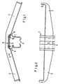
- Fig. 1 eine Aufsicht auf eine Steigschutzleiter und
- Fig. 2 eine Vorderansicht eines Teils der Steigschutzleiter nach Fig. 1.
- Fig. 1 is a plan view of a climbing protection ladder and
- FIG. 2 shows a front view of part of the climbing protection ladder according to FIG. 1.
Die in den Figuren dargestellte Steigschutzleiter besteht aus einem vertikalen Mittelholm 1 und aus horizontalen Sprossen 2 In Fig. 1 erkennt man, daß die Sprossen 2 als Doppelsprossen ausgeführt sind. Die mögliche Ausführungsform als Einfachsprossen ist in Fig. 1 durch die punktierte Linie 3 angedeutet.The climbing protection ladder shown in the figures consists of a vertical central spar 1 and
Der Mittelholm 1 weist einen C-förmigen Querschnitt mit einem vorderen Längsschlitz 4 auf. Der dem Längsschlitz 4 gegenüberliegende Rückensteg 5 ist im wesentlichen eben ausgebildet; das schließt nicht aus, daß er in den Mittelholm 1 vorkragende Ausbauchungen aufweist, die dem Festsetzen der nicht dargestellten Fangeinrichtung dienen. An den beiden Längsenden des Rückensteges 5 schließt jedenfalls jeweils eine gerundete und ausgebauchte Längskante 6 an. Die Sprossen 2 sind im Bereich des Rückensteges 5 von außen an den Mittelholm 1 angesetzt und mit diesem verbunden. Im übrigen erkennt man insbesondere aus Fig. 1, daß die Sprossen 2 mit ihren freien Außenteilen 7 vorgewinkelt sind, so daß die nach oben abgewinkelten freien Außenenden 8 in der Ebene des Längsschlitzes 1 liegen.The central strut 1 has a C-shaped cross section with a front
Aus Fig. 1 entnimmt man wiederum, daß die Sprossen 2 mit einer gleichschenklig-trapezförmigen Auskammerung 9 für den Rückensteg 5 versehen sind. Mit dieser Auskammerung 9 sind die Sprossen 2 reitersitzartig auf den Mittelholm 1 aufgesetzt, und zwar derart, daß sie lediglich im Bereich der ge- ! rundeten Längskanten 6 am Mittelholm 1 anliegen. In dieser Stellung sind sie dann durch eine Klemmbefestigung 10 mit dem Mittelholm 1 verbunden.From Fig. 1 it can again be seen that the
Wie man aus einer vergleichenden Betrachtung der beiden Figuren entnimmt, sind die Sprossen 2 aus einem L-förmigen Profilstabmaterial gebogen. Die Klemmbefestigung 10 besteht aus Nieten, die den Rückensteg 5 und die Sprossen 2 durchsetzen. Es versteht sich von selbst, daß aufgrund der reitersitzartigen Anordnung der Sprossen 2 zwischen dem Rückensteg 5 und den Sprossen 2 im Bereich der Auskammerung 9 ein geringer Abstand belassen ist, um den Toleranzausgleich sicherzustellen.As can be seen from a comparative examination of the two figures, the
Claims (3)
Priority Applications (1)
| Application Number | Priority Date | Filing Date | Title |
|---|---|---|---|
| AT85111796T ATE36028T1 (en) | 1984-11-07 | 1985-09-18 | CLIMBING LADDER. |
Applications Claiming Priority (2)
| Application Number | Priority Date | Filing Date | Title |
|---|---|---|---|
| DE19843440549 DE3440549A1 (en) | 1984-11-07 | 1984-11-07 | RISING PROTECTION LADDER |
| DE3440549 | 1984-11-07 |
Publications (3)
| Publication Number | Publication Date |
|---|---|
| EP0180744A2 true EP0180744A2 (en) | 1986-05-14 |
| EP0180744A3 EP0180744A3 (en) | 1987-04-29 |
| EP0180744B1 EP0180744B1 (en) | 1988-07-27 |
Family
ID=6249638
Family Applications (1)
| Application Number | Title | Priority Date | Filing Date |
|---|---|---|---|
| EP85111796A Expired EP0180744B1 (en) | 1984-11-07 | 1985-09-18 | Climbing protection ladder |
Country Status (8)
| Country | Link |
|---|---|
| US (1) | US4607725A (en) |
| EP (1) | EP0180744B1 (en) |
| CN (1) | CN85107731B (en) |
| AT (1) | ATE36028T1 (en) |
| CA (1) | CA1233798A (en) |
| DE (1) | DE3440549A1 (en) |
| ES (1) | ES296060Y (en) |
| FI (1) | FI78538C (en) |
Cited By (1)
| Publication number | Priority date | Publication date | Assignee | Title |
|---|---|---|---|---|
| ITBS20110091A1 (en) * | 2011-06-22 | 2012-12-23 | Si Al S R L | FALL SCALE AND RELATIVE PRODUCTION METHOD |
Families Citing this family (6)
| Publication number | Priority date | Publication date | Assignee | Title |
|---|---|---|---|---|
| DE8706588U1 (en) * | 1987-05-07 | 1987-08-13 | Soell Industrieschmiede Gmbh, 8670 Hof | ladder |
| DE3819724A1 (en) * | 1988-06-10 | 1989-12-14 | Loh Kg Hailo Werk | METHOD FOR PRODUCING STAGES FOR STEP LADDERS |
| US5069310A (en) * | 1991-03-26 | 1991-12-03 | Houston Industries Incorporated | Insulator climbing support |
| US6305497B1 (en) * | 1999-12-17 | 2001-10-23 | Steve J. Simon | Mast ladder assembly |
| US20120125715A1 (en) * | 2010-11-24 | 2012-05-24 | Ardisam, Inc. | Ergonomic lightweight climbing stick |
| US12516569B2 (en) * | 2021-11-17 | 2026-01-06 | Curt Davidson | Modular ladder with central mast |
Family Cites Families (10)
| Publication number | Priority date | Publication date | Assignee | Title |
|---|---|---|---|---|
| US591418A (en) * | 1897-10-12 | Ladder and duplex step therefor | ||
| US288977A (en) * | 1883-11-27 | Support for swinging or pendent scaffolds | ||
| US973103A (en) * | 1909-02-04 | 1910-10-18 | Edward L Boyd | Ladder. |
| US950182A (en) * | 1909-06-07 | 1910-02-22 | Angus R Mercer | Ceiling-ladder. |
| US2924291A (en) * | 1956-05-14 | 1960-02-09 | Charles W Tunstead | Folding boarding ladder |
| US2957538A (en) * | 1957-11-18 | 1960-10-25 | Blaw Knox Co | Ladder bolt or the like |
| DE2060718B2 (en) * | 1970-12-10 | 1973-08-02 | Fahrleitungsbau Gmbh, 4300 Essen | FALL PROTECTION ON LADDERS OR SIMILAR DEVICES |
| IT949982B (en) * | 1972-03-08 | 1973-06-11 | Cesare Uboldi E Figlie Spa | SAFETY DEVICE TO AVOID THE OPERATOR'S FALLS FROM A LATERAL LADDER |
| NO135072B (en) * | 1975-08-20 | 1976-10-25 | Tor Lynne | |
| US4388983A (en) * | 1982-01-25 | 1983-06-21 | International Telephone And Telegraph Corporation | Lightweight ladder |
-
1984
- 1984-11-07 DE DE19843440549 patent/DE3440549A1/en not_active Withdrawn
-
1985
- 1985-09-18 AT AT85111796T patent/ATE36028T1/en not_active IP Right Cessation
- 1985-09-18 EP EP85111796A patent/EP0180744B1/en not_active Expired
- 1985-10-15 ES ES1985296060U patent/ES296060Y/en not_active Expired
- 1985-10-22 CN CN85107731A patent/CN85107731B/en not_active Expired
- 1985-10-24 US US06/790,963 patent/US4607725A/en not_active Expired - Fee Related
- 1985-10-30 CA CA000494189A patent/CA1233798A/en not_active Expired
- 1985-11-04 FI FI854331A patent/FI78538C/en not_active IP Right Cessation
Cited By (2)
| Publication number | Priority date | Publication date | Assignee | Title |
|---|---|---|---|---|
| ITBS20110091A1 (en) * | 2011-06-22 | 2012-12-23 | Si Al S R L | FALL SCALE AND RELATIVE PRODUCTION METHOD |
| EP2538017A1 (en) * | 2011-06-22 | 2012-12-26 | Si.Al. S.R.L. | Fall prevention ladder and related method of production |
Also Published As
| Publication number | Publication date |
|---|---|
| CA1233798A (en) | 1988-03-08 |
| FI854331L (en) | 1986-05-08 |
| CN85107731B (en) | 1987-03-25 |
| ES296060Y (en) | 1988-01-16 |
| EP0180744A3 (en) | 1987-04-29 |
| ATE36028T1 (en) | 1988-08-15 |
| FI854331A0 (en) | 1985-11-04 |
| FI78538C (en) | 1989-08-10 |
| US4607725A (en) | 1986-08-26 |
| FI78538B (en) | 1989-04-28 |
| CN85107731A (en) | 1986-04-10 |
| EP0180744B1 (en) | 1988-07-27 |
| ES296060U (en) | 1987-07-16 |
| DE3440549A1 (en) | 1986-05-15 |
Similar Documents
| Publication | Publication Date | Title |
|---|---|---|
| DE19638156B4 (en) | Structure for the upper body portion of a vehicle body | |
| DE69600926T2 (en) | Lattice girders for load-bearing railings from suspended platforms | |
| DE19958734B4 (en) | Fall protection system and trolley for use in such a system | |
| EP0180744B1 (en) | Climbing protection ladder | |
| DE29902904U1 (en) | Scaffold side protection | |
| DE29818149U1 (en) | Restraint device for commercial vehicles | |
| DE10146615B4 (en) | fish joint | |
| DE102010015117A1 (en) | Insulating glass window, has bar grill held by hollow profile rails, and screw extending through spacer frame and passing directly into hollow profile rails, where rails are provided with receiving geometries for fitting screws | |
| DE2401461C3 (en) | ||
| EP0290034A2 (en) | Ladder | |
| DE3121019C2 (en) | Roof hook | |
| DE2720414C3 (en) | Fastening device for a guardrail mockery | |
| DE2236101B2 (en) | T profile rail along the free vertical face of a door leaf, a casement or the like | |
| DE19919358C1 (en) | Scaffolding with vertical tube uprights and individual and - or multiple railing tubes has holding devices for fixture of railing tube to tube uprights together with wedge boxes for fixing uprights to wall which is at angle to them | |
| DE202010005075U1 (en) | insulating glass pane | |
| DE2804378B2 (en) | Flange connection between a vehicle axle and the longitudinal spars of a chassis | |
| DE2401461B2 (en) | FASTENING OF RAILING BARS TO RAILING POST | |
| DE8029405U1 (en) | HANGER | |
| DE886659C (en) | Door frame with seal | |
| DE1509978B1 (en) | Outside window sill with Z-shaped cross-section | |
| DE8803762U1 (en) | Fly screen for windows or doors | |
| DE2407317A1 (en) | Fastening for two part ladder - consists of metal strip with Z-shaped ends and acting as guide or support | |
| DE7830866U1 (en) | SNOW GUARDS FOR FIXING ON TIN ROOFS | |
| DE1970171U (en) | FRAME WITH PLUG CONNECTION. | |
| DE102009036329A1 (en) | Device for covering and/or protecting parts of lift system or parts in lift shaft by perforated wall parts, has wall parts having bending running in area of opposite end edges, where bending is formed as connection part |
Legal Events
| Date | Code | Title | Description |
|---|---|---|---|
| PUAI | Public reference made under article 153(3) epc to a published international application that has entered the european phase |
Free format text: ORIGINAL CODE: 0009012 |
|
| AK | Designated contracting states |
Kind code of ref document: A2 Designated state(s): AT BE CH FR GB IT LI NL |
|
| 17P | Request for examination filed |
Effective date: 19861011 |
|
| PUAL | Search report despatched |
Free format text: ORIGINAL CODE: 0009013 |
|
| AK | Designated contracting states |
Kind code of ref document: A3 Designated state(s): AT BE CH FR GB IT LI NL |
|
| 17Q | First examination report despatched |
Effective date: 19880115 |
|
| GRAA | (expected) grant |
Free format text: ORIGINAL CODE: 0009210 |
|
| AK | Designated contracting states |
Kind code of ref document: B1 Designated state(s): AT BE CH FR GB IT LI NL |
|
| REF | Corresponds to: |
Ref document number: 36028 Country of ref document: AT Date of ref document: 19880815 Kind code of ref document: T |
|
| GBT | Gb: translation of ep patent filed (gb section 77(6)(a)/1977) | ||
| ITF | It: translation for a ep patent filed | ||
| ET | Fr: translation filed | ||
| PLBE | No opposition filed within time limit |
Free format text: ORIGINAL CODE: 0009261 |
|
| STAA | Information on the status of an ep patent application or granted ep patent |
Free format text: STATUS: NO OPPOSITION FILED WITHIN TIME LIMIT |
|
| PGFP | Annual fee paid to national office [announced via postgrant information from national office to epo] |
Ref country code: BE Payment date: 19890629 Year of fee payment: 5 |
|
| PGFP | Annual fee paid to national office [announced via postgrant information from national office to epo] |
Ref country code: GB Payment date: 19890630 Year of fee payment: 5 |
|
| 26N | No opposition filed | ||
| PGFP | Annual fee paid to national office [announced via postgrant information from national office to epo] |
Ref country code: AT Payment date: 19890904 Year of fee payment: 5 |
|
| PGFP | Annual fee paid to national office [announced via postgrant information from national office to epo] |
Ref country code: CH Payment date: 19890921 Year of fee payment: 5 |
|
| PGFP | Annual fee paid to national office [announced via postgrant information from national office to epo] |
Ref country code: FR Payment date: 19890927 Year of fee payment: 5 |
|
| ITTA | It: last paid annual fee | ||
| PGFP | Annual fee paid to national office [announced via postgrant information from national office to epo] |
Ref country code: NL Payment date: 19890930 Year of fee payment: 5 |
|
| PG25 | Lapsed in a contracting state [announced via postgrant information from national office to epo] |
Ref country code: GB Effective date: 19900918 Ref country code: AT Effective date: 19900918 |
|
| PG25 | Lapsed in a contracting state [announced via postgrant information from national office to epo] |
Ref country code: LI Effective date: 19900930 Ref country code: CH Effective date: 19900930 Ref country code: BE Effective date: 19900930 |
|
| BERE | Be: lapsed |
Owner name: FAHRLEITUNGSBAU G.M.B.H. Effective date: 19900930 |
|
| PG25 | Lapsed in a contracting state [announced via postgrant information from national office to epo] |
Ref country code: NL Effective date: 19910401 |
|
| GBPC | Gb: european patent ceased through non-payment of renewal fee | ||
| NLV4 | Nl: lapsed or anulled due to non-payment of the annual fee | ||
| PG25 | Lapsed in a contracting state [announced via postgrant information from national office to epo] |
Ref country code: FR Effective date: 19910530 |
|
| REG | Reference to a national code |
Ref country code: CH Ref legal event code: PL |
|
| REG | Reference to a national code |
Ref country code: FR Ref legal event code: ST |