EP0180662B1 - Transducteur de mesure, en particulier pour des applications médicales - Google Patents
Transducteur de mesure, en particulier pour des applications médicales Download PDFInfo
- Publication number
- EP0180662B1 EP0180662B1 EP19840113482 EP84113482A EP0180662B1 EP 0180662 B1 EP0180662 B1 EP 0180662B1 EP 19840113482 EP19840113482 EP 19840113482 EP 84113482 A EP84113482 A EP 84113482A EP 0180662 B1 EP0180662 B1 EP 0180662B1
- Authority
- EP
- European Patent Office
- Prior art keywords
- housing
- sensor chip
- transducer according
- fluid
- substrate
- Prior art date
- Legal status (The legal status is an assumption and is not a legal conclusion. Google has not performed a legal analysis and makes no representation as to the accuracy of the status listed.)
- Expired
Links
Images


Classifications
-
- G—PHYSICS
- G01—MEASURING; TESTING
- G01L—MEASURING FORCE, STRESS, TORQUE, WORK, MECHANICAL POWER, MECHANICAL EFFICIENCY, OR FLUID PRESSURE
- G01L19/00—Details of, or accessories for, apparatus for measuring steady or quasi-steady pressure of a fluent medium insofar as such details or accessories are not special to particular types of pressure gauges
- G01L19/14—Housings
- G01L19/147—Details about the mounting of the sensor to support or covering means
-
- A—HUMAN NECESSITIES
- A61—MEDICAL OR VETERINARY SCIENCE; HYGIENE
- A61B—DIAGNOSIS; SURGERY; IDENTIFICATION
- A61B5/00—Measuring for diagnostic purposes; Identification of persons
- A61B5/02—Detecting, measuring or recording pulse, heart rate, blood pressure or blood flow; Combined pulse/heart-rate/blood pressure determination; Evaluating a cardiovascular condition not otherwise provided for, e.g. using combinations of techniques provided for in this group with electrocardiography or electroauscultation; Heart catheters for measuring blood pressure
- A61B5/021—Measuring pressure in heart or blood vessels
-
- A—HUMAN NECESSITIES
- A61—MEDICAL OR VETERINARY SCIENCE; HYGIENE
- A61B—DIAGNOSIS; SURGERY; IDENTIFICATION
- A61B5/00—Measuring for diagnostic purposes; Identification of persons
- A61B5/03—Detecting, measuring or recording fluid pressure within the body other than blood pressure, e.g. cerebral pressure; Measuring pressure in body tissues or organs
-
- G—PHYSICS
- G01—MEASURING; TESTING
- G01L—MEASURING FORCE, STRESS, TORQUE, WORK, MECHANICAL POWER, MECHANICAL EFFICIENCY, OR FLUID PRESSURE
- G01L19/00—Details of, or accessories for, apparatus for measuring steady or quasi-steady pressure of a fluent medium insofar as such details or accessories are not special to particular types of pressure gauges
- G01L19/0007—Fluidic connecting means
- G01L19/0038—Fluidic connecting means being part of the housing
-
- G—PHYSICS
- G01—MEASURING; TESTING
- G01L—MEASURING FORCE, STRESS, TORQUE, WORK, MECHANICAL POWER, MECHANICAL EFFICIENCY, OR FLUID PRESSURE
- G01L19/00—Details of, or accessories for, apparatus for measuring steady or quasi-steady pressure of a fluent medium insofar as such details or accessories are not special to particular types of pressure gauges
- G01L19/0061—Electrical connection means
- G01L19/0084—Electrical connection means to the outside of the housing
-
- G—PHYSICS
- G01—MEASURING; TESTING
- G01L—MEASURING FORCE, STRESS, TORQUE, WORK, MECHANICAL POWER, MECHANICAL EFFICIENCY, OR FLUID PRESSURE
- G01L19/00—Details of, or accessories for, apparatus for measuring steady or quasi-steady pressure of a fluent medium insofar as such details or accessories are not special to particular types of pressure gauges
- G01L19/14—Housings
- G01L19/142—Multiple part housings
- G01L19/143—Two part housings
-
- G—PHYSICS
- G01—MEASURING; TESTING
- G01L—MEASURING FORCE, STRESS, TORQUE, WORK, MECHANICAL POWER, MECHANICAL EFFICIENCY, OR FLUID PRESSURE
- G01L19/00—Details of, or accessories for, apparatus for measuring steady or quasi-steady pressure of a fluent medium insofar as such details or accessories are not special to particular types of pressure gauges
- G01L19/14—Housings
- G01L19/148—Details about the circuit board integration, e.g. integrated with the diaphragm surface or encapsulation
-
- A—HUMAN NECESSITIES
- A61—MEDICAL OR VETERINARY SCIENCE; HYGIENE
- A61B—DIAGNOSIS; SURGERY; IDENTIFICATION
- A61B2562/00—Details of sensors; Constructional details of sensor housings or probes; Accessories for sensors
- A61B2562/02—Details of sensors specially adapted for in-vivo measurements
Definitions
- the invention relates to a measuring transducer which in particular is useful for medical applications such as extra corporeal measuring of pressure, oxygen content or other physical or chemical properties.
- a transducer of this type as described in the general portion of claim 1 is known from EP-A-0 124 308.
- the pressure sensor of this transducer is carried by an insulating body, which together with a first part of the hosing forms the fluid chamber between them.
- This insulating body also is provided with electrical pins by which the sensor can be connected to corresponding connecting means of an electrical connector plug held by the second part of the housing.
- WO-A-8 203 684 shows a fluid pressure sensor with two pressure ports located aligned with respect to a common axis and a silicon sensor chip clamped between two portions of a housing and therewith being exposed with its two sides to the differential pressure between the two ports. There is no flow of fluid between the two ports.
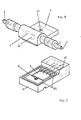
- the housing has a T-shaped configuration consisting of a fluid inlet 1, a fluid outlet 2 and a central box-like part 3 which extends rectangularly with respect to the common axis 4 of inlet 1 and outlet 2.
- Sensor housing 3 has a fluid passage 5 which is aligned with inlet 1 and outlet 2 forming a straightforward fluid channel through which the fluid under measurement can be passed.
- Sensor housing 3 consists (see Figure 2) of a first or bottom part 6 and a second or cover part 7.
- the first part 6 supports the sensor chip 8, a thin film or thick film substrate 9 and electrical connectors 10 which in the shown embodiment are pin connectors but could also be cable connectors or other electrical connecting means to external circuitry.
- the second part 7 of the housing is provided with the cylindrical fluid channel 5 extending along the same axis 4 as inlet 1 and outlet 2 and therewith forming a straight fluid passage.
- the second part 7 of the housing closes two chambers 11 and 12 formed between the two parts 6 and 7 of the housing.
- Chamber 11 communicates with passage 5 and in one of its wall portions the sensing portion of sensor chip 8 is exposed to the fluid entering inlet 1.
- the other chamber 12 is sealed against chamber 11 and contains the thin film or thick film substrate 9 which has provided thereon several adjusting resistors which can be trimmed with respect to their resistance either by laser trimming or sandblasting before the two parts of the housing are fixed together.
- Cover part 7 further has an opening 13 to the outside which may be used as a vent opening or as a filling hole for filling chamber 12 with epoxy resin or other electrically isolating fill protecting the adjusting resistors and the circuitry on film substrate 9, which may also include an amplifier.
- the sensor chip contains a solid state pressure sensor in the form of a silicon diaphragm with integrated strain-sensitive resistors
- bottom portion 6 is provided with an opening 14 communicating with the bottom side of the sensing portion of sensor chip 8 and therewith forming a vent opening for the pressure sensor.
- electrical connectors 10 in the form of connector pins
- a cable might be directly fixed, preferably cast to bottom part 6 of the housing and its wires cast into this bottom part.
- Connector pins 10 are electrically connected by wires 15 to the circuitry on film substrate 9.
- the end portions of the cable wires can be soldered to substrate 9.
- Flexible connecting wires 16 provide electrical connection between the sensor chip 8 and the thin film or thick film substrate 9.
- the configuration of the transducer permits to use the same housing for different types of sensors such as pressure sensor, oxygen sensor or sensors for other physical or chemical properties of a fluid flowing from inlet 1 to outlet 2 of the housing.
- sensors such as pressure sensor, oxygen sensor or sensors for other physical or chemical properties of a fluid flowing from inlet 1 to outlet 2 of the housing.
- a reliable electrical isolation between the electrical circuitry and the flowing fluid is an essential requirement.
- the sensor chip 8 as shown in Figure 5 to 8 is supported by a substrate 17 having about the same coefficient of thermal expansion as the sensor chip 8.
- the sensor chip mainly consists of silicon having a linear expansion coefficient of 30x10-' mm/ mm°C
- this is substrate 17 preferably consists of silicon or FeNiCo (50x10-' mm/mm°C) or Pyrex- glass (33x10-' mm/mm°C) or Ni-Fe 36 (16x10- 7 mm/mm°C). Even a substrate made of stainless steel (130x107 mm/mm°C). might be useful.
- the substrate can also consist of silicon or ceramics. If a metallic substrate is used, the corrosion durability of the metal can be improved by galvanic treatment and heating the substrate in reducing atmosphere.
- Substrate 17 carries sensor chip 8 and in Figure 5 is provided with a passage 18 connecting the lower side of pressure-sensitive silicon diaphragm 19 to space 12. This space 12 via opening 13 (see Figure 2) communicates with the atmosphere. Instead of hole 13 a channel could be provided in parallel to connector pins 10.
- a fluid tight sealing between fluid chamber 11 and chamber 12 is achieved by inserting a silicon rubber ring 20 between those front surfaces of housing parts 6 and 7 which surround fluid chamber 11.
- a ring of silicon rubber adhesive or another type of adhesive may be used for achieving a fluid tight engagement between the two parts of the housing.
- the engaging surfaces 21 of the two parts of the housing are either fixed to each other by an appropriate adhesive or by ultrasonic welding.
- the silicon rubber sheet or adhesive ring 20 provides good electrical isolation of the fluid against the electrical circuitry on film substrate 9 and the connections to the external circuitry.
- connector pads 22 are provided on sensor chip 8 and are by means of flexible and therewith strain-free wires 16 electrically connected to the circuitry on film substrate 9.
- the space 12 above film substrate 9 is filled with a casting resin 23, e.g. epoxy resin for protecting the resistors on substrate 9 and the associated circuitry and connecting wires.
- a casting resin 23 e.g. epoxy resin for protecting the resistors on substrate 9 and the associated circuitry and connecting wires.
- channel 18a in supporting substrate 17a in this case extends downward and ports into hole 14 extending through the base portion 6 of the housing.
- the surface of sensor chip 8 which is exposed to the fluid, i.e. in particular sensing portion 19, is covered by an electrically insulating layer 24 in order to maintain electrical safety of a patient during defibrillation or other electrical treatment.
- the venting channels 14, 18 can also be used for calibrating the sensor at different pressures and/or temperatures.
- the thick film or thin film resistors on film substrate 9 are used for balancing and calibrating the transducer and for this purpose can be changed with respect to their resistance value either by laser trimming or sandblasting.
- the linear expansion matched substrate 17 and the venting openings 14,18 can be deleted.
- the sensor chip 8 then can merely be mounted in a trough-shaped portion of part 6 of the housing.
Landscapes
- Health & Medical Sciences (AREA)
- Physics & Mathematics (AREA)
- Life Sciences & Earth Sciences (AREA)
- General Physics & Mathematics (AREA)
- Medical Informatics (AREA)
- Animal Behavior & Ethology (AREA)
- Pathology (AREA)
- Engineering & Computer Science (AREA)
- Biomedical Technology (AREA)
- Heart & Thoracic Surgery (AREA)
- Cardiology (AREA)
- Molecular Biology (AREA)
- Surgery (AREA)
- Biophysics (AREA)
- General Health & Medical Sciences (AREA)
- Public Health (AREA)
- Veterinary Medicine (AREA)
- Hematology (AREA)
- Vascular Medicine (AREA)
- Physiology (AREA)
- Chemical & Material Sciences (AREA)
- Analytical Chemistry (AREA)
- Measuring Fluid Pressure (AREA)
Claims (15)
Priority Applications (3)
| Application Number | Priority Date | Filing Date | Title |
|---|---|---|---|
| DE8484113482T DE3476695D1 (en) | 1984-11-08 | 1984-11-08 | Measuring transducer, in particular for medical applications |
| EP19840113482 EP0180662B1 (fr) | 1984-11-08 | 1984-11-08 | Transducteur de mesure, en particulier pour des applications médicales |
| CA000494763A CA1252646A (fr) | 1984-11-08 | 1985-11-07 | Transducteur de mesure |
Applications Claiming Priority (1)
| Application Number | Priority Date | Filing Date | Title |
|---|---|---|---|
| EP19840113482 EP0180662B1 (fr) | 1984-11-08 | 1984-11-08 | Transducteur de mesure, en particulier pour des applications médicales |
Publications (2)
| Publication Number | Publication Date |
|---|---|
| EP0180662A1 EP0180662A1 (fr) | 1986-05-14 |
| EP0180662B1 true EP0180662B1 (fr) | 1989-02-08 |
Family
ID=8192275
Family Applications (1)
| Application Number | Title | Priority Date | Filing Date |
|---|---|---|---|
| EP19840113482 Expired EP0180662B1 (fr) | 1984-11-08 | 1984-11-08 | Transducteur de mesure, en particulier pour des applications médicales |
Country Status (3)
| Country | Link |
|---|---|
| EP (1) | EP0180662B1 (fr) |
| CA (1) | CA1252646A (fr) |
| DE (1) | DE3476695D1 (fr) |
Cited By (1)
| Publication number | Priority date | Publication date | Assignee | Title |
|---|---|---|---|---|
| DE102006008752A1 (de) * | 2006-02-24 | 2007-09-06 | Smiths Medical Deutschland Gmbh | Verfahren zum Herstellen einer Fluiddruckmesseinheit und Komponente zum Einsatz in einer Fluiddruckmesseinheit |
Families Citing this family (15)
| Publication number | Priority date | Publication date | Assignee | Title |
|---|---|---|---|---|
| EP0273258B1 (fr) * | 1986-12-22 | 1991-11-21 | Siemens Aktiengesellschaft | Dispositif d'analyse de liquides et procédé d'opération |
| US4850227A (en) * | 1987-12-22 | 1989-07-25 | Delco Electronics Corporation | Pressure sensor and method of fabrication thereof |
| US4825876A (en) * | 1988-02-23 | 1989-05-02 | Abbott Laboratories | Encapsulated blood pressure transducer |
| EP0522567B1 (fr) * | 1991-07-12 | 1996-10-02 | Terumo Kabushiki Kaisha | Convertisseur de pression |
| DE4400941C1 (de) * | 1994-01-14 | 1995-04-20 | Pvb Medizintechnik Gmbh | Druckmeßwandler zur Messung des Druckes einer Flüssigkeit, insbesondere zur invasiven Blutdruckmessung |
| DE69513830T2 (de) * | 1995-10-19 | 2000-04-13 | Hewlett-Packard Gmbh | Blutdruck-Messgerät in Modulbauweise |
| US20070197922A1 (en) * | 2006-02-17 | 2007-08-23 | Honeywell International Inc. | Disposable pressure sensor systems and packages therefor |
| WO2007138208A1 (fr) * | 2006-05-31 | 2007-12-06 | Taema | Dispositif indicateur d'une grandeur physique |
| FR2901875A1 (fr) * | 2006-05-31 | 2007-12-07 | Taema Sa | Dispositif indicateur d'une grandeur physique |
| FR2901874B1 (fr) * | 2006-05-31 | 2008-08-15 | Taema Sa | Dispositif indicateur d'une grandeur physique |
| US7430918B2 (en) * | 2006-12-04 | 2008-10-07 | Honeywell International Inc. | Amplified flow through pressure sensor |
| FR2915799B1 (fr) | 2007-05-03 | 2010-10-01 | Taema | Manometre electronique de mesure de la pression regnant a l'interieur d'un recipient |
| FR2915798B1 (fr) | 2007-05-03 | 2010-04-30 | Taema | Procede de pilotage d'un manometre electronique et manometre correspondant |
| FR2915801B1 (fr) | 2007-05-03 | 2009-07-17 | Taema Sa | Procede de controle d'un lot homogene de bouteilles de fluide sous pression |
| CN107830965A (zh) * | 2017-12-06 | 2018-03-23 | 武汉飞恩微电子有限公司 | 一种汽车碳罐脱附系统用压力传感器 |
Family Cites Families (4)
| Publication number | Priority date | Publication date | Assignee | Title |
|---|---|---|---|---|
| US3592187A (en) * | 1969-09-03 | 1971-07-13 | Univ New York | Blood flow rate - pressure transducer |
| US4411158A (en) * | 1981-04-14 | 1983-10-25 | Ametek, Inc. | Apparatus for sensing the condition of a fluid |
| US4416156A (en) * | 1981-12-23 | 1983-11-22 | Honeywell Inc. | High pressure electrical feedthru |
| US4539998A (en) * | 1983-04-29 | 1985-09-10 | American Hospital Supply Corporation | Pressure transducer assembly |
-
1984
- 1984-11-08 EP EP19840113482 patent/EP0180662B1/fr not_active Expired
- 1984-11-08 DE DE8484113482T patent/DE3476695D1/de not_active Expired
-
1985
- 1985-11-07 CA CA000494763A patent/CA1252646A/fr not_active Expired
Cited By (2)
| Publication number | Priority date | Publication date | Assignee | Title |
|---|---|---|---|---|
| DE102006008752A1 (de) * | 2006-02-24 | 2007-09-06 | Smiths Medical Deutschland Gmbh | Verfahren zum Herstellen einer Fluiddruckmesseinheit und Komponente zum Einsatz in einer Fluiddruckmesseinheit |
| DE102006008752B4 (de) * | 2006-02-24 | 2012-11-29 | Smiths Medical Deutschland Gmbh | Verfahren zum Herstellen einer Komponente einer Fluiddruckmesseinheit, Verfahren zum Herstellen einer Fluiddruckmesseinheit, Komponente zum Einsatz in einer Fluiddruckmesseinheit sowie Fluiddruckmesseinheit |
Also Published As
| Publication number | Publication date |
|---|---|
| DE3476695D1 (en) | 1989-03-16 |
| CA1252646A (fr) | 1989-04-18 |
| EP0180662A1 (fr) | 1986-05-14 |
Similar Documents
| Publication | Publication Date | Title |
|---|---|---|
| EP0180662B1 (fr) | Transducteur de mesure, en particulier pour des applications médicales | |
| US5581038A (en) | Pressure measurement apparatus having a reverse mounted transducer and overpressure guard | |
| JP2965575B2 (ja) | カプセル型圧力測定装置とその製造方法 | |
| US4407296A (en) | Integral hermetic impantable pressure transducer | |
| EP0372773B2 (fr) | Capteur de pression avec un circuit imprimé flexible | |
| US4576181A (en) | Disposable pressure transducer apparatus for medical use | |
| US4960127A (en) | Disposable transducer manifold | |
| EP0614522B1 (fr) | Transducteur de pression amplifie | |
| US4815471A (en) | Catheter assembly | |
| US5184107A (en) | Piezoresistive pressure transducer with a conductive elastomeric seal | |
| US5522267A (en) | Modular diaphragm pressure sensor with peripherally mounted electrical terminals | |
| US4274423A (en) | Catheter tip pressure transducer | |
| US4483196A (en) | Tubular transducer structures | |
| EP0360286A2 (fr) | Transducteur de pression jetable | |
| EP2088414A2 (fr) | Appareil de mesure de la pression différentielle de fluides | |
| JPH02291838A (ja) | ディスポーザブル血圧トランスデューサ | |
| EP0545319B1 (fr) | Capteur de pression à sémi-conducteurs comportant une structure avec deux diaphragmes | |
| US4683894A (en) | Disposable physiological pressure sensing system | |
| JP2001527210A (ja) | 圧力検知装置用の汎用媒体パッケージ | |
| KR20080087119A (ko) | 압력 센서 패키지와, 그 제조 방법, 및 유체 압력 결정방법 | |
| JPS6063437A (ja) | 圧力検出カプセル | |
| WO1986002446A1 (fr) | Transducteur de pression | |
| EP0497534B1 (fr) | Capteur de pression piézorésistif avec un scellement conductif élastomérique | |
| JP2863792B2 (ja) | 血圧トランスジューサの圧力校正装置 | |
| NL8302952A (nl) | Druksensor, geschikt voor het meten van de druk in gedeelten van het levende lichaam. |
Legal Events
| Date | Code | Title | Description |
|---|---|---|---|
| PUAI | Public reference made under article 153(3) epc to a published international application that has entered the european phase |
Free format text: ORIGINAL CODE: 0009012 |
|
| 17P | Request for examination filed |
Effective date: 19851004 |
|
| AK | Designated contracting states |
Kind code of ref document: A1 Designated state(s): BE CH DE FR GB IT LI NL |
|
| 17Q | First examination report despatched |
Effective date: 19870624 |
|
| RAP1 | Party data changed (applicant data changed or rights of an application transferred) |
Owner name: PPG HELLIGE B.V. |
|
| GRAA | (expected) grant |
Free format text: ORIGINAL CODE: 0009210 |
|
| AK | Designated contracting states |
Kind code of ref document: B1 Designated state(s): BE CH DE FR GB IT LI NL |
|
| PG25 | Lapsed in a contracting state [announced via postgrant information from national office to epo] |
Ref country code: IT Free format text: LAPSE BECAUSE OF FAILURE TO SUBMIT A TRANSLATION OF THE DESCRIPTION OR TO PAY THE FEE WITHIN THE PRESCRIBED TIME-LIMIT;WARNING: LAPSES OF ITALIAN PATENTS WITH EFFECTIVE DATE BEFORE 2007 MAY HAVE OCCURRED AT ANY TIME BEFORE 2007. THE CORRECT EFFECTIVE DATE MAY BE DIFFERENT FROM THE ONE RECORDED. Effective date: 19890208 |
|
| REF | Corresponds to: |
Ref document number: 3476695 Country of ref document: DE Date of ref document: 19890316 |
|
| ET | Fr: translation filed | ||
| PG25 | Lapsed in a contracting state [announced via postgrant information from national office to epo] |
Ref country code: GB Effective date: 19891108 |
|
| PG25 | Lapsed in a contracting state [announced via postgrant information from national office to epo] |
Ref country code: BE Effective date: 19891130 |
|
| PLBE | No opposition filed within time limit |
Free format text: ORIGINAL CODE: 0009261 |
|
| STAA | Information on the status of an ep patent application or granted ep patent |
Free format text: STATUS: NO OPPOSITION FILED WITHIN TIME LIMIT |
|
| 26N | No opposition filed | ||
| BERE | Be: lapsed |
Owner name: PPG HELLIGE B.V. Effective date: 19891130 |
|
| GBPC | Gb: european patent ceased through non-payment of renewal fee | ||
| PG25 | Lapsed in a contracting state [announced via postgrant information from national office to epo] |
Ref country code: FR Effective date: 19900731 |
|
| REG | Reference to a national code |
Ref country code: FR Ref legal event code: ST |
|
| PGFP | Annual fee paid to national office [announced via postgrant information from national office to epo] |
Ref country code: NL Payment date: 19901130 Year of fee payment: 7 |
|
| PGFP | Annual fee paid to national office [announced via postgrant information from national office to epo] |
Ref country code: CH Payment date: 19901204 Year of fee payment: 7 |
|
| PGFP | Annual fee paid to national office [announced via postgrant information from national office to epo] |
Ref country code: DE Payment date: 19910131 Year of fee payment: 7 |
|
| PG25 | Lapsed in a contracting state [announced via postgrant information from national office to epo] |
Ref country code: LI Effective date: 19911130 Ref country code: CH Effective date: 19911130 |
|
| PG25 | Lapsed in a contracting state [announced via postgrant information from national office to epo] |
Ref country code: NL Effective date: 19920601 |
|
| NLV4 | Nl: lapsed or anulled due to non-payment of the annual fee | ||
| REG | Reference to a national code |
Ref country code: CH Ref legal event code: PL |
|
| PG25 | Lapsed in a contracting state [announced via postgrant information from national office to epo] |
Ref country code: DE Effective date: 19920801 |