EP0180417B1 - Pulsierende Verbrennungseinrichtung - Google Patents
Pulsierende Verbrennungseinrichtung Download PDFInfo
- Publication number
- EP0180417B1 EP0180417B1 EP85307691A EP85307691A EP0180417B1 EP 0180417 B1 EP0180417 B1 EP 0180417B1 EP 85307691 A EP85307691 A EP 85307691A EP 85307691 A EP85307691 A EP 85307691A EP 0180417 B1 EP0180417 B1 EP 0180417B1
- Authority
- EP
- European Patent Office
- Prior art keywords
- combustion
- chamber
- pulsing
- combustible mixture
- combustion chamber
- Prior art date
- Legal status (The legal status is an assumption and is not a legal conclusion. Google has not performed a legal analysis and makes no representation as to the accuracy of the status listed.)
- Expired
Links
- 238000002485 combustion reaction Methods 0.000 title claims description 205
- 238000007667 floating Methods 0.000 claims description 95
- 239000000203 mixture Substances 0.000 claims description 87
- 239000007789 gas Substances 0.000 claims description 47
- XLYOFNOQVPJJNP-UHFFFAOYSA-N water Substances O XLYOFNOQVPJJNP-UHFFFAOYSA-N 0.000 claims description 32
- 239000000567 combustion gas Substances 0.000 claims description 22
- 239000000446 fuel Substances 0.000 claims description 19
- 238000004891 communication Methods 0.000 claims description 14
- 238000002156 mixing Methods 0.000 claims description 11
- 239000002737 fuel gas Substances 0.000 claims description 6
- 239000008246 gaseous mixture Substances 0.000 claims description 5
- 230000002093 peripheral effect Effects 0.000 claims description 4
- 238000010438 heat treatment Methods 0.000 description 29
- 239000012530 fluid Substances 0.000 description 11
- 230000009471 action Effects 0.000 description 6
- 239000007788 liquid Substances 0.000 description 6
- VNWKTOKETHGBQD-UHFFFAOYSA-N methane Chemical compound C VNWKTOKETHGBQD-UHFFFAOYSA-N 0.000 description 6
- ATUOYWHBWRKTHZ-UHFFFAOYSA-N Propane Chemical compound CCC ATUOYWHBWRKTHZ-UHFFFAOYSA-N 0.000 description 4
- 238000000034 method Methods 0.000 description 4
- 230000008569 process Effects 0.000 description 4
- 239000007787 solid Substances 0.000 description 4
- 230000003247 decreasing effect Effects 0.000 description 3
- 239000000463 material Substances 0.000 description 3
- 238000003466 welding Methods 0.000 description 3
- 235000009781 Myrtillocactus geometrizans Nutrition 0.000 description 2
- 240000009125 Myrtillocactus geometrizans Species 0.000 description 2
- 230000007423 decrease Effects 0.000 description 2
- 238000001914 filtration Methods 0.000 description 2
- 239000002184 metal Substances 0.000 description 2
- 239000003345 natural gas Substances 0.000 description 2
- 239000001294 propane Substances 0.000 description 2
- 238000005201 scrubbing Methods 0.000 description 2
- 238000007789 sealing Methods 0.000 description 2
- 238000011144 upstream manufacturing Methods 0.000 description 2
- OTMSDBZUPAUEDD-UHFFFAOYSA-N Ethane Chemical compound CC OTMSDBZUPAUEDD-UHFFFAOYSA-N 0.000 description 1
- 229910000831 Steel Inorganic materials 0.000 description 1
- 230000002378 acidificating effect Effects 0.000 description 1
- 230000033228 biological regulation Effects 0.000 description 1
- 238000001311 chemical methods and process Methods 0.000 description 1
- 238000009833 condensation Methods 0.000 description 1
- 230000005494 condensation Effects 0.000 description 1
- 238000010276 construction Methods 0.000 description 1
- 238000010411 cooking Methods 0.000 description 1
- 230000001351 cycling effect Effects 0.000 description 1
- 230000000994 depressogenic effect Effects 0.000 description 1
- 239000003344 environmental pollutant Substances 0.000 description 1
- 229930195733 hydrocarbon Natural products 0.000 description 1
- 150000002430 hydrocarbons Chemical class 0.000 description 1
- 238000005461 lubrication Methods 0.000 description 1
- 230000007246 mechanism Effects 0.000 description 1
- 231100000719 pollutant Toxicity 0.000 description 1
- 229920001084 poly(chloroprene) Polymers 0.000 description 1
- 230000002265 prevention Effects 0.000 description 1
- 238000005086 pumping Methods 0.000 description 1
- 230000001105 regulatory effect Effects 0.000 description 1
- 230000000717 retained effect Effects 0.000 description 1
- 230000007480 spreading Effects 0.000 description 1
- 238000003892 spreading Methods 0.000 description 1
- 239000010959 steel Substances 0.000 description 1
- 238000003860 storage Methods 0.000 description 1
Images


Classifications
-
- F—MECHANICAL ENGINEERING; LIGHTING; HEATING; WEAPONS; BLASTING
- F23—COMBUSTION APPARATUS; COMBUSTION PROCESSES
- F23C—METHODS OR APPARATUS FOR COMBUSTION USING FLUID FUEL OR SOLID FUEL SUSPENDED IN A CARRIER GAS OR AIR
- F23C15/00—Apparatus in which combustion takes place in pulses influenced by acoustic resonance in a gas mass
-
- B—PERFORMING OPERATIONS; TRANSPORTING
- B08—CLEANING
- B08B—CLEANING IN GENERAL; PREVENTION OF FOULING IN GENERAL
- B08B3/00—Cleaning by methods involving the use or presence of liquid or steam
- B08B3/02—Cleaning by the force of jets or sprays
-
- B—PERFORMING OPERATIONS; TRANSPORTING
- B08—CLEANING
- B08B—CLEANING IN GENERAL; PREVENTION OF FOULING IN GENERAL
- B08B3/00—Cleaning by methods involving the use or presence of liquid or steam
- B08B3/02—Cleaning by the force of jets or sprays
- B08B3/026—Cleaning by making use of hand-held spray guns; Fluid preparations therefor
-
- F—MECHANICAL ENGINEERING; LIGHTING; HEATING; WEAPONS; BLASTING
- F22—STEAM GENERATION
- F22B—METHODS OF STEAM GENERATION; STEAM BOILERS
- F22B1/00—Methods of steam generation characterised by form of heating method
- F22B1/22—Methods of steam generation characterised by form of heating method using combustion under pressure substantially exceeding atmospheric pressure
-
- F—MECHANICAL ENGINEERING; LIGHTING; HEATING; WEAPONS; BLASTING
- F24—HEATING; RANGES; VENTILATING
- F24H—FLUID HEATERS, e.g. WATER OR AIR HEATERS, HAVING HEAT-GENERATING MEANS, e.g. HEAT PUMPS, IN GENERAL
- F24H1/00—Water heaters, e.g. boilers, continuous-flow heaters or water-storage heaters
- F24H1/22—Water heaters other than continuous-flow or water-storage heaters, e.g. water heaters for central heating
- F24H1/24—Water heaters other than continuous-flow or water-storage heaters, e.g. water heaters for central heating with water mantle surrounding the combustion chamber or chambers
- F24H1/26—Water heaters other than continuous-flow or water-storage heaters, e.g. water heaters for central heating with water mantle surrounding the combustion chamber or chambers the water mantle forming an integral body
- F24H1/28—Water heaters other than continuous-flow or water-storage heaters, e.g. water heaters for central heating with water mantle surrounding the combustion chamber or chambers the water mantle forming an integral body including one or more furnace or fire tubes
-
- G—PHYSICS
- G11—INFORMATION STORAGE
- G11C—STATIC STORES
- G11C11/00—Digital stores characterised by the use of particular electric or magnetic storage elements; Storage elements therefor
- G11C11/21—Digital stores characterised by the use of particular electric or magnetic storage elements; Storage elements therefor using electric elements
- G11C11/34—Digital stores characterised by the use of particular electric or magnetic storage elements; Storage elements therefor using electric elements using semiconductor devices
- G11C11/40—Digital stores characterised by the use of particular electric or magnetic storage elements; Storage elements therefor using electric elements using semiconductor devices using transistors
- G11C11/41—Digital stores characterised by the use of particular electric or magnetic storage elements; Storage elements therefor using electric elements using semiconductor devices using transistors forming static cells with positive feedback, i.e. cells not needing refreshing or charge regeneration, e.g. bistable multivibrator or Schmitt trigger
- G11C11/413—Auxiliary circuits, e.g. for addressing, decoding, driving, writing, sensing, timing or power reduction
- G11C11/417—Auxiliary circuits, e.g. for addressing, decoding, driving, writing, sensing, timing or power reduction for memory cells of the field-effect type
- G11C11/418—Address circuits
-
- H—ELECTRICITY
- H03—ELECTRONIC CIRCUITRY
- H03K—PULSE TECHNIQUE
- H03K19/00—Logic circuits, i.e. having at least two inputs acting on one output; Inverting circuits
- H03K19/0175—Coupling arrangements; Interface arrangements
- H03K19/0185—Coupling arrangements; Interface arrangements using field effect transistors only
- H03K19/018507—Interface arrangements
- H03K19/01855—Interface arrangements synchronous, i.e. using clock signals
-
- B—PERFORMING OPERATIONS; TRANSPORTING
- B08—CLEANING
- B08B—CLEANING IN GENERAL; PREVENTION OF FOULING IN GENERAL
- B08B2230/00—Other cleaning aspects applicable to all B08B range
- B08B2230/01—Cleaning with steam
Definitions
- the invention disclosed herein pertains generally to improvements in combustors or burners and more particularly relates to gas and fuel mixing for such combustors and hot air furnaces having an improved pulsing combustor.
- combustion takes place in an open combustion zone with the combustion gases then passed through a heat exchanger to heat a fluid such as air or water.
- Conventional combustion devices are unsatisfactory since oftentimes combustion is incomplete producing various pollutants and furthermore because the efficiency obtainable from such combustion devices is relatively poor.
- the known burners or combustors used for heating liquids such as water are generally quite massive and consume large amounts of fuel (usually oil or gas). Most presently used burners rely on a continuous flow of the fuel, thus perhaps wasting some of the fuel due to incomplete combustion.
- Combustion devices having an intermittent flow of fuel are known, for example, as in a conventional piston engine or in a pulsing combustor.
- WO-A-82/02242 discloses a pulsing combustion device having the features defined in the pre-characterising part of claim 1.
- the present invention provides a pulsing combustion device comprising: means for defining an elongate combustion chamber having an inlet at one end for a combustible mixture of fuel and combustion air and an unvalved outlet at the opposite end open to the atmosphere for combustion gases: a floating valve member mounted in reciprocation relation within a limiting chamber adjacent said one end of said combustion chamber, said valve member having a first side in communication with said combustion chamber and a second side in communication with a supply of a pressurized combustible mixture and having a plurality of evenly arcuately spaced ports in said valve member said reciprocation of said valve member in said limiting chamber closing and opening communication through said ports between said supply of combustible mixture and said combustion chamber; means for supplying a pressurized combustible mixture of fuel and combustion air to said second side of said floating valve member; means for igniting and combusting said combustible mixture in said combustion chamber to produce pressurized combustion gases, said floating valve member being reciprocated by said pressurized
- a pulsing combustion device comprises a combustion chamber with an inlet for a combustible mixture and an unvalved outlet to the atmosphere for combustion gases.
- a pressurized combustible mixture is supplied to a floating valve with through ports providing controlled communication between the supply of the combustible mixture and the combustion chamber. Reciprocation of the floating valve member increases and decreases the flow of combustible mixture into the combustion chamber.
- the combustible mixture is ignited and burned in the combustion chamber.
- the floating valve is reciprocated in its mounting in the wall of the combustion chamber by the pressure of the pressurized combustible mixture and the pressure of the combustion gases to regulate the flow of the combustible mixture into the combustion chamber.
- EP-A-67223 teaches and claims specific embodiments of my pulsing combustion device and process and specific embodiments of a fluid heating device incorporating my pulsing combustion device. This application teaches and claims further improvements to my pulsing combustion device and its use in water heating and hot air heating applications.
- Heating devices for a wide variety of purposes according to the present invention may use a pulsing combustion device as described either submerged in a fluid or having a flow of fluid, either liquid or gas, encircling the combustion chamber so that the fluid is heated.
- Heat exchange may be enhanced by placement of baffles in and/or downstream of the combustion zone and combustion products may be passed through a wide variety of coil and/or finned heat exchangers.
- the fluid to be heated may be passed through coil and/or finned heat exchangers.
- a particularly suitable combustible mixture supply means and system is described.
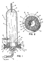
- a known pulsing combustion device 10 includes an elongate combustion chamber shell or burner shell 14 which defines a combustion chamber 15.
- the combustion chamber shell 14 is generally tubular with a length that is considerably greater than its width.
- the combustion chamber shell is preferably circular in cross section, but may of course be square, rectangular or of any other suitable configuration.
- the combustion chamber 15 is closed except for the outlet for combustion gases and the inlet for admitting the combustible mixture.
- the combustible mixture may be supplied by a line 40 through a ball valve chamber 34 by way of a reciprocating floating valve 20.
- the ball valve chamber 34 is provided within an end cap 17 disposed at an inlet end of the combustor shell 14.
- the end cap 17 together with the combustor shell 14 define a path of reciprocation for the floating valve 20.
- the combustion gases exit through an open exhaust tube 50 disposed at an exhaust end 18 of the combustor shell 14.
- the ball valve chamber may be deleted or replaced by a suitable conventional check valve.
- the ball valve chamber 34 or the check valve 507 may serve to prevent a flashback of the combustible mixture.
- Any suitable flame arrestor may be used, such as flame arrestor 601 as shown in Fig. 3.
- ball valve chamber 34 and unvalved exhaust tube 50 have diameters which are considerably smaller than the cross-sectional diameter of the burner shell 14.
- the burner shell 14 is substantially closed on each end and has two restricted passageways: the ball valve chamber 34 at the inlet to the combustion chamber 15 and the exhaust tube 50 disposed at the exhaust end 18 of the burner shell 14.
- the burner shell 14, the ball valve chamber 34 and the exhaust tube 50 are all preferably made of a temperature resistant steel or other material which can tolerate the high temperatures generated in the combustion chamber while the combustible mixture is burning.
- a flange 76 is secured, for example, by welding, to the end cap 17 to facilitate the assembly of the end cap 17 with the shell 14.
- a plurality of bolts 74 extend through openings in the flange and are threadably received by corresponding nuts 72 which are secured, as by welding, to the shell 14.
- the end cap 17 is thereby detachably secured to the shell 14 by the nuts 72 and the bolts 74.
- a sealing gasket 78 preferably of neoprene or another gasket material suitable for high temperature use may be preferably disposed between the end cap 17 and a lower end wall of the burner shell 14.
- the floating poppet valve 20 disposed for reciprocal movement in the burner or combustor shell 14 may be generally mushroom-shaped with an open interior or bore 26, as shown in Figs. 1 and 2.
- the floating valve 20 is of integral construction and includes a base 27 having a first diameter and a tube 23 having a reduced diameter with the bore extending through the tube and through a portion of the base.
- a small clearance is provided between a side wall 25 of the base of the floating valve and a side wall 19 of a base portion of the burner shell 14 to allow the combustible mixture to flow therethrough.
- the side wall 19 of the burner shell 14 is disposed between an annular shoulder portion 16 and the end cap 17 of the burner shell 14.
- the floating valve 20 is preferably made of a temperature resistant metal or other suitable material for high temperature use.
- the floating valve 20 is disposed within the combustor shell 14 for reciprocation between the annular shoulder 16 provided on a lower portion of the combustor shell 14 and the cap 17 of the combustor shell 14.
- a corresponding annular shoulder 22 on the base portion of the poppet valve 20 limits movement of the floating valve 20 toward the combustion chamber when the shoulder 22 of the poppet valve contacts the shoulder 16 of the burner shell 14. Movement of the valve 20 away from the combustion chamber is limited by contact of a rear surface 21 of the floating valve 20 with an inside surface 11 of the cap 17 of the combustor shell 14.
- a plurality of ports 24 are disposed around the floating valve 20 beneath the shoulder 22 of the floating valve 20 and provides communication between the bore of the valve and the small clearance between the valve side wall 25 and the side wall 19.
- the ports 24 are preferably arranged substantially parallel to the rear surface 21 of the valve 20 and extend radially from the bore.
- a spark plug 60 extends into the combustion chamber through a threaded bore in the combustor chamber shell 14.
- the spark plug 60 is provided to initially ignite the combustion gases in the shell 14.
- the spark plug 60 is preferably threaded into the combustion chamber shell 14 so as to provide a seal between the spark plug 60 and the combustor shell 14.
- the spark plug 60 is disposed near the floating valve 20 but far enough from the inlet end of the combustion chamber 25 to not interfere with the reciprocation of the floating valve 20.
- the ball check valve provided in the combustible mixture supply line 40 includes a smooth ball 30 arranged to reciprocate toward and away from a rear seat 32 of the ball valve chamber 34.
- the ball 30 is preferably maintained in contact with the rear surface 21 of the floating valve 20.
- the extent of reciprocation of the valve 20 is preferably small with respect to the diameter of the ball 30, so that the ball 30 is held within the chamber 34 by the floating valve 20 during reciprocation.
- the valve seat snugly against the ball 30 when the ball is received on the rear seat 32 so that the valve 20 may maintain a sealing relationship for the ball and seat 32 when the valve is in contact with the end cap 17.
- various arrangements may be provided at a front end of the ball valve 34 such as fingers or a lattice to retain the ball 30 in the ball valve chamber 34.
- the ball check valve during reciprocation assists in the regulation of the flow of combustible mixture into the combustion chamber 15 along with the floating valve 20.
- the ball valve 30 also prevents backfire through the supply line 40 by preventing a flame in the combustion chamber 15 from spreading backwardly into the combustible mixture supply line 40. If desired, additional or different backfire prevention devices, such as a suitable conventional check valve or other type of flame arrestor, could be provided in supply line 40 upstream of the ball valve 34 or instead of the ball valve 34.
- the exhaust tube 50 at the exhaust end 18 of the burner shell 14 has a first end 51 disposed inside the burner shell 14 and a second end 52 disposed outside the burner shell 14.
- the exhaust tube 50 is relatively small in cross-sectional diameter with respect to the burner shell 14.
- the burner shell 14 preferably has a sloping or curving exhaust end surface 12 which slopes inwardly toward the exhaust tube 50 and with the tube 50 preferably ending at, or perhaps extending only slightly through, a central portion of the end surface 12. If the inner end of the exhaust tube 50 protrudes too far into the combustion chamber 15, the efficient operation of the chamber may be interrupted.
- end surface 12 curved or sloping to provide a tornadic action which is believed to cause intense heat and complete combustion of the combustible mixture and therefore a more efficient use of the fuel within the pulsing combustor.
- the exhaust tube 50 may have to be adjusted in size and location to "tune" the exhaust flow from the combustion chamber shell or burner shell 14. By “tuning” the exhaust tube 50, the desired operating characteristics of the burner namely, the number of pulses per minute, the pressure in the combustion chamber 15, the velocity of the gas exhausted and other such factors may be optimized. For example, if the tube diameter is too large, the combustion of the gases may not produce a sufficient pressure to reciprocate the floating valve 20.
- the burner shell 14 is considerably larger in diameter than the exhaust tube 50.
- the appropriately sized exhaust tube 50 is rigidly secured to the combustion chamber 14, preferably by welding.
- the appropriate relative dimensions for the shell 14, the exhaust tube 50 and the floating valve 20 will be readily determined experimentally by one skilled in the art upon reading the present specification. Specifically, in each embodiment, it is recommended that values for all but one of the variables be preselected with the remaining variable sized according to the preferred operation of the device.
- a pressurized combustible mixture is supplied to the bottom of the floating valve through the combustible mixture supply line 40 by way of the ball valve chamber 34.
- the combustible mixture is preferably an air and gas combination with the gas preferably being either natural gas or propane although pure ethane, pure methane or other combustible gases would also suffice.
- Gas and air are mixed through a suitable conventional valving system, from an air compressor, and a source of fuel gas, not illustrated, in a suitable, conventional manner to form the combustible mixture which is supplied to the combustible mixture supply line 40.
- the pressurized combustible mixture initially lifts the ball valve 30 from its seat 32 in the ball valve chamber and since the ball is in contact with the rear surface 21 of the floating valve 20, the floating valve 20 is also lifted so that the combustible mixture can flow around the ball valve 30 into the small clearance between the valve side wall 25 and the side wall 19 of the shell 14.
- the combustible mixture may then flow through the ports 24 into the combustion chamber by way of the bore 26 of the floating valve.
- the combustible mixture exerts a force against the entire rear surface 21 of the floating valve 20 as soon as it is lifted and thereby lifts the floating valve 20 quickly away from the end cap 17 of the burner shell 14. With continued force against the rear surface 21, floating valve 20 continues upwardly being restricted by the shoulder 22 of the floating valve 20 contacting the shoulder 16 of the burner shell 14.
- valve 20 Since the valve 20 floats on a cushion of the combustible mixture, no lubrication of the floating valve is needed and the valve is cooled by the incoming combustible mixture. Note also that unlike the normal poppet valve which is either cam operated or spring loaded, the valve of the present invention is reciprocated by the pressure differential between a pressure in the combustion chamber 15 and a pressure in the combustible mixture supply line 40 and may have the assistance of a spring in some embodiments.
- the combustible mixture then flows between the side wall 19 of the burner shell 14 and the side wall 25 of the floating valve 20.
- the mixture flows around and through the ports 24 in the floating valve 20 and into the open interior 26 thereof.
- the shoulder 22 of the valve 20 is close to or in contact with the shoulder 16 of the burner 14, the combustible mixture is constrained to flow through the ports 24 in the valve 20.
- the combustible mixture then flows out a front bore 26 in the floating valve 20 and flows into a main portion of the burner shell 14.
- the spark plug 60 is fired to initially ignite the mixture. Once the spark plug 60 has initially ignited the combustible mixture the spark plug 60 is no longer utilized. Instead, further ignition of the combustion mixture occurs due to the continuing flame or heat still retained in the combustion chamber 15. When a new charge of combustible mixture is admitted into the combustion chamber 15, the continuing flame ignite the fresh combustion mixture. Thus the combustion, charging and ignition process continues automatically.
- the pressure in the combustion chamber 15 decreases.
- the pressure in the combustion chamber 15 has decreased sufficiently, for example, to an effective pressure below the effective pressure of the combustible mixture in the combustible mixture supply line 40, the pressure of the combustible mixture forces the floating valve 20 upwardly from the cap 17 of the burner shell 14 to repeat the process.
- the valve acts like a differential piston.
- the cross-sectional area of the floating valve 27 upon which the exhaust products force acts is significantly larger than the area upon which the combustible mixture force acts, only the cross-sectional area, of the supply line 40.
- a lower pressure than the pressure in the combustible mixture supply line 40 is required in the combustion chamber 15 before the floating valve 20 is lifted from engagement with the end cap 17 of the burner shell 14.
- the length of reciprocation of the floating valve 20 is desirably smaller than the diameter of the ball valve 30 to ensure that the ball valve 30 stays in the ball valve chamber 34.
- the pressure of the mixture in the line 40 acts on the exposed lower surface of the ball 30 when the ball is seated in the chamber 34 whereas the pressure of the combustion gases effectively acts on the entire cross-sectional area of the floating valve.
- a significantly lower pressure in the combustion chamber than in the supply line will keep the ball seated in the ball check valve.
- the force on the floating valve upper surface will be sufficient to urge the floating valve downwardly away from the surface 16.
- the effective surface area of the floating valve increases with the result that the floating valve is more easily urged downwardly.
- the effective surface area of the floating valve as seen by the combustion mixture is significantly reduced to the cross-sectional area of the supply line 40.
- the combustion gases may now more easily keep the valve 20 and the ball 30 seated in the lowermost position.
- the speed at which the valve travels is increased significantly. That is, the valve moves quickly between its uppermost and lowermost positions because a slight movement of the valve immediately results in a significant increase in the effective area of the dominant force.
- the varying surface area helps maintain the floating valve in the uppermost and lowermost positions and helps to quickly move the floating valve between the positions.
- the valve 20, as shown in Figs. 1 and 2, has a passageway provided in the front face whereas the rear surface 21 is completely closed.
- An upper section of the valve 20 including the bore 26 is defined by an annular portion or tube 23 which is reduced in size with respect to the base portion 27 of the valve.
- the valve is preferably machined from a solid piece of metal.
- the bore 26 extends completely through the upper section and only partially through the base portion 27 of the valve 20.
- the ports 24 extend into the bore 26 to provide a path of flow for the combustible mixture.
- the size and the number of the ports 24 in the poppet valve 20 depends upon the type of fuel used and the pressure at which the combustible mixture is supplied.
- the combustible mixture preferably enters the combustion chamber only through the ports 24 and thus, the valve 20 may serve as a flame holder or flame tube to contain the flame generated by the burning of the combustible mixture.
- Floating valve 20 may suitably reciprocate at up to about 3500 times per minute in the pulse combustion device.
- the frequency of reciprocation may vary and depends upon the relative size of the combustor shell and the exhaust tube 50, the rate of flow of the fuel and air mixture through the floating valve, and the pressure at which the combustible gases are supplied. While variation of physical characteristics and conditions may vary the pulsing rate, generally, for most purposes the frequency of reciprocation of the floating valve will be about 3200 to about 3400 cycles per minute. However, for some purposes it may be desired to have the frequency reciprocation as low as 800 to 900 cycles per minute.
- One preferred embodiment of the present invention has a burner shell which is about 25 cm long with a diameter of about 2.5 cm (i.e., a 10:1 ratio).
- the floating valve is about 1 cm in length and reciprocates through a length of approximately 5 mm.
- the combustible mixture is pressurized to approximately 2.5-3.5 kg/cm2 with an air to propane mixture ratio of about 25 to 1.
- An interior temperature of approximately 925 o C was very quickly developed in the combustion chamber 15 after ignition of the combustible mixture.
- a pumping mechanism may provide the combustible mixture as a series of discrete pressurized pulses at the desired rate of cycling of the floating valve.
- a spring may be provided in a chamber beneath the floating valve to urge the floating valve toward the open position.
- Fig. 3 shows, in simplified somewhat schematic form, an embodiment of a pulse combustion burner according to this invention.
- Combustion chamber, shell 614 defines combustion chamber 615 with end cap 676 at the inlet end.
- Floating valve 620 is a flat plate with peripheral through openings 624 which may be in the form of holes as shown in Fig. 4 or in the form of open slots as shown in Fig. 5.
- Use of the flat plate floating valve 620 avoids problems of the valve binding as may occur with the floating valve configuration shown in Fig. 1.
- Use of the flat plate floating valve also permits operation with less space between the edges of the valve and the inner walls of the chamber in which it reciprocates.
- the through openings 624 direct the combustible gases along the walls of combustion chamber 615 to provide a hollow, high combustion efficiency blue flame.
- This configuration also provides exceptionally high heat transfer through combustion chamber walls 614 due to the proximity of the flame to the heat exchange surface and due to scrubbing action by the combustible gases and flame action along the interior of walls 614 to reduce film heat transfer coefficients.
- through openings may be at right angles to the plane of flat plate 620 or may be angled to direct the gaseous flow therethrough along combustion chamber walls 614. It is readily apparent that flat plate floating valve 620 may be used in any of the embodiments described utilizing ball valve 30 as shown in Fig. 1 or with spring assistance.
- the floating valve preferably the flat plate floating valve, as shown in Fig. 11 is in the form of annular floating valve 628 having through holes 624 and the combustible gas inlet is in the form of a plurality of inlets 641 supplied by gas manifold 642 around a corresponding annular area in the end cap 676.
- the annular structure of the end cap may have a hollow cylindrical portion 677 extending into the combustion chamber with a solid end a short distance into the combustion chamber from the limit of travel of the floating valve and having the ignition means 660 extending therethrough.
- a spark plug or other ignitor may be placed through the solid end of the cylindrical portion of the end cap extending into the combustion chamber. This location for the ignitor provides ignition more evenly to the hollow flame.
- combustion chamber shell 614 has open end 618 open to the atmosphere instead of closed end 18 with small unvalved exhaust tube 50 as shown Fig. 1.
- the embodiment shown in Fig. 3 has constriction baffles 670, 671 and 672 with exhaust ports 680, 681 and 682, respectively.
- the constriction baffles are preferably of conical shape as shown. I have found that two or three constriction baffles within combustion chamber 615 results in cleaner combustion in a smaller combustion chamber with increased heat transfer through combustion chamber shell 614.
- the exhaust ports in the constriction baffles must be tuned for the system geometry in the same manner as described above with respect to exhaust tube 50.
- constriction baffles may be advantageously used with any of the embodiments described, regardless of configuration of the floating valve and with or without restricted exhaust tube 50, as shown in Fig. 1. Generally, 2 to about 6 constriction baffles may be used to achieve improved heat exchange with a more compact burner-heat transfer unit.
- the heat transfer portion may be folded as shown schematically in Fig. 6.
- combustible gas input 740 provides combustible gas to a floating valve assembly, as described, which provides pulsed combustible gas to the combustion chamber 715 where it is combusted.
- the combustion products pass upwardly against constriction baffles 770 and 771 and through exhaust ports 780 and 781, respectively, through exhaust tube 750 to heat exchanger 710 with constriction baffles 772 and 773, and exits by exhaust tube 750.
- any larger diameter tube may be used to convey combustion product gas to heat exchanger 710.
- Heat removal from combustion chamber walls 614 as shown in Figs. 3 and 6, and heat exchanger walls 710, as shown in Fig. 6, may be effected by any suitable means, including those described above.
- Heat exchange liquid coil 630 is shown in Fig. 3 as exemplary of a suitable heat exchanger means.
- Fig. 7 shows one embodiment of a hot water heater of this invention utilizing a pulse combustor of this invention.
- Water tank 810 has water inlet 811 and hot water outlet 812.
- the water tank top 813 may be depressed to provide mounting bracket 814 and outlet water jacket 815.
- Air bleed and safety means 816 is provided in an upper portion of the tank.
- Water drain means 817 may be provided as desired.
- a pulsed combustor of this invention 880 is mounted with its combustion zone 881 in the region of outlet water jacket 815 to provide direct heat transfer through the combustion chamber walls to water being withdrawn through hot water outlet 812.
- Heat transfer zone 882 of combustor 880 extends downwardly into the volume of water and combustion products exhaust tube 850 conveys combustion products for further heat transfer in finned heat transfer means 851 and the exhaust exits from the water heater through exhaust conduit 852 at relatively cool temperatures.
- Control components of the pulsed combustor 880 are schematically shown: spark plug 860 and suitable ignition power supply 861; air supply line 862 and compressor and metering means 863; gas supply line 864 and pressure and metering means 865; mixing means 866 for mixing air and gas and flashback arrestor 867 preventing ignition prior to combustion chamber 881. Any of the floating valve configurations and heat exchanger configurations described may be used in this embodiment.
- the pulse combustor may be in a vertical position extending either downwardly or upwardly in the water tank, or may be in a horizontal position in the water tank.
- Fig. 8 schematically shows one embodiment of a pulse combustor of this invention used in an air heating system.
- Fig. 8 in simplified schematic form, shows air heater 900 wherein an air treatment passage is defined by air treatment duct 930 with cold air entering as shown by arrows 901 and leaving as heated air shown by arrows 902.
- the air to be heated usually return air from an enclosed volume, such as a room, is driven through treatment duct 930 by an upstream blower, not shown, and first passed over heat exchanger 903 and then passed in direct contact with pulse combustor chamber 906 and pulse combustor exhaust manifold 904 and through treatment unit comprising any desired humidification means and filtering means.
- the treatment air blower means, filtering means and humidification means are not shown, but are any such suitable means as conventionally used in warm air furnaces as known to the art. Although shown in a horizontal air passage configuration, the entire assembly may be rotated 90° and operated in either a down-pass or up-pass mode. The pulse combustor will operate in any of these positions.
- combustion air is provided through air intake 941 of combustion air blower 940 where it is pressurized to a pressure in the range 0.875 to 1.75 kPa, preferably in the range 1 to 1.5 kPa .
- the combustion air pressure and flow rate is maintained and regulated by combustion air flow regulator shown generally as 924 in Fig. 8.
- combustion air flow regulator 924 has rod 925 with tapered head 927 which fittingly engages tapered inlet 928.
- Combustion air flow regulator rod 925 is preferably threaded and is readily adjustable through a threaded bore in the T-shaped end of combustion air pressurized conduit 942.
- lock nut 926 is provided to lock combustion air flow regulator rod 925 in desired position and if desired, bearing means may be provided within combustion air pressurized conduit 942 to assure centering of tapered head 927 within tapered inlet 928. It is readily seen that as tapered head 927 is advanced into tapered inlet 928 the flow of pressurized combustion air is decreased and its pressure, assuming a constant speed combustion air blower 940, is increased.
- Combustible fuel gas such as natural gas
- gas supply line 921 is introduced through gas supply line 921 into a mixing chamber downstream from combustion air flow regulator 924.
- gas supply line 921 is a suitable gas pressure controller, as is well known to the art, to provide fuel gas at a pressure of 0.5 to 0.875 kPa and preferably 0.75 to 0.875 kPa.
- High pressure air gas tap 923 is provided to monitor the pressure of combustion air prior to passage through tapered inlet 928 and may be provided with a safety switch which allows a gas valve in gas supply line 921 to open only after desired pressure is reached in combustion air pressurized conduit 942.
- Low pressure combustible mixture tap 922 is provided in combustible gaseous mixture supply line 920 for control purposes. I have found that using the high pressure combustion air supply as described in conjunction with pulse combustor that there has been no tendency for flashback, however, safety codes may require that a spark arrestor be placed in combustible gaseous mixture supply line 920.
- floating valve 915 Due to the low pressure combustible gaseous mixture supplied to floating valve 915, I have found it desirable to provide an enlarged combustible gas inlet chamber 912 to provide a greater force upon the combustible gas supply line side of floating valve 915. As shown in Fig. 10, floating valve 915 has combustible gas feed bores 916 in communication from valve chamber 913 to pulse combustor chamber 906 wherein combustible gas feed director flange 917 directs the combustible gas along the periphery of pulse combustor chamber 906.
- Valve chamber 913 is defined by pulse combustor removable end piece 907 which is provided with holding flange 908 for secure fastening to pulse combustor chamber 906 by assembly bolts 910 passing through pulse combustor holding flange 909 and tightened with assembly nuts 911. Provision of the removable combustor end piece 907 facilitates changing of dimensions of combustible gas inlet chamber 912 and valve chamber 913 to accommodate different types of floating valves 915 as have been described herein before.
- the pulse combustor operates in the same fashion as previously described herein.
- the pulse combustion is initiated by ignitor 960 and takes place within pulse combustor chamber 906 with combustion gases passing through pulse combustor exhaust 905 and into exhaust manifold 904 feeding tubes passing through heat exchanger 903 and through an unvalved opening (not shown) to the atmosphere.
- the air heater as shown in Fig. 8 incorporating the pulse combustor and passing the air stream being treated in sequence over the finned heat exchanger through which combustion exhaust gases are passed in closed relationship and over the pulse combustion chamber 906 and pulse combustion exhaust manifold 904 provides high efficiency heating of the air stream to be treated.
- Fig. 9 schematically shows another embodiment of an air heater according to the present invention, wherein the cold air to be treated 901 is passed downwardly in sequence through heat exchanger 903 and finned pulse combustion chamber 950 and finned exhaust manifold 951 to exit as heated air shown by arrows 902.
- the embodiment shown in Fig. 9 operates in the same fashion as the embodiment shown in Fig. 8 except that the pulse combustor chamber and the combustion exhaust manifold is provided with expanded heat exchange surfaces.
- the flame is a continual flame generally attached to the upper side of the floating valve which serves as a flame holder limiting combustion to a combustion zone adjacent the floating valve.
- the action of the floating valve during combustion is generally a modulating action of increasing and decreasing the flow of combustible gas by movement of the floating valve.
- the combustion obtained by the pulsed combustor of this invention results in a high temperature, 1090 o C to over 1370 o C clean burn blue flame.
- the fuel efficiency in the combustor of this invention may be in excess of 95 percent and preferably in excess of 96.5 percent.
- the small size and geometry of the combustor unit and the hollow flame together with the scrubbing action of the flame and gases along heat transfer surfaces provides exceptionally high heat transfer through the combustor walls.
- the pulsed combustor of this invention provides a clean, cool combustion product stream which may be vented through a small tube without the need for a conventional chimney.
- combustion chambers up to 20 cm in diameter and 122 cm in length with combustible gas inputs of up to 120kW (412,000 Btu per hour). Higher gas inputs are feasible in larger units.
- the pulse combustor of this invention may be used to provide the advantages of high efficiency energy utilization, both in increased fuel efficiency in combustion and in thermal transfer of heat from the combustion products. These high efficiencies result in small physical size combustors suitable for a wide variety of heating applications, such as for heating gases, liquids or solids such as industrial or home space heating, industrial or home hot water boilers and hot water heaters, chemical process heating, deep fat fryers, cooking griddles and other heating appliances and processes.
- Preferred embodiments of the present invention can further provide a heating device having a pulsing combustion device wherein the combustion gases heat either a liquid or a gas, which liquid or gas cools the shell of the burner.
- Preferred embodiments of the present invention are especially useful in any type of a fluid heating system, such as a home heating or hot water heating system.
- a fluid heating system such as a home heating or hot water heating system.
- Present home heating systems are often large and expensive as well as being energy-inefficient because much of the heating value of the fuel is wasted.
- Preferred embodiments of the present invention can provide an efficient and low cost heating system for a building wherein the fluid medium which heats the home is itself heated by a compact pulsing combustion device.
- Preferred embodiments of the present invention can also provide a heating system in which the spent gases of combustion are utilized to improve the efficiency of the system.
Landscapes
- Engineering & Computer Science (AREA)
- General Engineering & Computer Science (AREA)
- Combustion & Propulsion (AREA)
- Physics & Mathematics (AREA)
- Computer Hardware Design (AREA)
- Chemical & Material Sciences (AREA)
- Mechanical Engineering (AREA)
- Thermal Sciences (AREA)
- Computing Systems (AREA)
- Mathematical Physics (AREA)
- Microelectronics & Electronic Packaging (AREA)
- Life Sciences & Earth Sciences (AREA)
- Sustainable Development (AREA)
- Sustainable Energy (AREA)
- Fluidized-Bed Combustion And Resonant Combustion (AREA)
Claims (20)
- Vorrichtung für eine pulsierende Verbrennung, umfassend:
Elemente (614) zur Bildung einer länglichen Verbrennungskammer (615) mit einem Einlaß an einem Ende für eine entzündbare Mischung aus Brennstoff und Verbrennungsluft und einem ventillosen Auslaß am entgegengesetzten Ende, welcher für die Verbrennungsgase zur Atmosphäre hin offen ist;
ein Schwimmerventilteil (620), welches hin- und herbewegbar in einer begrenzenden Kammer, benachbart dem einen Ende der Verbrennungskammer, angeordnet ist, wobei das Ventilteil eine erste Seite, welche mit der Verbrennungskammer (615) in Verbindung steht, und eine zweite Seite aufweist, welche mit einer Versorgungseinheit (640) für eine unter Druck stehende, entzündbare Mischung verbunden ist und eine Vielzahl von gleichmäßig, kreisbogenförmig beabstandete Öffnungen (624) in dem Ventilteil (620) umfaßt, wobei die Hin- und Herbewegung des Ventilteils (620) in der begrenzenden Kammer die Verbindung zwischen der Versorgungseinheit (640) für die entzündbare Mischung und der Verbrennungskammer (615) durch die Öffnungen (624) öffnet und schließt;
eine Versorgungseinheit (640) zur Bereitstellung einer unter Druck stehenden, entzündbaren Mischung aus Brennstoff und Verbrennungsluft auf der zweiten Seite des Schwimmerventilteils (620);
Vorrichtung (660) zum Zünden und Verbrennen der entzündbaren Mischung in der Verbrennungskammer (615), um unter Druck stehende Verbrennungsgase zu erzeugen, wobei das Schwimmerventil durch die unter Druck stehende, entzündbare Mischung, welche mit der zweiten Seite in Verbindung steht, und die Verbrennungsgase, die mit der ersten Seite in Verbindung stehen, hin- und herbewegt wird zur Regulierung des Flusses an entzündbarer Mischung aus Brennstoff und Verbrennungsluft in die Verbrennungskammer (615) hinein,
dadurch gekennzeichnet,
daß das Ventilteil (620) ein flaches Scheibenventilteil ist und daß die Öffnungen (624) im Bereich des Umfangs liegend durch das flache Plattenventilteil führen und so angepaßt sind, daß die entzündbare Mischung axial entlang dem Rand der Verbrennungskammer gerichtet wird. - Vorrichtung nach Anspruch 1, dadurch gekennzeichnet, daß das Schwimmerventilteil (628) ringförmig ist und daß sich die Zündvorrichtung (660) durch die mittige Öffnung des Schwimmerventilteils erstreckt.
- Vorrichtung nach Anspruch 1, welche innerhalb eines Luftaufbereitungskanals (930) montiert ist und einen ventillosen Auslaß (905) aufweist, der zu einer Abgaseinheit (904) führt, welche mit einem Ende mit einer geschlossenen Wärmetauschervorrichtung (903) in Fließverbindung steht, wobei das zweite Ende der geschlossenen Wärmetauschervorrichtung zur Atmosphäre hin offen ist und wobei all diese Elemente in dem Luftaufbereitungskanal angeordnet sind;
mit einem Gebläse, um kalte, aufzuheizende Luft in der Reihenfolge durch den Luftaufbereitungskanal (930) und in thermischem Austausch mit der Wärmetauschervorrichtung (903) und der Verbrennungskammer (906) sowie der Abgaseinheit (904) zu führen, um aufgeheizte Luft bereitzustellen. - Vorrichtung nach Anspruch 3, dadurch gekennzeichnet, daß die Verbrennungskammer (950) und die Auspuffvorrichtung (951) ausgedehnte Finnen zur Vergrößerung des Wärmeaustausches aufweisen.
- Vorrichtung nach Anspruch 1 oder 3, welche ferner ein Verbrennungsluftgebläse (940) umfaßt, um den Verbrennungsluftkanal (942) auf einen Druck von 0,875 bis 1,75 kPa zu bringen, einen Verbrennungsluftregler (924) an einem Ende des unter Druck stehenden Verbrennungsluftkanals (942), welcher den Fluß der Verbrennungsluft zu einer Mischkammer für die entzündbare Mischung steuert bzw. regelt, Mittel (921), um Brennstoffgas mit einem Druck von 0,5 bis 0,875 kPa der Mischkammer zuzuführen und Versorgungsleitungen (920) für die Verbrennungsgasmischung, um die unter Druck stehende, entzündbare Mischung von der Mischungskammer aus der zweiten Seite des Schwimmerventilteils (915) zuzuführen.
- Vorrichtung nach Anspruch 5, gekennzeichnet durch einen Hochdruckabzweig (923) in dem Verbrennungsdruckluftkanal (942), einen Niederdruckabgriff in der Versorgungsleitung (920) für die entzündbare Mischung und Steuerbzw. Regelmittel, welche die Brennstoffgaszuführung nur dann öffnen, wenn der Druck in dem Verbrennungsdruckluftkanal erreicht ist.
- Vorrichtung nach Anspruch 5, wobei der Verbrennungsluftflußregulator (924) einstellbar ist.
- Vorrichtung nach Anspruch 3, welche ferner ein Verbrennungsluftgebläse (940) umfaßt, um in dem Verbrennungsluftkanal (942) einen Druck von 1 bis 1,5 kPa zu erzeugen, Verbrennungsluftflußregulator (924) nem Ende des unter Druck stehenden Verbrennungsluftkanals (942), welche den Fluß der Verbrennungsluft in eine die Verbrennungsmischung mischenden Kammer steuern bzw. regeln, Zuführmittel (921) für Brennstoffgas bei einem Druck von 0,75 bis 0,875 kPa zu der Mischungskammer und Versorgungsleitungen (920) für eine entzündbare Gasmischung, um die entzündbare, unter Druck stehende entzündbare Mischung der Mischkammer der zweiten Seite des Schwimmerventilteils (915) zuzuführen.
- Vorrichtung nach Anspruch 3, wobei ein Ende (907) der Verbrennungskammer, die den Einlaß für die entzündbare Mischung enthält, abnehmbar an der länglichen Verbrennungskammer (906) befestigt ist.
- Vorrichtung nach Anspruch 9, wobei das Ende (907) und die Verbrennungskammer (906) mit Halteflanschen (908, 909) versehen sind, welche sich radial auswärts erstrekken und Durchbrüche aufweisen, die ausgerichtet einen Durchlaß und eine Sicherung für Montagebolzen (910) bereitstellen.
- Vorrichtung nach Anspruch 9, wobei die Innenseite des Endes (907) der Verbrennungskammer eine vergrößerte Verbrennungsgaseinlaßkammer (913) bildet.
- Vorrichtung nach Anspruch 1, gekennzeichnet durch mindestens eine zusätzlich vorhandene sich oberhalb der Verbrennungszone über die Kammer erstreckende Verengungsplatte (670) mit einer Auslaßöffnung (680), deren Querschnitt relativ klein ist in bezug auf den Querschnitt der Verbrennungskammer (615) oberhalb der Verbrennungszone.
- Vorrichtung nach Anspruch 12, bei der 2 bis 6 Verengungsplatten (670, 671...) in Reihe enthalten sind.
- Vorrichtung nach Anspruch 13, wobei der auslaßseitige Teil der Verbrennungskammer mindestens eine der Verengungsplatten umfaßt, zurückgefaltet und benachbart zum Teil der Verbrennungskammer gegen das Einlaßende angeordnet ist.
- Vorrichtung nach Anspruch 1, bei der die Verbrennungskammer (880) innerhalb eines Wasserbehälters (810) und im Wärmeaustausch hiermit angeordnet ist, wobei der Behälter einen Kaltwassereinlaß (811) und einen Heißwasserauslaß (812) aufweist.
- Vorrichtung nach Anspruch 15, wobei der ventillose Auslaß (850) in einer Gasflußverbindung mit einem Ende der geschlossenen Wärmetauschervorrichtung (851) steht, wobei das andere Ende (852) dieser geschlossenen Wärmetauschervorrichtung (851) zur Atmosphäre hin offen ist und wobei die gesamte Vorrichtung in dem Behälter (810) angeordnet ist.
- Vorrichtung nach Anspruch 16, bei der die Verbrennungskammer (880) sich nach unten in das Wasser hinein erstreckt, so daß sich ein direkter Wärmeaustausch ergibt.
- Vorrichtung nach Anspruch 17, bei der eine Wasserentnahmekammer (815) im oberen Teil des Behälters einen Teil der Verbrennungskammer (880) in der Nähe des Verbrennungsgemischeinlasses (867) umgibt.
- Vorrichtung nach Anspruch 17, bei der die Verbrennungskammer sich nach oben oder horizontal in das Wasser erstreckt, wobei ein direkter Wärmeaustausch erreichbar ist.
- Vorrichtung nach einem der voranstehenden Ansprüche 1 bis 19, wobei das Schwimmerventilteil (620) mit der flachen Platte mit einer Frequenz zwischen 3000 und 3400 Zyklen pro Minute hin und her bewegt wird.
Priority Applications (1)
| Application Number | Priority Date | Filing Date | Title |
|---|---|---|---|
| AT85307691T ATE67835T1 (de) | 1984-10-30 | 1985-10-24 | Pulsierende verbrennungseinrichtung. |
Applications Claiming Priority (5)
| Application Number | Priority Date | Filing Date | Title |
|---|---|---|---|
| US06/218,849 US4479484A (en) | 1980-12-22 | 1980-12-22 | Pulsing combustion |
| US666458 | 1984-10-30 | ||
| US06/666,458 US4569310A (en) | 1980-12-22 | 1984-10-30 | Pulsing combustion |
| US785433 | 1985-10-11 | ||
| US06/785,433 US4637792A (en) | 1980-12-22 | 1985-10-11 | Pulsing combustion |
Publications (3)
| Publication Number | Publication Date |
|---|---|
| EP0180417A2 EP0180417A2 (de) | 1986-05-07 |
| EP0180417A3 EP0180417A3 (en) | 1987-10-14 |
| EP0180417B1 true EP0180417B1 (de) | 1991-09-25 |
Family
ID=27396591
Family Applications (1)
| Application Number | Title | Priority Date | Filing Date |
|---|---|---|---|
| EP85307691A Expired EP0180417B1 (de) | 1980-12-22 | 1985-10-24 | Pulsierende Verbrennungseinrichtung |
Country Status (2)
| Country | Link |
|---|---|
| US (1) | US4637792A (de) |
| EP (1) | EP0180417B1 (de) |
Families Citing this family (90)
| Publication number | Priority date | Publication date | Assignee | Title |
|---|---|---|---|---|
| US4819873A (en) * | 1986-04-16 | 1989-04-11 | Nea Technologies, Inc. | Method and apparatus for combusting fuel in a pulse combustor |
| US4846665A (en) * | 1987-10-23 | 1989-07-11 | Institute Of Gas Technology | Fuel combustion |
| US4884963A (en) * | 1988-08-05 | 1989-12-05 | Gas Research Institute | Pulse combustor |
| US4926798A (en) * | 1988-08-05 | 1990-05-22 | Gas Research Institute | Process for pulse combustion |
| US5050582A (en) * | 1990-07-23 | 1991-09-24 | Arkansas Patents, Inc. | Fluid heating apparatus and process particularly suitable for a deep fat fryer |
| US5145354A (en) * | 1991-06-25 | 1992-09-08 | Fulton Thermatec Corporation | Method and apparatus for recirculating flue gas in a pulse combustor |
| US5252058A (en) * | 1991-06-25 | 1993-10-12 | Fulton Thermatec Corporation | Method and apparatus for recirculating flue gas in a pulse combustor |
| JPH0810728Y2 (ja) * | 1991-10-18 | 1996-03-29 | パロマ工業株式会社 | パルス燃焼器の燃焼室 |
| DE19912095A1 (de) * | 1999-03-18 | 2000-10-19 | Popp Klaus Dieter | Verbrennungsantrieb |
| US6325616B1 (en) | 2000-04-03 | 2001-12-04 | John D. Chato | Pulsating combustion unit with interior having constant cross-section |
| TWI355401B (en) | 2006-09-29 | 2012-01-01 | Cheil Ind Inc | Thermoplastic resin composition and plastic articl |
| DE602007004939D1 (de) * | 2007-01-17 | 2010-04-08 | Muller & Cie Soc | Anlage zur Wohnungsheizung und/oder zur Warmwassererzeugung im Sanitärbereich |
| WO2009120779A2 (en) | 2008-03-28 | 2009-10-01 | Exxonmobil Upstream Research Company | Low emission power generation and hydrocarbon recovery systems and methods |
| CN104098070B (zh) * | 2008-03-28 | 2016-04-13 | 埃克森美孚上游研究公司 | 低排放发电和烃采收系统及方法 |
| SG195533A1 (en) | 2008-10-14 | 2013-12-30 | Exxonmobil Upstream Res Co | Methods and systems for controlling the products of combustion |
| KR101266294B1 (ko) | 2008-12-19 | 2013-05-22 | 제일모직주식회사 | 폴리에스테르/폴리카보네이트 얼로이 수지 조성물 |
| US20100192874A1 (en) * | 2009-01-30 | 2010-08-05 | Hughes Dennis R | Pulse combustion system for a water heater |
| BR112012010294A2 (pt) | 2009-11-12 | 2017-11-07 | Exxonmobil Upstream Res Co | sistema integrado, e, método para a recuperação de hidrocarboneto de baixa emissão com produção de energia |
| TWI564475B (zh) | 2010-07-02 | 2017-01-01 | 艾克頌美孚上游研究公司 | 低排放之三循環動力產生系統和方法 |
| AU2011271634B2 (en) | 2010-07-02 | 2016-01-28 | Exxonmobil Upstream Research Company | Stoichiometric combustion with exhaust gas recirculation and direct contact cooler |
| AU2011271635B2 (en) | 2010-07-02 | 2015-10-08 | Exxonmobil Upstream Research Company | Stoichiometric combustion of enriched air with exhaust gas recirculation |
| SG186158A1 (en) | 2010-07-02 | 2013-01-30 | Exxonmobil Upstream Res Co | Low emission power generation systems and methods |
| US20120204814A1 (en) * | 2011-02-15 | 2012-08-16 | General Electric Company | Pulse Detonation Combustor Heat Exchanger |
| TWI563165B (en) | 2011-03-22 | 2016-12-21 | Exxonmobil Upstream Res Co | Power generation system and method for generating power |
| TWI563166B (en) | 2011-03-22 | 2016-12-21 | Exxonmobil Upstream Res Co | Integrated generation systems and methods for generating power |
| TWI564474B (zh) | 2011-03-22 | 2017-01-01 | 艾克頌美孚上游研究公司 | 於渦輪系統中控制化學計量燃燒的整合系統和使用彼之產生動力的方法 |
| TWI593872B (zh) | 2011-03-22 | 2017-08-01 | 艾克頌美孚上游研究公司 | 整合系統及產生動力之方法 |
| KR101360892B1 (ko) | 2011-06-21 | 2014-02-11 | 제일모직주식회사 | 반사성, 내열성, 내황변성 및 내습성이 우수한 폴리에스테르 수지 조성물. |
| WO2013095829A2 (en) | 2011-12-20 | 2013-06-27 | Exxonmobil Upstream Research Company | Enhanced coal-bed methane production |
| KR101549492B1 (ko) | 2011-12-28 | 2015-09-03 | 제일모직주식회사 | 내황변성과 내충격성이 우수한 폴리에스테르 수지 조성물 |
| US9353682B2 (en) | 2012-04-12 | 2016-05-31 | General Electric Company | Methods, systems and apparatus relating to combustion turbine power plants with exhaust gas recirculation |
| US10273880B2 (en) | 2012-04-26 | 2019-04-30 | General Electric Company | System and method of recirculating exhaust gas for use in a plurality of flow paths in a gas turbine engine |
| US9784185B2 (en) | 2012-04-26 | 2017-10-10 | General Electric Company | System and method for cooling a gas turbine with an exhaust gas provided by the gas turbine |
| US9121319B2 (en) | 2012-10-16 | 2015-09-01 | Universal Acoustic & Emission Technologies | Low pressure drop, high efficiency spark or particulate arresting devices and methods of use |
| US9708977B2 (en) | 2012-12-28 | 2017-07-18 | General Electric Company | System and method for reheat in gas turbine with exhaust gas recirculation |
| US10215412B2 (en) | 2012-11-02 | 2019-02-26 | General Electric Company | System and method for load control with diffusion combustion in a stoichiometric exhaust gas recirculation gas turbine system |
| US9574496B2 (en) | 2012-12-28 | 2017-02-21 | General Electric Company | System and method for a turbine combustor |
| US9869279B2 (en) | 2012-11-02 | 2018-01-16 | General Electric Company | System and method for a multi-wall turbine combustor |
| US9631815B2 (en) | 2012-12-28 | 2017-04-25 | General Electric Company | System and method for a turbine combustor |
| US9611756B2 (en) | 2012-11-02 | 2017-04-04 | General Electric Company | System and method for protecting components in a gas turbine engine with exhaust gas recirculation |
| US10107495B2 (en) | 2012-11-02 | 2018-10-23 | General Electric Company | Gas turbine combustor control system for stoichiometric combustion in the presence of a diluent |
| US9803865B2 (en) | 2012-12-28 | 2017-10-31 | General Electric Company | System and method for a turbine combustor |
| US10161312B2 (en) | 2012-11-02 | 2018-12-25 | General Electric Company | System and method for diffusion combustion with fuel-diluent mixing in a stoichiometric exhaust gas recirculation gas turbine system |
| US9599070B2 (en) | 2012-11-02 | 2017-03-21 | General Electric Company | System and method for oxidant compression in a stoichiometric exhaust gas recirculation gas turbine system |
| KR20140086738A (ko) | 2012-12-28 | 2014-07-08 | 제일모직주식회사 | 수지 조성물 및 이를 포함한 성형품 |
| WO2014104485A1 (ko) | 2012-12-28 | 2014-07-03 | 제일모직 주식회사 | 열가소성 수지 조성물 및 이를 포함한 성형품 |
| US10208677B2 (en) | 2012-12-31 | 2019-02-19 | General Electric Company | Gas turbine load control system |
| US9581081B2 (en) | 2013-01-13 | 2017-02-28 | General Electric Company | System and method for protecting components in a gas turbine engine with exhaust gas recirculation |
| US9512759B2 (en) | 2013-02-06 | 2016-12-06 | General Electric Company | System and method for catalyst heat utilization for gas turbine with exhaust gas recirculation |
| US9938861B2 (en) | 2013-02-21 | 2018-04-10 | Exxonmobil Upstream Research Company | Fuel combusting method |
| TW201502356A (zh) | 2013-02-21 | 2015-01-16 | Exxonmobil Upstream Res Co | 氣渦輪機排氣中氧之減少 |
| WO2014133406A1 (en) | 2013-02-28 | 2014-09-04 | General Electric Company | System and method for a turbine combustor |
| US9618261B2 (en) | 2013-03-08 | 2017-04-11 | Exxonmobil Upstream Research Company | Power generation and LNG production |
| TW201500635A (zh) | 2013-03-08 | 2015-01-01 | Exxonmobil Upstream Res Co | 處理廢氣以供用於提高油回收 |
| US20140250945A1 (en) | 2013-03-08 | 2014-09-11 | Richard A. Huntington | Carbon Dioxide Recovery |
| JP6143895B2 (ja) | 2013-03-08 | 2017-06-07 | エクソンモービル アップストリーム リサーチ カンパニー | 発電及びメタンハイドレートからのメタン回収 |
| TWI654368B (zh) | 2013-06-28 | 2019-03-21 | 美商艾克頌美孚上游研究公司 | 用於控制在廢氣再循環氣渦輪機系統中的廢氣流之系統、方法與媒體 |
| US9617914B2 (en) | 2013-06-28 | 2017-04-11 | General Electric Company | Systems and methods for monitoring gas turbine systems having exhaust gas recirculation |
| US9631542B2 (en) | 2013-06-28 | 2017-04-25 | General Electric Company | System and method for exhausting combustion gases from gas turbine engines |
| US9835089B2 (en) | 2013-06-28 | 2017-12-05 | General Electric Company | System and method for a fuel nozzle |
| US9903588B2 (en) | 2013-07-30 | 2018-02-27 | General Electric Company | System and method for barrier in passage of combustor of gas turbine engine with exhaust gas recirculation |
| US9587510B2 (en) | 2013-07-30 | 2017-03-07 | General Electric Company | System and method for a gas turbine engine sensor |
| US9951658B2 (en) | 2013-07-31 | 2018-04-24 | General Electric Company | System and method for an oxidant heating system |
| US10301449B2 (en) | 2013-11-29 | 2019-05-28 | Lotte Advanced Materials Co., Ltd. | Thermoplastic resin composition having excellent light stability at high temperature |
| US10030588B2 (en) | 2013-12-04 | 2018-07-24 | General Electric Company | Gas turbine combustor diagnostic system and method |
| US9752458B2 (en) | 2013-12-04 | 2017-09-05 | General Electric Company | System and method for a gas turbine engine |
| KR101690829B1 (ko) | 2013-12-30 | 2016-12-28 | 롯데첨단소재(주) | 내충격성 및 내광성이 우수한 열가소성 수지 조성물 |
| US10227920B2 (en) | 2014-01-15 | 2019-03-12 | General Electric Company | Gas turbine oxidant separation system |
| US9863267B2 (en) | 2014-01-21 | 2018-01-09 | General Electric Company | System and method of control for a gas turbine engine |
| US9915200B2 (en) | 2014-01-21 | 2018-03-13 | General Electric Company | System and method for controlling the combustion process in a gas turbine operating with exhaust gas recirculation |
| US10079564B2 (en) | 2014-01-27 | 2018-09-18 | General Electric Company | System and method for a stoichiometric exhaust gas recirculation gas turbine system |
| US10047633B2 (en) | 2014-05-16 | 2018-08-14 | General Electric Company | Bearing housing |
| US10636951B2 (en) | 2014-06-27 | 2020-04-28 | Lotte Advanced Materials Co., Ltd. | Thermoplastic resin composition having excellent reflectivity |
| US10655542B2 (en) | 2014-06-30 | 2020-05-19 | General Electric Company | Method and system for startup of gas turbine system drive trains with exhaust gas recirculation |
| US9885290B2 (en) | 2014-06-30 | 2018-02-06 | General Electric Company | Erosion suppression system and method in an exhaust gas recirculation gas turbine system |
| US10060359B2 (en) | 2014-06-30 | 2018-08-28 | General Electric Company | Method and system for combustion control for gas turbine system with exhaust gas recirculation |
| KR101793319B1 (ko) | 2014-12-17 | 2017-11-03 | 롯데첨단소재(주) | 폴리에스테르 수지 조성물 및 이로부터 제조된 성형품 |
| US9869247B2 (en) | 2014-12-31 | 2018-01-16 | General Electric Company | Systems and methods of estimating a combustion equivalence ratio in a gas turbine with exhaust gas recirculation |
| US9819292B2 (en) | 2014-12-31 | 2017-11-14 | General Electric Company | Systems and methods to respond to grid overfrequency events for a stoichiometric exhaust recirculation gas turbine |
| US10788212B2 (en) | 2015-01-12 | 2020-09-29 | General Electric Company | System and method for an oxidant passageway in a gas turbine system with exhaust gas recirculation |
| US10253690B2 (en) | 2015-02-04 | 2019-04-09 | General Electric Company | Turbine system with exhaust gas recirculation, separation and extraction |
| US10094566B2 (en) | 2015-02-04 | 2018-10-09 | General Electric Company | Systems and methods for high volumetric oxidant flow in gas turbine engine with exhaust gas recirculation |
| US10316746B2 (en) | 2015-02-04 | 2019-06-11 | General Electric Company | Turbine system with exhaust gas recirculation, separation and extraction |
| US10267270B2 (en) | 2015-02-06 | 2019-04-23 | General Electric Company | Systems and methods for carbon black production with a gas turbine engine having exhaust gas recirculation |
| US10145269B2 (en) | 2015-03-04 | 2018-12-04 | General Electric Company | System and method for cooling discharge flow |
| US10480792B2 (en) | 2015-03-06 | 2019-11-19 | General Electric Company | Fuel staging in a gas turbine engine |
| KR101849830B1 (ko) | 2015-06-30 | 2018-04-18 | 롯데첨단소재(주) | 내충격성 및 광신뢰성이 우수한 폴리에스테르 수지 조성물 및 이를 이용한 성형품 |
| CN105757964A (zh) * | 2016-03-02 | 2016-07-13 | 马骏 | 一种采用脉动燃烧技术的新型加热设备 |
| US10247411B2 (en) * | 2017-02-22 | 2019-04-02 | Chris ALDRICH | Integrated burner assembly |
| US12590696B2 (en) * | 2020-01-27 | 2026-03-31 | Ilgiz Amirovich Yamilev | Pulse combustion apparatus with vibration damping |
Family Cites Families (28)
| Publication number | Priority date | Publication date | Assignee | Title |
|---|---|---|---|---|
| GB166455A (en) * | 1920-07-24 | 1921-07-21 | Edward Frederick Stimson | Improvements in gas heated water circulators and hot water storage tanks |
| US1719015A (en) * | 1926-05-27 | 1929-07-02 | Charles U Levis | Water heater |
| US1885040A (en) * | 1931-06-23 | 1932-10-25 | Arnold Lem | Water heater |
| FR755285A (fr) * | 1933-05-08 | 1933-11-22 | Perfectionnement aux générateurs à vapeur | |
| US2077323A (en) * | 1935-06-29 | 1937-04-13 | Samuel A Hendrix | Water heater |
| US2411675A (en) * | 1945-01-30 | 1946-11-26 | Carl Z Alexander | Water heater |
| US2857332A (en) * | 1949-08-19 | 1958-10-21 | William L Tenney | Machine for producing dispersions of liquids in air or other gases for the production of fogs |
| US2589566A (en) * | 1949-12-15 | 1952-03-18 | M F Keller | Electric water-heating system |
| US2715390A (en) * | 1950-07-18 | 1955-08-16 | Tenney | Resonant intermittent combustion heater and system |
| US2634804A (en) * | 1951-10-10 | 1953-04-14 | Henry L Erickson | Apparatus for generating heat |
| US2959214A (en) * | 1954-11-15 | 1960-11-08 | Swingfire Ltd | Pulse jet apparatus |
| US2898978A (en) * | 1956-02-20 | 1959-08-11 | Lucas Rotax Ltd | Gaseous fuel combustion apparatus |
| GB885682A (en) * | 1958-05-07 | 1961-12-28 | Lucas Industries Ltd | Gaseous fuel combustion apparatus |
| FR1366565A (fr) * | 1963-08-22 | 1964-07-10 | Procédé et dispositif de chauffage de fours céramiques à chambre haute | |
| CH431877A (de) * | 1964-02-06 | 1967-03-15 | Burger Eisenwerke Ag | Warmwasserbereiter |
| US3366154A (en) * | 1966-08-01 | 1968-01-30 | Gulf Research Development Co | Recirculating burner |
| BE759991A (fr) * | 1969-12-24 | 1971-05-17 | Heimo Geraetebau Gmbh | Pulverisateur, notamment pulverisateur dorsal |
| BE764407A (fr) * | 1971-03-17 | 1971-08-16 | Four Industriel Belge | Dispositif pour le dosage d'un melange de deux gaz. |
| GB1449483A (en) * | 1973-08-03 | 1976-09-15 | Mutz H | Steam cleaning method and apparatus |
| US3880568A (en) * | 1973-12-21 | 1975-04-29 | Southwest Res Inst | Combustion method and apparatus for generating repetitive explosions |
| US3987761A (en) * | 1974-10-15 | 1976-10-26 | Downs Gordon L | Auxiliary heater for a gas-fired water heater |
| US4194558A (en) * | 1978-05-11 | 1980-03-25 | Richard Goosman | Waste heat recovery device |
| DE2825809A1 (de) * | 1978-06-13 | 1979-12-20 | Ludwig Huber | Warmwasser-durchlauferhitzer |
| CA1119507A (en) * | 1978-11-15 | 1982-03-09 | John A. Kitchen | Pulse combustion apparatus |
| US4336791A (en) * | 1980-05-12 | 1982-06-29 | Kitchhen John A | Pulse combustion apparatus |
| US4488865A (en) * | 1980-12-22 | 1984-12-18 | Arkansas Patents, Inc. | Pulsing combustion |
| US4479484A (en) * | 1980-12-22 | 1984-10-30 | Arkansas Patents, Inc. | Pulsing combustion |
| JPS5897410U (ja) * | 1981-12-25 | 1983-07-02 | 株式会社東芝 | パルスバ−ナ |
-
1985
- 1985-10-11 US US06/785,433 patent/US4637792A/en not_active Expired - Fee Related
- 1985-10-24 EP EP85307691A patent/EP0180417B1/de not_active Expired
Also Published As
| Publication number | Publication date |
|---|---|
| EP0180417A3 (en) | 1987-10-14 |
| US4637792A (en) | 1987-01-20 |
| EP0180417A2 (de) | 1986-05-07 |
Similar Documents
| Publication | Publication Date | Title |
|---|---|---|
| EP0180417B1 (de) | Pulsierende Verbrennungseinrichtung | |
| US4651712A (en) | Pulsing combustion | |
| US4569310A (en) | Pulsing combustion | |
| US4480985A (en) | Pulsing combustion | |
| US4479484A (en) | Pulsing combustion | |
| US5433174A (en) | Method and apparatus for low NOX combustion of gaseous fuels | |
| US4780076A (en) | Power burner | |
| US4640674A (en) | Pulse combustion apparatus | |
| RU2378569C2 (ru) | Прямоточный бойлер | |
| US2715436A (en) | Resonant pulse jet combustion heating device | |
| US5724887A (en) | Frying device | |
| RU2293253C1 (ru) | Котел пульсирующего горения (варианты) | |
| US3789805A (en) | Burner and heat exchanger | |
| US5395230A (en) | High ratio modulation combustion system and method of operation | |
| US4432336A (en) | Energy conversion system | |
| US4353348A (en) | Energy conversion system | |
| US4197831A (en) | Energy conversion system | |
| CA1240609A (en) | Pulsing combustion | |
| CA1240608A (en) | Pulsing combustion | |
| RU2561760C1 (ru) | Способ нагрева технологических сред | |
| US3713433A (en) | Anti pollution heating system | |
| RU2795637C1 (ru) | Теплогенератор | |
| RU2361154C1 (ru) | Способ передачи тепла | |
| JPS6287708A (ja) | パルス燃焼装置 | |
| RU2808886C1 (ru) | Способ сжигания жидкого топлива |
Legal Events
| Date | Code | Title | Description |
|---|---|---|---|
| PUAI | Public reference made under article 153(3) epc to a published international application that has entered the european phase |
Free format text: ORIGINAL CODE: 0009012 |
|
| AK | Designated contracting states |
Kind code of ref document: A2 Designated state(s): AT BE CH DE FR GB LI LU NL SE |
|
| PUAL | Search report despatched |
Free format text: ORIGINAL CODE: 0009013 |
|
| AK | Designated contracting states |
Kind code of ref document: A3 Designated state(s): AT BE CH DE FR GB LI LU NL SE |
|
| 17P | Request for examination filed |
Effective date: 19880408 |
|
| 17Q | First examination report despatched |
Effective date: 19890608 |
|
| GRAA | (expected) grant |
Free format text: ORIGINAL CODE: 0009210 |
|
| AK | Designated contracting states |
Kind code of ref document: B1 Designated state(s): AT BE CH DE FR GB LI LU NL SE |
|
| PG25 | Lapsed in a contracting state [announced via postgrant information from national office to epo] |
Ref country code: SE Effective date: 19910925 Ref country code: NL Effective date: 19910925 Ref country code: LI Effective date: 19910925 Ref country code: CH Effective date: 19910925 Ref country code: BE Effective date: 19910925 Ref country code: AT Effective date: 19910925 |
|
| REF | Corresponds to: |
Ref document number: 67835 Country of ref document: AT Date of ref document: 19911015 Kind code of ref document: T |
|
| PG25 | Lapsed in a contracting state [announced via postgrant information from national office to epo] |
Ref country code: LU Free format text: LAPSE BECAUSE OF NON-PAYMENT OF DUE FEES Effective date: 19911031 |
|
| REF | Corresponds to: |
Ref document number: 3584224 Country of ref document: DE Date of ref document: 19911031 |
|
| REG | Reference to a national code |
Ref country code: CH Ref legal event code: PL |
|
| EN | Fr: translation not filed | ||
| PG25 | Lapsed in a contracting state [announced via postgrant information from national office to epo] |
Ref country code: FR Effective date: 19920214 |
|
| NLV1 | Nl: lapsed or annulled due to failure to fulfill the requirements of art. 29p and 29m of the patents act | ||
| PG25 | Lapsed in a contracting state [announced via postgrant information from national office to epo] |
Ref country code: DE Effective date: 19920701 |
|
| PLBE | No opposition filed within time limit |
Free format text: ORIGINAL CODE: 0009261 |
|
| STAA | Information on the status of an ep patent application or granted ep patent |
Free format text: STATUS: NO OPPOSITION FILED WITHIN TIME LIMIT |
|
| 26N | No opposition filed | ||
| PGFP | Annual fee paid to national office [announced via postgrant information from national office to epo] |
Ref country code: GB Payment date: 19921019 Year of fee payment: 8 |
|
| REG | Reference to a national code |
Ref country code: FR Ref legal event code: ST |
|
| PG25 | Lapsed in a contracting state [announced via postgrant information from national office to epo] |
Ref country code: GB Effective date: 19931024 |
|
| GBPC | Gb: european patent ceased through non-payment of renewal fee |
Effective date: 19931024 |