EP0179834B1 - Dispositif interrupteur a ecran de coupure d'arc - Google Patents
Dispositif interrupteur a ecran de coupure d'arc Download PDFInfo
- Publication number
- EP0179834B1 EP0179834B1 EP85902063A EP85902063A EP0179834B1 EP 0179834 B1 EP0179834 B1 EP 0179834B1 EP 85902063 A EP85902063 A EP 85902063A EP 85902063 A EP85902063 A EP 85902063A EP 0179834 B1 EP0179834 B1 EP 0179834B1
- Authority
- EP
- European Patent Office
- Prior art keywords
- screen
- fact
- wall
- lamellar
- annular
- Prior art date
- Legal status (The legal status is an assumption and is not a legal conclusion. Google has not performed a legal analysis and makes no representation as to the accuracy of the status listed.)
- Expired
Links
- 238000001816 cooling Methods 0.000 claims abstract description 8
- 239000007789 gas Substances 0.000 claims description 8
- 230000000295 complement effect Effects 0.000 claims description 3
- 239000011810 insulating material Substances 0.000 claims description 2
- 238000010030 laminating Methods 0.000 claims 1
- 238000011144 upstream manufacturing Methods 0.000 claims 1
- 238000005096 rolling process Methods 0.000 abstract description 6
- 238000006073 displacement reaction Methods 0.000 description 3
- 230000001419 dependent effect Effects 0.000 description 2
- 238000010891 electric arc Methods 0.000 description 2
- 238000005192 partition Methods 0.000 description 2
- 238000004146 energy storage Methods 0.000 description 1
- 238000004880 explosion Methods 0.000 description 1
- 238000012986 modification Methods 0.000 description 1
- 230000004048 modification Effects 0.000 description 1
- 230000000149 penetrating effect Effects 0.000 description 1
- 239000003380 propellant Substances 0.000 description 1
- 238000010008 shearing Methods 0.000 description 1
Images

Classifications
-
- H—ELECTRICITY
- H01—ELECTRIC ELEMENTS
- H01H—ELECTRIC SWITCHES; RELAYS; SELECTORS; EMERGENCY PROTECTIVE DEVICES
- H01H9/00—Details of switching devices, not covered by groups H01H1/00 - H01H7/00
- H01H9/30—Means for extinguishing or preventing arc between current-carrying parts
- H01H9/32—Insulating body insertable between contacts
Definitions
- the present invention relates to a current threshold switching device comprising in an enclosure an input terminal, an output terminal and between them an electrical circuit comprising at least two separable contacts, as well as a rotary screen having a wall.
- the object of the present invention is in particular to produce a switch device with a rotary screen allowing a simple and inexpensive way to reliably cut off the arc and avoiding the risks of pollution and explosion.
- It also aims to arrange the arc cutting system to allow it to be housed in a switch device offering a small volume and more particularly a small thickness.
- the cylindrical fixed wall delimits in the housing two volumes each located on one side of the wall, while a cylindrical lamellar space of considerable length and low height is delimited between the radially inner face of the wall and the radially outer face of the annular sector, to define in said space a lamellar path capable of ensuring the rolling and cooling of the arc, the lamellar space communicating permanently with at least one of the two volumes to allow the expulsion of gases with expansion of said space towards said volume.
- the plasma cooling of the arc is therefore carried out along the concave fixed wall, the great length of this being able nevertheless to be accommodated in a relatively small space of the switch device thanks to the rounded shape of said wall.
- This rounded shape in combination with the pivot axis serving as a reference axis, allows slight variations in the radial clearance between the fixed wall and the annular sector without causing friction or jamming of the screen.
- the fixed wall may for example extend over at least about one quadrant downstream of the contact area in the direction of travel of the screen, in order to cause significant cooling of the arc.
- the annular sector of the screen forms a cap connected to the pivot axis by at least one connecting cheek in the form of a circular sector situated opposite a fixed cheek secured to the housing and separated from this by a lamellar space to determine a complementary lateral and lamellar path of communication between the lamellar space and the expansion volume (s).
- the interior of the shell thus formed by the screen determines part of the expansion volume.
- the connecting cheek of the screen and the fixed cheek of the housing can advantageously have baffles in the form of ribs and annular cooperating notches for increasing the lateral lamellar path.
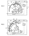
- the switch device 10 illustrated in FIG. 1 is an intensity threshold device comprising in a housing 11 provided with an input terminal E and an output terminal S between which there is an electrical circuit 12 comprising at least two separable contacts; these contacts are shown diagrammatically in FIG. 1 by a fixed contact CF and a movable contact CM.
- the movable contact CM is connected to the terminal S and the fixed contact CF is connected to the input terminal E via a trip device 13.
- the trigger device 13 comprises a magnetic member with a movable armature, for example in the event of overcurrent, to allow, on the one hand, the opening of the contacts by means of a mechanism 14 and, on the other hand, the displacement of the screen using a propellant shown schematically in 15.
- the switch device 10 comprises a rotary screen 20 which has an annular sector 21 in the form of a cylindrical cap and two lateral cheeks 22, 23 for connection with pins 24, 25 allowing pivoting about an axis X-X.
- the screen 20 is molded in one piece from insulating material.
- Annular ribs 26 are provided on the outer face of the cheeks 22, 23, the function of which will be explained below.
- the cheeks of the annular sector in the present example cover an area greater than a quadrant.
- the housing comprises a fixed cylindrical wall 30 delimiting on each side a volume V l -V 3 .
- a cylindrical lamellar space V 3 is generated by the displacement of the screen and is inserted between the volumes V 1 and V 2 .
- the lamellar space V 3 of circumferential length L 1 ′ for example from 5 to 15 mm and of small thickness h, for example from 0.1 to 0.7 mm, is formed between the radially inner face 31 of the wall 30 and the radially outer face 27 of the annular sector 21 of the screen.
- the fixed wall 30 covers a space of approximately one quadrant downstream of the area of the contacts CF, CM with respect to the direction of movement of the screen when the contacts are opened, this direction being represented by the arrow F.
- the lamellar space V 3 defines a path capable of ensuring the rolling, elongation and cooling of the arc and it communicates permanently with a chamber 32 provided in volume V 1 to allow the expulsion of gases with expansion from the space V 3 towards the chamber 32 and from the latter towards the atmosphere.
- a lamellar space V 4 remains downstream of the contact zone during the entire movement of the screen over a length L 2 sufficient to avoid backflow of the arc.
- the fixed cylindrical wall 30 is preferably constituted (FIG. 3) by a partition 33 separating the interior of the housing 11 into a volume V 1 , comprising the chamber 32 and into a volume V 2 comprising a chamber 34; the partition 33 has an opening 35 which allows, on the one hand, the lifting of the movable contact CM towards the chamber 34, on the other hand, the expulsion of the gases of volume V 3 towards this same chamber in addition to their expulsion towards room 32.
- the housing 11 has, opposite the side cheeks 22, 23 of the screen, fixed cheeks 36, 37 extending over a circumferential distance approximately equal to L, + L 2 and provided with annular ribs and grooves 38 and complementary to the ribs and grooves 26 of the rotary screen; the annular elements 38 determine lateral lamellar spaces V5, V 6 respectively associated with the cheeks 22, 23 and of greater length than the radius of the annular sector.
- the switch device shown in FIG. 5 comprises a double-break member 40, more precisely with fixed contacts CF a , CF b and movable contacts CM a , CM b, having the particularity of being provided with two rotary screens 20a, 20b in accordance with the invention; these screens have a notch 28 for the passage of the contacts and they have their pivot axes combined in YY; they cooperate for example by means of a push or pull rod 41 with a single frame of the magnetic trip device 42. This results in great simplicity and a reduced size for the device.
- an element or a drive face 50 for cooperating with a drive means 41 associated with the magnetic trip device (FIG. 1 the latter therefore directly constituting the means of propulsion of the screen; a return device 16 is preferably associated with the screen to return it to its initial position, the drive face 50 is for example advantageously situated on the side opposite the annular sector 27 with respect to the pivot axis XX and radial distance of this axis relatively small compared to the radial distance of the annular sector.
- An energy storage system can be associated with the screen to constitute the means of propulsion of the screen in interdependence with the magnetic trigger 13.
- a drive face is provided on the rotary screen 20 to cooperate with an actuating face of the mechanism 14 for opening the contacts, this mechanism comprising an elastic triggering system.
Landscapes
- Arc-Extinguishing Devices That Are Switches (AREA)
Abstract
Description
- La présente invention concerne un dispositif interrupteur à seuil d'intensité comprenant dans un boîtier une borne d'entrée, une borne de sortie et entre celles-ci un circuit électrique comportant au moins deux contacts séparables, ainsi qu'un écran rotatif présentant une paroi annulaire interposable entre les contacts et déplaçable autour d'un axe avec une course circonférentielle prédéterminée d'une première position à une deuxième position, le déplacement de la paroi annulaire s'effectuant en regard d'une paroi fixe de forme cylindrique et concentrique à la paroi annulaire, la paroi fixe comportant une ouverture pour le passage de l'un au moins des contacts.
- Dans le brevet US-2 714 144, il est décrit un tel dispositif interrupteur utilisant un écran rotatif cylindrique logé entre un noyau intérieur cylindrique fixe et une enveloppe extérieure cylindrique fixe. L'augmentation de pression causée par un arc de coupure risque cependant d'entraîner une explosion du dispositif ; de plus, lors d'un fonctionnement normal du dispositif, les gaz sont évacués à l'atmosphère par un simple évent et provoquent une pollution.
- Il est connu d'après les brevets US-1 833 173 et FR-1 217 162 d'utiliser dans un dispositif interrupteur, pour couper un arc électrique engendré par l'ouverture des contacts, un écran en forme de secteur cylindrique interposable entre les contacts.
- Il convient de rappeler que la coupure d'un arc électrique s'effectue moyennant l'interposition dans le circuit d'une tension d'arc suffisante. Cette tension d'arc correspond à une résistance du plasma de l'arc essentiellement dépendante de sa conductivité J, de sa longueur L et de sa section S suivant la relation Rare = i . i ; d'autre part, la conductivité de l'arc est diminuée lorsqu'on parvient à abaisser sa température. On conçoit de plus que le temps d'apparition de la tension d'arc et son accroissement dV/dt, facteurs prépondérants pour assurer une bonne coupure, seront dépendants de la vitesse de l'écran comme il est dit dans la demande de brevet FR-8 301 749 du 4 Février 1983 de la demanderesse et publié sou le numéro FR-A-2 540 665.
- Les dispositifs interrupteurs à écran rotatif de l'art antérieur ne tirent pas suffisamment parti du caractère rotatif de l'écran et se bornent généralement à confiner l'arc en fin de course dans une fente ou pénètre la tranche antérieure de l'écran. D'autre part, la demande de brevet FR-8 301 749 précitée décrit un dispositif interrupteur faisant appel à un moyen de cisaillement d'arc constitué par un écran rotatif propulsable à vitesse d'au moins 5 m/s entre les contacts et parvenant en fin de course dans une fente de butée étanche. Il en résulte toutefois une forte surpression des gaz ionisés qui nécessite dans certains cas des dispositions appropriées.
- La présente invention a notamment pour but de réaliser un dispositif interrupteur à écran rotatif autorisant de manière simple et peu coûteuse une coupure fiable de l'arc et évitant les risques de pollution et d'explosion.
- Elle a de plus pour but d'agencer le système de coupure de l'arc pour permettre de le loger dans un dispositif interrupteur offrant un faible volume et plus particulièrement une faible épaisseur.
- Selon l'invention, dans un dispositif du type rappelé en préambule de la revendication 1, la paroi fixe cylindrique délimite dans le boîtier deux volumes situés chacun d'un côté de la paroi, tandis qu'un espace lamellaire cylindrique de longueur notable et de faible hauteur est délimité entre la face radialement intérieure de la paroi et la face radialement extérieure du secteur annulaire, pour définir dans ledit espace un cheminement lamellaire susceptible d'assurer le laminage et le refroidissement de l'arc, l'espace lamellaire communiquant en permanence avec l'un au moins des deux volumes pour permettre l'expulsion des gaz avec détente dudit espace vers ledit volume.
- Par laminage, on veut dire présentement que l'on impose une limite supérieure à la section de l'arc.
- Le refroidissement du plasma de l'arc s'effectue donc le long de la paroi fixe concave, la grande longueur de celleci pouvant néanmoins être logée dans un espace relativement réduit du dispositif interrupteur grâce à la forme arrondie de ladite paroi. Cette forme arrondie, en combinaison avec l'axe de pivotement servant d'axe de référence, permet de légères variations du jeu radial entre la paroi fixe et le secteur annulaire sans causer de frottements ou de coincements de l'écran. La paroi fixe peut par exemple s'étendre sur au moins environ un quadrant en aval de la zone des contacts dans le sens de la course de l'écran, afin de provoquer un refroidissement important de l'arc.
- Dans un mode de réalisation préférentiel, le secteur annulaire de l'écran forme une coiffe reliée à l'axe de pivotement par au moins une joue de liaison en forme de secteur circulaire située en regard d'une joue fixe solidaire du boîtier et séparée de celle-ci par un espace lamellaire pour déterminer un cheminement complémentaire latéral et lamellaire de communication entre l'espace lamellaire et le ou les volumes de détente.
- L'intérieur de la coquille ainsi constituée par l'écran détermine une partie du volume de détente.
- La joue de liaison de l'écran et la joue fixe du boîtier peuvent avantageusement présenter des chicanes en forme de nervures et d'encoches annulaires coopérantes d'augmentation du cheminement latéral lamellaire.
- D'autres particularités ainsi que les avantages de l'invention apparaîtront de manière plus détaillée à la lumière de la description ci-après:
- La figure 1 est une vue partielle en coupe longitudinale d'un dispositif interrupteur équipé de l'écran conforme à l'invention, et montre dans sa position de fermeture des contacts ;
- La figure 2 représente l'écran dans sa position d'ouverture des contacts ;
- La figure 3 représente un autre mode de réalisation du dispositif ;
- La figure 4 est la coupe du dispositif de la figure 3 selon le plan IV-IV passant par l'axe de pivotement ;
- La figure 5 montre en perspective un dispositif à double coupure conforme à l'invention.
- Le dispositif interrupteur 10 illustré par la figure 1 est un dispositif à seuil d'intensité comprenant dans un boîtier 11 doté d'une borne d'entrée E et d'une borne de sortie S entre lesquelles se trouve un circuit électrique 12 comportant au moins deux contacts séparables ; ces contacts sont schématisés sur la figure 1 par un contact fixe CF et un contact mobile CM. Le contact mobile CM est relié à la borne S et le contact fixe CF est relié à la borne d'entrée E par l'intermédiaire d'un dispositif déclencheur 13.
- Le dispositif déclencheur 13 comprend un organe magnétique à armature déplaçable par exemple en cas de sur intensité pour permettre, d'une part, l'ouverture des contacts au moyen d'un mécanisme 14 et, d'autre part, le déplacement de l'écran à l'aide d'un moyen propulseur schématisé en 15.
- Le dispositif interrupteur 10 comprend un écran rotatif 20 qui présente un secteur annulaire 21 en forme de coiffe cylindrique et deux joues latérales 22, 23 de liaison avec des tourillons 24, 25 autorisant un pivotement autour d'un axe X-X. L'écran 20 est moulé d'une pièce en matière isolante. Il est prévu sur la face extérieure des joues 22, 23 des nervures annulaires 26 dont la fonction sera expliquée plus loin. Les joues du secteur annulaire couvrent dans le présent exemple une aire supérieure à un quadrant.
- Le boîtier comprend une paroi cylindrique fixe 30 délimitant de chaque côté un volume Vl-V3. Selon l'invention, un espace lamellaire cylindrique V3 est généré par le déplacement de l'écran et s'insère entre les volumes V1 et V2. L'espace lamellaire V3 de longueur circonférentielle L1' par exemple de 5 à 15 mm et de faible épaisseur h, par exemple de 0,1 à 0,7 mm, est ménagé entre la face radialement intérieure 31 de la paroi 30 et la face radialement extérieure 27 du secteur annulaire 21 de l'écran. La paroi fixe 30 couvre un espace d'environ un quadrant en aval de la zone des contacts CF, CM par rapport à la direction de déplacement de l'écran lors d'une ouverture des contacts, cette direction étant représentée par la flèche F.
- L'espace lamellaire V3 définit un cheminement susceptible d'assurer le laminage, l'allongement et le refroidissement de l'arc et il communique en permanence avec une chambre 32 prévue dans le volume V1 pour permettre l'expulsion des gaz avec détente de l'espace V3 vers la chambre 32 et de celle-ci vers l'atmosphère.
- Un espace lamellaire V4 subsiste en aval de la zone des contacts pendant tout le mouvement de l'écran sur une longueur L2 suffisante pour éviter un reflux de l'arc.
- La paroi cylindrique fixe 30 est constituée de préférence (figure 3) par une cloison 33 séparant l'intérieur du boîtier 11 en un volume V1, comprenant la chambre 32 et en un volume V2 comprenant une chambre 34 ; la cloison 33 comporte une ouverture 35 qui permet, d'une part, la levée du contact mobile CM vers la chambre 34, d'autre part, l'expulsion des gaz du volume V3 vers cette même chambre en addition à leur expulsion vers la chambre 32.
- Le boîtier 11 présente en regard des joues latérales 22, 23 de l'écran des joues fixes 36, 37 s'étendant sur une distance circonférentielle environ égale à L, + L2 et dotées de nervures et de rainures 38 annulaires et complémentaires des nervures et rainures 26 de l'écran rotatif ; les éléments de forme annulaire 38 déterminent des espaces lamellaires latéraux V5, V6 respectivement associés aux joues 22, 23 et de longueur plus importante que le rayon du secteur annulaire.
- Ces espaces, par exemple de hauteur comprise entre 0,1 et 0,7 mm, assistent l'espace V3 pour procurer un laminage plus intense et un meilleur refroidissement de l'arc ; les gaz ionisés de l'arc vont en effet trouver dans ces espaces un cheminement lamellaire vers la chambre 32.
- On constate que la nature rotative de l'écran entraîne en combinaison avec les espaces lamellaires V3 à V6 précédemment définis un encombrement réduit en longueur du dispositif interrupteur, ainsi qu'un laminage et un refroidissement importants puisque l'on impose un trajet d'arc à la fois le long du secteur annulaire et des joues latérales de l'écran.
- Le dispositif interrupteur représenté sur la figure 5 comprend un organe à double coupure 40, plus précisément à contacts fixes CFa, CFb et contacts mobiles CMa, CMb présentant la particularité d'être doté de deux écrans rotatifs 20a, 20b conformément à l'invention ; ces écrans possèdent une échancrure 28 pour le passage des contacts et ils ont leurs axes de pivotement confondus en Y-Y ; ils coopèrent par exemple au moyen d'une tige de poussée ou de traction 41 avec une armature unique du déclencheur magnétique 42. Il en résulte une, grande simplicité et un encombrement réduit pour le dispositif.
- Il est avantageusement prévu sur l'écran 20 un élément ou une face d'entraînement 50 pour coopérer avec un moyen d'entraînement 41 associé au déclencheur magnétique (figure 1 celui-ci constituant dès lors directement le moyen de propulsion de l'écran ; on associe de préférence à l'écran un dispositif de rappel 16 pour le ramener à sa position initiale. La face d'entraînement 50 est par exemple située avantageusement du côté opposé au secteur annulaire 27 par rapport à l'axe de pivotement X-X et à distance radiale de cet axe relativement faible par rapport à la distance radiale du secteur annulaire.
- Un système accumulateur d'énergie peut être associé à l'écran pour constituer en interdépendance avec le déclencheur magnétique 13 le moyen de propulsion de l'écran.
- Dans un mode de réalisation très simple, une face d'entraînement est prévue sur l'écran rotatif 20 pour coopérer avec une face d'actionnement du mécanisme 14 d'ouverture des contacts, ce mécanisme comprenant un système de déclenchement élastique.
- Il va de soi que l'on peut apporter des modifications au dispositif interrupteûr décrit sans pour autant sortir du cadre de l'invention.
Claims (14)
caractérisé en ce que:
Applications Claiming Priority (2)
| Application Number | Priority Date | Filing Date | Title |
|---|---|---|---|
| FR8406878A FR2563939B1 (fr) | 1984-05-03 | 1984-05-03 | Dispositif interrupteur a ecran de coupure d'arc |
| FR8406878 | 1984-05-03 |
Publications (2)
| Publication Number | Publication Date |
|---|---|
| EP0179834A1 EP0179834A1 (fr) | 1986-05-07 |
| EP0179834B1 true EP0179834B1 (fr) | 1988-05-18 |
Family
ID=9303661
Family Applications (1)
| Application Number | Title | Priority Date | Filing Date |
|---|---|---|---|
| EP85902063A Expired EP0179834B1 (fr) | 1984-05-03 | 1985-05-03 | Dispositif interrupteur a ecran de coupure d'arc |
Country Status (8)
| Country | Link |
|---|---|
| US (1) | US4647741A (fr) |
| EP (1) | EP0179834B1 (fr) |
| JP (1) | JPS62500333A (fr) |
| DE (1) | DE3562839D1 (fr) |
| ES (1) | ES8608224A1 (fr) |
| FR (1) | FR2563939B1 (fr) |
| SG (1) | SG60088G (fr) |
| WO (1) | WO1985005218A1 (fr) |
Cited By (1)
| Publication number | Priority date | Publication date | Assignee | Title |
|---|---|---|---|---|
| DE10001632A1 (de) * | 2000-01-17 | 2001-08-02 | Harting Automotive Gmbh & Co | Leitungsunterbrecher |
Families Citing this family (17)
| Publication number | Priority date | Publication date | Assignee | Title |
|---|---|---|---|---|
| DE3680902D1 (de) * | 1986-01-10 | 1991-09-19 | Matsushita Electric Works Ltd | Ausschalter. |
| FR2596196B1 (fr) * | 1986-03-21 | 1988-08-26 | Telemecanique Electrique | Appareil interrupteur de protection muni d'un ecran de coupure d'arc |
| FR2596916B1 (fr) * | 1986-04-04 | 1988-06-10 | Telemecanique Electrique | Disjoncteur bipolaire a ouverture automatique ou manuelle avec electro-aimant bistable et noyau percuteur magnetisable |
| DE3770516D1 (de) * | 1986-04-04 | 1991-07-11 | Telemecanique Electrique | Elektrischer schalter fuer schutzgeraet, wie schutzschalter. |
| JPS6346186A (ja) * | 1986-08-13 | 1988-02-27 | 美津濃株式会社 | ロ−イングマシ−ン |
| DE3823790A1 (de) * | 1988-07-14 | 1990-01-18 | Asea Brown Boveri | Elektrisches installationsgeraet mit kontakttrennwand |
| DE4234065C1 (de) * | 1992-10-09 | 1993-12-02 | Eti Elektroelement Dd | Schaltgerät |
| JP4887523B2 (ja) * | 2000-12-28 | 2012-02-29 | リンテック株式会社 | 多面体検査用フィーダー及び多面体検査装置 |
| US20050191758A1 (en) * | 2002-08-26 | 2005-09-01 | John Pether | Soil test box |
| KR101771465B1 (ko) * | 2011-07-25 | 2017-09-06 | 엘에스산전 주식회사 | 가스절연 개폐장치 |
| CN108987139B (zh) * | 2017-06-01 | 2024-02-02 | 泰科电子(深圳)有限公司 | 电触头系统 |
| CN108987140B (zh) * | 2017-06-01 | 2024-04-02 | 泰科电子(深圳)有限公司 | 电触头系统 |
| CN108987141B (zh) * | 2017-06-05 | 2023-04-07 | 泰科电子(深圳)有限公司 | 电触头系统 |
| US10186804B2 (en) | 2017-06-20 | 2019-01-22 | Amphenol Corporation | Cable connector with backshell locking |
| FR3138559B1 (fr) * | 2022-07-26 | 2024-06-28 | Socomec Sa | Module de coupure électrique avec barrière diélectrique |
| FR3142282B1 (fr) | 2022-11-21 | 2025-02-14 | Safran Electrical & Power | Contacteur de puissance a ecran de clarification d’arc electrique et aeronef comportant un tel contacteur de puissance |
| EP4376038A1 (fr) * | 2022-11-28 | 2024-05-29 | ABB Schweiz AG | Commutateur électrique |
Family Cites Families (10)
| Publication number | Priority date | Publication date | Assignee | Title |
|---|---|---|---|---|
| US663612A (en) * | 1899-05-29 | 1900-12-11 | Gen Electric | Circuit-changer. |
| US1833173A (en) * | 1928-07-10 | 1931-11-24 | Metropolitan Device Corp | Circuit breaking apparatus |
| DE735601C (de) * | 1940-11-21 | 1943-05-19 | Aeg | Elektrischer Gasschalter |
| US2493419A (en) * | 1947-08-12 | 1950-01-03 | Joseph M Puffer | Switch for floor lamps |
| US2714144A (en) * | 1953-04-22 | 1955-07-26 | Mcgraw Electric Co | Circuit interrupter |
| DE1015897B (de) * | 1954-12-07 | 1957-09-19 | Busch Jaeger Duerener Metall | Nockenregelschalter |
| US2928910A (en) * | 1958-09-03 | 1960-03-15 | John P E Watterberg | Rotary switch |
| FR1217162A (fr) * | 1958-12-02 | 1960-05-02 | Parisienne De Const Electro Me | Interrupteur électrique à écran |
| FR1282733A (fr) * | 1960-12-17 | 1962-01-27 | Appareil interrupteur pour la coupure en charge du courant électrique | |
| US4426562A (en) * | 1981-10-06 | 1984-01-17 | Westinghouse Electric Corp. | Rotary switch for switching very large DC currents |
-
1984
- 1984-05-03 FR FR8406878A patent/FR2563939B1/fr not_active Expired
-
1985
- 1985-04-30 ES ES542764A patent/ES8608224A1/es not_active Expired
- 1985-05-03 WO PCT/FR1985/000105 patent/WO1985005218A1/fr not_active Ceased
- 1985-05-03 DE DE8585902063T patent/DE3562839D1/de not_active Expired
- 1985-05-03 US US06/835,866 patent/US4647741A/en not_active Expired - Fee Related
- 1985-05-03 EP EP85902063A patent/EP0179834B1/fr not_active Expired
- 1985-05-03 JP JP60502078A patent/JPS62500333A/ja active Pending
-
1988
- 1988-08-15 SG SG60088A patent/SG60088G/en unknown
Cited By (1)
| Publication number | Priority date | Publication date | Assignee | Title |
|---|---|---|---|---|
| DE10001632A1 (de) * | 2000-01-17 | 2001-08-02 | Harting Automotive Gmbh & Co | Leitungsunterbrecher |
Also Published As
| Publication number | Publication date |
|---|---|
| EP0179834A1 (fr) | 1986-05-07 |
| US4647741A (en) | 1987-03-03 |
| WO1985005218A1 (fr) | 1985-11-21 |
| DE3562839D1 (en) | 1988-06-23 |
| SG60088G (en) | 1989-04-21 |
| FR2563939B1 (fr) | 1988-03-18 |
| ES542764A0 (es) | 1986-06-01 |
| FR2563939A1 (fr) | 1985-11-08 |
| JPS62500333A (ja) | 1987-02-05 |
| ES8608224A1 (es) | 1986-06-01 |
Similar Documents
| Publication | Publication Date | Title |
|---|---|---|
| WO1985005218A1 (fr) | Dispositif interrupteur a ecran de coupure d'arc | |
| EP0346249B1 (fr) | Disjoncteur limiteur basse tension à chambre de coupure étanche | |
| EP1115132B1 (fr) | Pôle pour disjoncteur électrique, muni d'une chambre d'extinction d'arc à écrans diélectriques | |
| FR2720188A1 (fr) | Disjoncteur à autocompression réduite. | |
| EP0186546B1 (fr) | Interrupteur électrique à écran | |
| EP0807946B1 (fr) | Disjoncteur à haute tension à auto-soufflage | |
| EP0817224B1 (fr) | Dispositif de coupure pour un disjoncteur électrique à forts calibres | |
| FR2722912A1 (fr) | Interrupteurs electriques moyenne tension | |
| EP1235243B1 (fr) | Disjoncteur incluant un canal de vidange de la chambre de compression par piston | |
| EP0485306A1 (fr) | Interrupteur rotatif multipolaire | |
| EP0895262A1 (fr) | Interrupteur à gaz à volume d'expansion thermique compressible | |
| FR2767221A1 (fr) | Disjoncteur a auto-soufflage et a compression reduite | |
| EP0884745B1 (fr) | Disjoncteur à résistance de fermeture | |
| EP0021951A1 (fr) | Interrupteur à autosoufflage par aspiration | |
| CA2101214C (fr) | Disjoncteur a deux chambres de coupure concentriques | |
| EP2402970B1 (fr) | Chambre de coupure pour disjoncteur a moyenne ou haute tension a energie de manoeuvre et dimensions reduites | |
| FR2575594A1 (fr) | Disjoncteur a gaz dielectrique sous pression a auto-soufflage | |
| FR2634942A1 (fr) | Dispositif d'extinction d'arc electrique pour un commutateur basse tension limitant le courant de court-circuit | |
| FR2662540A1 (fr) | Disjoncteur a moyenne tension. | |
| EP0101371B1 (fr) | Interrupteur électrique à arc tournant | |
| EP0986081A1 (fr) | Interrupteur avec un système d'insertion d'une résistance à longue durée d'insertion | |
| CH688702A5 (fr) | Disjoncteur à haute tension ayant une chambre de coupure à volume de soufflage variable. | |
| FR2563372A1 (fr) | Disjoncteur haute tension a soufflage d'arc | |
| FR2733352A1 (fr) | Pole pour appareil limiteur de courant | |
| FR2761520A1 (fr) | Disjoncteur a moyenne tension a faible energie de manoeuvre |
Legal Events
| Date | Code | Title | Description |
|---|---|---|---|
| PUAI | Public reference made under article 153(3) epc to a published international application that has entered the european phase |
Free format text: ORIGINAL CODE: 0009012 |
|
| 17P | Request for examination filed |
Effective date: 19851230 |
|
| AK | Designated contracting states |
Kind code of ref document: A1 Designated state(s): BE CH DE GB IT LI NL SE |
|
| 17Q | First examination report despatched |
Effective date: 19870616 |
|
| GRAA | (expected) grant |
Free format text: ORIGINAL CODE: 0009210 |
|
| AK | Designated contracting states |
Kind code of ref document: B1 Designated state(s): BE CH DE GB IT LI NL SE |
|
| ITF | It: translation for a ep patent filed | ||
| GBT | Gb: translation of ep patent filed (gb section 77(6)(a)/1977) | ||
| REF | Corresponds to: |
Ref document number: 3562839 Country of ref document: DE Date of ref document: 19880623 |
|
| PLBE | No opposition filed within time limit |
Free format text: ORIGINAL CODE: 0009261 |
|
| STAA | Information on the status of an ep patent application or granted ep patent |
Free format text: STATUS: NO OPPOSITION FILED WITHIN TIME LIMIT |
|
| 26N | No opposition filed | ||
| ITTA | It: last paid annual fee | ||
| EAL | Se: european patent in force in sweden |
Ref document number: 85902063.8 |
|
| PGFP | Annual fee paid to national office [announced via postgrant information from national office to epo] |
Ref country code: NL Payment date: 19960422 Year of fee payment: 12 |
|
| PGFP | Annual fee paid to national office [announced via postgrant information from national office to epo] |
Ref country code: GB Payment date: 19960426 Year of fee payment: 12 |
|
| PGFP | Annual fee paid to national office [announced via postgrant information from national office to epo] |
Ref country code: DE Payment date: 19960524 Year of fee payment: 12 |
|
| PGFP | Annual fee paid to national office [announced via postgrant information from national office to epo] |
Ref country code: SE Payment date: 19960528 Year of fee payment: 12 Ref country code: CH Payment date: 19960528 Year of fee payment: 12 |
|
| PGFP | Annual fee paid to national office [announced via postgrant information from national office to epo] |
Ref country code: BE Payment date: 19960612 Year of fee payment: 12 |
|
| PG25 | Lapsed in a contracting state [announced via postgrant information from national office to epo] |
Ref country code: GB Effective date: 19970503 |
|
| PG25 | Lapsed in a contracting state [announced via postgrant information from national office to epo] |
Ref country code: SE Effective date: 19970504 |
|
| PG25 | Lapsed in a contracting state [announced via postgrant information from national office to epo] |
Ref country code: LI Free format text: LAPSE BECAUSE OF NON-PAYMENT OF DUE FEES Effective date: 19970531 Ref country code: CH Free format text: LAPSE BECAUSE OF NON-PAYMENT OF DUE FEES Effective date: 19970531 Ref country code: BE Effective date: 19970531 |
|
| BERE | Be: lapsed |
Owner name: LA TELEMECANIQUE ELECTRIQUE Effective date: 19970531 |
|
| PG25 | Lapsed in a contracting state [announced via postgrant information from national office to epo] |
Ref country code: NL Effective date: 19971201 |
|
| GBPC | Gb: european patent ceased through non-payment of renewal fee |
Effective date: 19970503 |
|
| REG | Reference to a national code |
Ref country code: CH Ref legal event code: PL |
|
| EUG | Se: european patent has lapsed |
Ref document number: 85902063.8 |
|
| NLV4 | Nl: lapsed or anulled due to non-payment of the annual fee |
Effective date: 19971201 |
|
| PG25 | Lapsed in a contracting state [announced via postgrant information from national office to epo] |
Ref country code: DE Free format text: LAPSE BECAUSE OF NON-PAYMENT OF DUE FEES Effective date: 19980203 |