EP0179722B1 - Joint d'étanchéité pneumatique de sécurité en élastomère à cloison intérieure - Google Patents
Joint d'étanchéité pneumatique de sécurité en élastomère à cloison intérieure Download PDFInfo
- Publication number
- EP0179722B1 EP0179722B1 EP85420155A EP85420155A EP0179722B1 EP 0179722 B1 EP0179722 B1 EP 0179722B1 EP 85420155 A EP85420155 A EP 85420155A EP 85420155 A EP85420155 A EP 85420155A EP 0179722 B1 EP0179722 B1 EP 0179722B1
- Authority
- EP
- European Patent Office
- Prior art keywords
- internal
- partition
- sealing
- width
- side walls
- Prior art date
- Legal status (The legal status is an assumption and is not a legal conclusion. Google has not performed a legal analysis and makes no representation as to the accuracy of the status listed.)
- Expired
Links
- 238000005192 partition Methods 0.000 title claims description 44
- 239000013536 elastomeric material Substances 0.000 title 1
- 238000012856 packing Methods 0.000 title 1
- 238000007789 sealing Methods 0.000 claims description 23
- 229920001971 elastomer Polymers 0.000 claims description 4
- 239000000806 elastomer Substances 0.000 claims description 4
- 239000012530 fluid Substances 0.000 description 5
- 238000005553 drilling Methods 0.000 description 4
- 230000000694 effects Effects 0.000 description 3
- 238000009434 installation Methods 0.000 description 2
- 239000012528 membrane Substances 0.000 description 2
- 229920003048 styrene butadiene rubber Polymers 0.000 description 2
- 238000013459 approach Methods 0.000 description 1
- 230000009849 deactivation Effects 0.000 description 1
- 230000003247 decreasing effect Effects 0.000 description 1
- 238000001514 detection method Methods 0.000 description 1
- 230000006866 deterioration Effects 0.000 description 1
- 238000001125 extrusion Methods 0.000 description 1
- 239000000446 fuel Substances 0.000 description 1
- 238000012423 maintenance Methods 0.000 description 1
- 239000000463 material Substances 0.000 description 1
- 239000002184 metal Substances 0.000 description 1
- 229920000642 polymer Polymers 0.000 description 1
- 238000012958 reprocessing Methods 0.000 description 1
- 238000000926 separation method Methods 0.000 description 1
- 239000004753 textile Substances 0.000 description 1
Images

Classifications
-
- F—MECHANICAL ENGINEERING; LIGHTING; HEATING; WEAPONS; BLASTING
- F16—ENGINEERING ELEMENTS AND UNITS; GENERAL MEASURES FOR PRODUCING AND MAINTAINING EFFECTIVE FUNCTIONING OF MACHINES OR INSTALLATIONS; THERMAL INSULATION IN GENERAL
- F16J—PISTONS; CYLINDERS; SEALINGS
- F16J15/00—Sealings
- F16J15/46—Sealings with packing ring expanded or pressed into place by fluid pressure, e.g. inflatable packings
-
- Y—GENERAL TAGGING OF NEW TECHNOLOGICAL DEVELOPMENTS; GENERAL TAGGING OF CROSS-SECTIONAL TECHNOLOGIES SPANNING OVER SEVERAL SECTIONS OF THE IPC; TECHNICAL SUBJECTS COVERED BY FORMER USPC CROSS-REFERENCE ART COLLECTIONS [XRACs] AND DIGESTS
- Y10—TECHNICAL SUBJECTS COVERED BY FORMER USPC
- Y10S—TECHNICAL SUBJECTS COVERED BY FORMER USPC CROSS-REFERENCE ART COLLECTIONS [XRACs] AND DIGESTS
- Y10S277/00—Seal for a joint or juncture
- Y10S277/914—Backup seal for failure of primary seal
-
- Y—GENERAL TAGGING OF NEW TECHNOLOGICAL DEVELOPMENTS; GENERAL TAGGING OF CROSS-SECTIONAL TECHNOLOGIES SPANNING OVER SEVERAL SECTIONS OF THE IPC; TECHNICAL SUBJECTS COVERED BY FORMER USPC CROSS-REFERENCE ART COLLECTIONS [XRACs] AND DIGESTS
- Y10—TECHNICAL SUBJECTS COVERED BY FORMER USPC
- Y10S—TECHNICAL SUBJECTS COVERED BY FORMER USPC CROSS-REFERENCE ART COLLECTIONS [XRACs] AND DIGESTS
- Y10S277/00—Seal for a joint or juncture
- Y10S277/926—Seal including fluid pressure equalizing or balancing feature
Definitions
- the present invention relates to a pneumatic gasket made of elastomer with improved safety, thanks to an internal partition.
- retractable pneumatic seals inflatable under the pressure of a fluid, for sealing between two chambers, chambers, tanks, or between them and the outside. This is the case, in particular, in wind tunnels, irradiation chambers, amphibious vehicles, air and space vehicles, for the doors or cofferdams of the deactivation pools of nuclear power plants, the irradiated fuel reprocessing workshops, the so-called " white ”of the electronics and space industries, the sterile rooms of hospitals.
- the safety device currently used, consists in placing inside the joint cavity, an air chamber or an impermeable membrane containing the air or the working fluid and according to all the stresses of the profile.
- textile inserts commonly used in tires, reinforce the walls. Tears or cuts on the outside of the joint do not necessarily lead to perforation of the walls or the internal membrane. It is the system used on all automotive, cycle and motorcycle tires.
- the internal chamber of the joint is also perforated since it lines the interior of the profile perfectly; the seal is therefore destroyed, which, in most of the applications mentioned above, is unacceptable, since it may result in harmful consequences for the safety of people and property.
- US Pat. No. 3,359,687 furthermore describes an expandable inflatable seal for an aeronautical pressurization system, comprising two watertight compartments with individually inflatable corrugated walls separated by a wall.
- the height of the joint in service is obtained by inflating a single compartment with higher pressure, the other less inflated compartment remaining retracted.
- the pressure in the other compartment causes it to expand, which makes it possible to maintain the height of the joint.
- the partition separating the two individually expandable compartments plays a role of inert leaktight separation.
- the invention proposes to solve the problem of the safety of an inflatable elastomeric seal in a manner different from that described by patent US-A-3,359,687, in which the partition separating the seal into two chambers intervenes itself to maintain the seal in case of piercing.
- the sealed internal partition of the invention deforms under the effect of the pressure of the other chamber and comes to bear on the external sealing wall or the wall foot of the drilled chamber so that the seal that the seal provides is preserved.
- the two chambers of the seal of the invention are inflated to equal pressures and have comparable wall thicknesses, so that the ratio of their respective volumes remains substantially constant when passing from the retracted state or from rest in the swollen state.
- the two chambers have substantially equal volumes with respective volumes in a ratio of between 0.95 and 1.05.
- the developed width of the sealed internal partition of the joint after deformation under the effect of the differential pressure resulting from the drilling of a chamber, must be sufficient for this partition to come into contact and to bear on the wall of the pierced chamber.
- the ratio of the developed width of the interior partition to the interior width should also preferably be greater when the joint will tend less to deform to round off upon inflation, that is to say when its ratio " I / H "will decrease as it approaches 1.
- the thickness of the interior partition of the invention must also preferably be sufficiently small to make its extension and its deformations easy, but not too small with respect to the risks of subsequent piercing.
- the thickness of the side walls, or their smallest thickness when these have variations, is taken as a benchmark, and it is preferable that the thickness of the interior partition at rest is between 0.6 and 1 time this side wall thickness, and optimally that it is between 0.7 times and 0.9 times this thickness, so as to allow good preferential deformation of the sealed interior partition in the event of drilling.
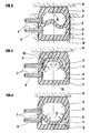
- the joint of the first example (1) has in the inflated state (FIG. 1) a maximum internal width (I) of 28 mm and a maximum internal height (H) of 24 mm. It has a sealed internal partition (2) with a developed width (L) equal to 36 mm, or 1.28 times the internal width (1), which separates the internal volume of the seal into two chambers, upper (3) and lower ( 4), of substantially equal volumes.
- This 3 mm thick corrugated partition (2) is connected, at its two ends, to the internal faces of the side walls (8) (9) of the 3.5 mm thick joint, at the same height of these internal faces.
- Each chamber (3) (4) is provided with at least one valve connection (7) which connects it to a source of pressurized fluid, so that the two chambers are subjected to the same pressure.
- These fittings are placed laterally (as shown) or on the back of the joint in the case of a joint closed on itself, often a circular joint, and they are placed at the end of the joint and fixed to the plates or plugs of elastomer which close them at their ends when they are linear joints.
- the seal (1) When the seal (1) is inflated (FIG. 2) to the same pressure of 1.3 bar for the two chambers, the internal height of the seal increases to become close to its internal width, while this internal width and the developed width of the interior partition (2) remains substantially constant.
- the corrugated interior partition (2) has an unstable equilibrium position between the chambers (3) and (4), it can occupy any position inside the joint (1) without significant constraint.
- the seal is arranged in a groove (12), cut, for example, in the fixed wall of a sealed enclosure (1), the sealing face (5) coming to bear on the flat surface (6) which is, for example, the door or the movable element of the sealed enclosure.
- the groove can be cut in the movable member.
- the chamber (3) loses its pressure and the partition (2) is subjected at a pressure difference compared to the other chamber (4) which remains intact.
- the partition (2) therefore deforms under the effect of the pressure of the chamber (4) and comes into contact with the vault (10) of the chamber (3) which is then at atmospheric pressure, or, at all less, at a pressure lower than that of the chamber (4).
- the seal is therefore preserved. It is possible, if necessary, upon detection of the perforation (11), to increase the pressure of the intact chamber (4).
- Figure 4 shows the opposite situation where the perforation (11) affected the lower chamber (4); the partition (2) then comes to bear on the internal wall of the foot (13) of the chamber (4) which has fallen to atmospheric pressure; the seal on the bearing surface (6) is, in the same way, preserved.
- the good support of the partition (2) is linked both to its ripple or additional initial developed width and to the additional elongation due to the pressure of the non-pierced chamber, and it is facilitated by the thickness of the partition (2) slightly less than that of the side walls (7) (8).
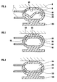
- the joint of the second example (100) is of oval type and has, in the non-inflated state (FIG. 5), a maximum internal width (I) of 107 mm and a maximum internal height (H) of 25 mm, ie a ratio I / H of 4.1, with a wall thickness of 10 mm. It comprises an internal watertight partition (20), of width developed at rest 107 mm, width equal to the internal width (1), and of thickness 7.5 mm.
- This internal partition (20) is connected to the internal faces of the side walls (80) (90) perpendicularly and substantially at mid-height of these side walls, the height of these walls can then be appreciated "rounded connection included" and it separates the internal volume into two chambers (30) and (40) having substantially the same volume.
- the inflated seal (100) ( Figure 6) has decreased in width and increased in height, and its bulkhead (20) is now corrugated.
- the prior undulation of this partition which prepares its support in the event of the piercing of one of the two chambers (30) or (40), is thus obtained by the deformation specific to this form of joint (neighboring I / H of 4) during its inflation.
- the two chambers are inflated at the same pressure and the watertight partition (20) has an unstable equilibrium position between these two chambers.
- Figures 7 and 8 show the same drilling situations as Figures 3 and 4: when the upper chamber (30) is pierced by a perforation (110) ( Figure 7), the interior partition (20) comes into contact with the arch (101) and supports this arch (101), while, when the lower chamber (40) is pierced by a perforation (110), the partition (20) comes to bear on the internal wall of the foot (130).
- This second type of seal is designed to be mounted by its foot (130) in a groove, of the “dovetail” type for example, while other forms of seals according to the invention, provided for operating pressures relatively low, require neither groove nor groove for their installation.
- the height of the joint is 130 mm (instead of 74 mm under pressure in the so-called “retracted” state).
- the height is still 120 mm, which is very largely sufficient to ensure, for example, the tightness of the slide rails of the cofferdams in the reactor pools, where the normal play can be, for example, of the order of 100 mm.
- this type of seal can withstand an internal pressure at least equal to 3 times its operating pressure in one or the other chamber or in both, due to the presence of the central partition limiting the forces on the side walls.
- the use of the internal partition seal, object of the invention notably improves the safety of sealing devices, in particular in the nuclear, aerospace, electronic and medical fields.
Landscapes
- Engineering & Computer Science (AREA)
- General Engineering & Computer Science (AREA)
- Physics & Mathematics (AREA)
- Architecture (AREA)
- Fluid Mechanics (AREA)
- Mechanical Engineering (AREA)
- Sealing Devices (AREA)
- Gasket Seals (AREA)
- Specific Sealing Or Ventilating Devices For Doors And Windows (AREA)
Applications Claiming Priority (2)
| Application Number | Priority Date | Filing Date | Title |
|---|---|---|---|
| FR8413681 | 1984-08-30 | ||
| FR8413681 | 1984-08-30 |
Publications (2)
| Publication Number | Publication Date |
|---|---|
| EP0179722A1 EP0179722A1 (fr) | 1986-04-30 |
| EP0179722B1 true EP0179722B1 (fr) | 1987-12-09 |
Family
ID=9307467
Family Applications (1)
| Application Number | Title | Priority Date | Filing Date |
|---|---|---|---|
| EP85420155A Expired EP0179722B1 (fr) | 1984-08-30 | 1985-08-28 | Joint d'étanchéité pneumatique de sécurité en élastomère à cloison intérieure |
Country Status (4)
| Country | Link |
|---|---|
| US (1) | US4624465A (enExample) |
| EP (1) | EP0179722B1 (enExample) |
| JP (1) | JPS6174975A (enExample) |
| DE (1) | DE3561175D1 (enExample) |
Families Citing this family (24)
| Publication number | Priority date | Publication date | Assignee | Title |
|---|---|---|---|---|
| US5048570A (en) * | 1986-04-21 | 1991-09-17 | Combustion Engineering Inc. | Multisectioned nozzle dam |
| DE3636600A1 (de) * | 1986-10-28 | 1988-05-05 | Hoesch Maschinenfabrik Ag | Heizpresse zum verpressen von technischen laminaten |
| DE3813573C1 (enExample) * | 1988-04-22 | 1989-12-07 | Effem Gmbh, 2810 Verden, De | |
| US4993722A (en) * | 1988-12-07 | 1991-02-19 | Npc, Inc. | Apparatus and method for improved pipe to manhole sealing |
| FR2665499B1 (fr) * | 1990-07-10 | 1994-01-28 | Joint Francais | Dispositif d'etancheite a joint gonflable pour porte ou panneau mobile. |
| GB2247055A (en) * | 1990-07-19 | 1992-02-19 | Yorkshire Water Services Ltd | Seals for use in pipeline systems |
| US5580068A (en) * | 1990-07-27 | 1996-12-03 | Npc, Inc. | Liquid filled seal |
| US5102150A (en) * | 1991-02-19 | 1992-04-07 | The United States Of America As Represented By The Administrator Of The National Aeronautics And Space Administration | Pressure vessel flex joint |
| GB9107864D0 (en) * | 1991-04-12 | 1991-05-29 | Raychem Sa Nv | Environmental sealing |
| US5341726A (en) * | 1993-03-31 | 1994-08-30 | Watson M Burnell | Piston for tank |
| US5941536A (en) * | 1998-02-12 | 1999-08-24 | Envirotech Pumpsystems, Inc. | Elastomer seal for adjustable side liners of pumps |
| US6206248B1 (en) | 1999-04-16 | 2001-03-27 | James L. Popp | Dispensing piston for commodity container |
| DE19940235C1 (de) * | 1999-08-25 | 2000-09-28 | Neugart Gmbh & Co | Getriebe, insbesondere Planetengetriebe, mit Druckausgleich |
| US6481927B2 (en) | 2001-04-11 | 2002-11-19 | Lester Kent Rhodes | Assembly and method for joining a drain pipe and a catch basin |
| US20100132264A1 (en) * | 2008-12-01 | 2010-06-03 | Steven Campbell | Bi-flow inflatable door seals |
| FR2951518B1 (fr) * | 2009-10-15 | 2014-09-05 | Jose Collados | Dispositif d'etancheite et son procede de gonflage. |
| US9383037B2 (en) | 2010-01-28 | 2016-07-05 | Vat Holding Ag | Device for closing an opening in a chamber wall |
| US20110241342A1 (en) * | 2010-04-01 | 2011-10-06 | Skellern Michael J | Pipe Repair Clamp with Self Pressurizing Seal |
| SE539200C2 (en) * | 2015-09-09 | 2017-05-09 | BAE Systems Hägglunds AB | Sealing arrangement for an amphibious vehicle |
| US11592106B2 (en) * | 2018-04-29 | 2023-02-28 | Sean P. Thomas | Hollow annular seal for equipment disposed in a subsea environment |
| WO2019226164A1 (en) * | 2018-05-24 | 2019-11-28 | Halliburton Energy Services, Inc. | Rolling seal for transfer of pressure in a downhole tool |
| GB201908783D0 (en) * | 2019-06-19 | 2019-07-31 | Tokamak Energy Ltd | Metal sealing ring and method of forming a metal-to-metal seal |
| CN110388525B (zh) * | 2019-08-16 | 2024-06-11 | 钱建统 | 一种适用于高压风炮的气动快速接头 |
| CN112902541B (zh) * | 2021-02-02 | 2022-06-17 | 深圳市均佳机电设备有限公司 | 一种用于可变容量冷库的密封保温系统 |
Citations (1)
| Publication number | Priority date | Publication date | Assignee | Title |
|---|---|---|---|---|
| US3359687A (en) * | 1964-08-17 | 1967-12-26 | Haveg Industries Inc | Expansible seal |
Family Cites Families (8)
| Publication number | Priority date | Publication date | Assignee | Title |
|---|---|---|---|---|
| US2700196A (en) * | 1950-12-28 | 1955-01-25 | Panhard & Levassor | Inflatable weather strip for mounting vehicle windows in frames |
| US3178779A (en) * | 1962-06-28 | 1965-04-20 | North American Aviation Inc | Multi-cell inflatable seal |
| US3262707A (en) * | 1963-04-26 | 1966-07-26 | Williams Res Corp | High pressure seal used in conjunction with regenerator |
| US3161229A (en) * | 1963-06-19 | 1964-12-15 | Koppers Co Inc | Seal configuration for folding partition |
| DE1187871B (de) * | 1963-07-02 | 1965-02-25 | Weill & Reineke | Dichtungsprofil aus elastischem Material |
| FR2243619A5 (enExample) * | 1973-09-06 | 1975-04-04 | Joint Francais | |
| JPS53129757A (en) * | 1977-04-19 | 1978-11-13 | Doryokuro Kakunenryo | Sealing of moving member with hollow packing |
| JPS57166U (enExample) * | 1980-06-02 | 1982-01-05 |
-
1985
- 1985-08-26 US US06/769,028 patent/US4624465A/en not_active Expired - Fee Related
- 1985-08-28 EP EP85420155A patent/EP0179722B1/fr not_active Expired
- 1985-08-28 DE DE8585420155T patent/DE3561175D1/de not_active Expired
- 1985-08-29 JP JP60190870A patent/JPS6174975A/ja active Granted
Patent Citations (1)
| Publication number | Priority date | Publication date | Assignee | Title |
|---|---|---|---|---|
| US3359687A (en) * | 1964-08-17 | 1967-12-26 | Haveg Industries Inc | Expansible seal |
Also Published As
| Publication number | Publication date |
|---|---|
| US4624465A (en) | 1986-11-25 |
| EP0179722A1 (fr) | 1986-04-30 |
| DE3561175D1 (en) | 1988-01-21 |
| JPH0469310B2 (enExample) | 1992-11-05 |
| JPS6174975A (ja) | 1986-04-17 |
Similar Documents
| Publication | Publication Date | Title |
|---|---|---|
| EP0179722B1 (fr) | Joint d'étanchéité pneumatique de sécurité en élastomère à cloison intérieure | |
| EP2243678B1 (fr) | Ensemble de joints pour une porte | |
| KR20000069958A (ko) | 신속히 분리 가능한 창유리 | |
| EP1985471A2 (fr) | Pneumatique à bruit de roulement réduit | |
| EP3366932B1 (fr) | Insert à sertir, élément et ensemble de fixation comprenant un tel insert et procédés de fabrication de telles pièces | |
| EP2071216A1 (fr) | Joint d'étanchéité superplastique, de préférence pour système à cellules électrochimiques | |
| US8741407B2 (en) | Tube system | |
| EP1206357A1 (fr) | Ensemble d'une jante et d'un appui de soutien | |
| EP1985470B1 (fr) | Pneumatique comportant une couche alvéolaire | |
| KR200363185Y1 (ko) | 배관용 연결구 | |
| WO2008148944A1 (fr) | Dispositif d'etancheite servant a obturer un puits et une canalisation et un procede de montage | |
| FR2800147A1 (fr) | Joint metallique statique et procede de fabrication | |
| FR2937107A1 (fr) | Joint composite deformable pour portees a fort defaut de planeite. | |
| US20150090007A1 (en) | Method for detecting leaks in aircraft wings | |
| JP2003200720A (ja) | タイヤの突き刺し爆発防止構造 | |
| US10118708B2 (en) | Evacuation slide with beam structure comprising four-point cross section | |
| FR2745622A1 (fr) | Joint et son procede de montage par clipage | |
| FR2488729A1 (fr) | Chambre a vide pour accelerateur de particules chargees | |
| FR2683248A1 (fr) | Armature tubulaire gonflable de securite pour des tentes et des articles analogues. | |
| KR100920059B1 (ko) | 스턴튜브 부시유니트 및 그 설치방법 | |
| JPH0639317Y2 (ja) | フランジ管接合部の耐圧試験装置 | |
| JPH11351400A (ja) | ガスケット用複合シートおよびその複合シートを用いた複合ガスケット | |
| FR2608086A1 (fr) | Procede de separation de deux enceintes etanches accolees et double porte pour la mise en oeuvre de ce procede | |
| CA2782756A1 (fr) | Bourrelet de pneumatique pour vehicule lourd de type genie civil | |
| EP0849512B1 (fr) | Assemblage étanche bord à bord de deux éléments de construction en particulier pour réservoir de gaz sous pression |
Legal Events
| Date | Code | Title | Description |
|---|---|---|---|
| PUAI | Public reference made under article 153(3) epc to a published international application that has entered the european phase |
Free format text: ORIGINAL CODE: 0009012 |
|
| AK | Designated contracting states |
Kind code of ref document: A1 Designated state(s): DE FR GB IT SE |
|
| 17P | Request for examination filed |
Effective date: 19860520 |
|
| 17Q | First examination report despatched |
Effective date: 19870422 |
|
| GRAA | (expected) grant |
Free format text: ORIGINAL CODE: 0009210 |
|
| AK | Designated contracting states |
Kind code of ref document: B1 Designated state(s): DE FR GB IT SE |
|
| ITF | It: translation for a ep patent filed | ||
| REF | Corresponds to: |
Ref document number: 3561175 Country of ref document: DE Date of ref document: 19880121 |
|
| GBT | Gb: translation of ep patent filed (gb section 77(6)(a)/1977) | ||
| REG | Reference to a national code |
Ref country code: FR Ref legal event code: TP |
|
| PLBE | No opposition filed within time limit |
Free format text: ORIGINAL CODE: 0009261 |
|
| STAA | Information on the status of an ep patent application or granted ep patent |
Free format text: STATUS: NO OPPOSITION FILED WITHIN TIME LIMIT |
|
| 26N | No opposition filed | ||
| ITTA | It: last paid annual fee | ||
| EAL | Se: european patent in force in sweden |
Ref document number: 85420155.5 |
|
| REG | Reference to a national code |
Ref country code: FR Ref legal event code: CA |
|
| PGFP | Annual fee paid to national office [announced via postgrant information from national office to epo] |
Ref country code: GB Payment date: 19960613 Year of fee payment: 12 |
|
| PGFP | Annual fee paid to national office [announced via postgrant information from national office to epo] |
Ref country code: FR Payment date: 19960716 Year of fee payment: 12 |
|
| PGFP | Annual fee paid to national office [announced via postgrant information from national office to epo] |
Ref country code: DE Payment date: 19960722 Year of fee payment: 12 |
|
| PGFP | Annual fee paid to national office [announced via postgrant information from national office to epo] |
Ref country code: SE Payment date: 19960723 Year of fee payment: 12 |
|
| REG | Reference to a national code |
Ref country code: GB Ref legal event code: 732E |
|
| PG25 | Lapsed in a contracting state [announced via postgrant information from national office to epo] |
Ref country code: GB Free format text: LAPSE BECAUSE OF NON-PAYMENT OF DUE FEES Effective date: 19970828 |
|
| PG25 | Lapsed in a contracting state [announced via postgrant information from national office to epo] |
Ref country code: SE Free format text: LAPSE BECAUSE OF NON-PAYMENT OF DUE FEES Effective date: 19970829 |
|
| GBPC | Gb: european patent ceased through non-payment of renewal fee |
Effective date: 19970828 |
|
| PG25 | Lapsed in a contracting state [announced via postgrant information from national office to epo] |
Ref country code: FR Free format text: LAPSE BECAUSE OF NON-PAYMENT OF DUE FEES Effective date: 19980430 |
|
| PG25 | Lapsed in a contracting state [announced via postgrant information from national office to epo] |
Ref country code: DE Free format text: LAPSE BECAUSE OF NON-PAYMENT OF DUE FEES Effective date: 19980501 |
|
| EUG | Se: european patent has lapsed |
Ref document number: 85420155.5 |
|
| REG | Reference to a national code |
Ref country code: FR Ref legal event code: ST |