EP0179567A2 - Abbrechungs- und Verdichtungsraupe und Verbindung für ein Raupenfahrzeug - Google Patents
Abbrechungs- und Verdichtungsraupe und Verbindung für ein Raupenfahrzeug Download PDFInfo
- Publication number
- EP0179567A2 EP0179567A2 EP85306692A EP85306692A EP0179567A2 EP 0179567 A2 EP0179567 A2 EP 0179567A2 EP 85306692 A EP85306692 A EP 85306692A EP 85306692 A EP85306692 A EP 85306692A EP 0179567 A2 EP0179567 A2 EP 0179567A2
- Authority
- EP
- European Patent Office
- Prior art keywords
- blades
- grouser
- demolition
- shoe
- tread surface
- Prior art date
- Legal status (The legal status is an assumption and is not a legal conclusion. Google has not performed a legal analysis and makes no representation as to the accuracy of the status listed.)
- Granted
Links
- 238000005056 compaction Methods 0.000 title abstract description 8
- 239000000463 material Substances 0.000 claims abstract description 51
- 239000010813 municipal solid waste Substances 0.000 claims description 6
- 239000002910 solid waste Substances 0.000 claims description 4
- 238000006073 displacement reaction Methods 0.000 claims description 2
- 230000002401 inhibitory effect Effects 0.000 claims 1
- 239000010808 liquid waste Substances 0.000 claims 1
- 239000002699 waste material Substances 0.000 claims 1
- 125000004122 cyclic group Chemical group 0.000 description 5
- 239000011435 rock Substances 0.000 description 4
- 240000008042 Zea mays Species 0.000 description 3
- 235000005824 Zea mays ssp. parviglumis Nutrition 0.000 description 3
- 235000002017 Zea mays subsp mays Nutrition 0.000 description 3
- 230000000712 assembly Effects 0.000 description 3
- 238000000429 assembly Methods 0.000 description 3
- 238000010276 construction Methods 0.000 description 3
- 235000005822 corn Nutrition 0.000 description 3
- 238000000034 method Methods 0.000 description 2
- -1 earth and debris Substances 0.000 description 1
- 238000009313 farming Methods 0.000 description 1
- 239000000446 fuel Substances 0.000 description 1
- 230000005484 gravity Effects 0.000 description 1
- 238000003306 harvesting Methods 0.000 description 1
- 239000002184 metal Substances 0.000 description 1
- 230000000750 progressive effect Effects 0.000 description 1
- 230000003313 weakening effect Effects 0.000 description 1
- 239000002023 wood Substances 0.000 description 1
Images

Classifications
-
- E—FIXED CONSTRUCTIONS
- E02—HYDRAULIC ENGINEERING; FOUNDATIONS; SOIL SHIFTING
- E02D—FOUNDATIONS; EXCAVATIONS; EMBANKMENTS; UNDERGROUND OR UNDERWATER STRUCTURES
- E02D3/00—Improving or preserving soil or rock, e.g. preserving permafrost soil
- E02D3/02—Improving by compacting
- E02D3/026—Improving by compacting by rolling with rollers usable only for or specially adapted for soil compaction, e.g. sheepsfoot rollers
Definitions
- This invention pertains to crawler type vehicles and more particularly to an improved cyclic track assembly for same suitable for demolition and compaction of fill materials such as earth, debris, solid wastes, trash, etc.
- wheeled vehicles having special compacting feet have been used in compacting sanitary land fills, dumps, construction sites, etc.
- track type tractors using tracks designed solely for tractive purposes have been used for this purpose.
- Such vehicles have had certain limitations. For example, they have had difficulty in effectively demolishing large rocks, pieces of concrete, etc., as encountered at construction sites.
- when compacting "wet" materials using the usual track type tractor it has been observed that the materials become impacted behind the track shoes so as to tighten the tracks unduly.
- wheel-style compactors have a limited ability to break up the stubble prior to discing the stubble into the ground. Since burning of stubble has been prohibited in many areas it must now be disced into the ground.
- a crawler vehicle equipped with track shoes or pads as disclosed herein readily serves to break up the stubble even more thoroughly than when using only the disc.
- a crawler vehicle for use in compacting a fill of earth and debris, the vehicle being of a type supported by spaced parallel endless tracks in which the tracks include a plurality of articulated links supporting track shoes, characterized by said shoes each comprising a broad, rigid plate having top and bottom surfaces, a substantial region of the bottom surface acting as a tread surface for engaging the ground, a relief opening formed to extend centrally through said tread surface, said opening being sufficiently large to readily pass fill materials outwardly therethrough to inhibit buildup of impacted materials on the back side of said track shoes, a pair of grouser blades and a pair of aemolition blades carried to protrude generally normal to said tread surface of said track shoes, said demolition and grouser blades being disposed to define escape channels for readily permitting material discharged from said opening to freely leave the track shoe.
- said pair of grouser blades respectively extend along a substantial portion of the leading and trailing edge margins of said tread surface, said grouser blades being mutually offset laterally to opposite sides of the cen- tedine of the path of movement of the track shoes, and said pair of demolition blades extend diagonally substantially in parallel relation respectively from the leading and trailing edge margins of said tread surface toward said trailing and leading edge margins for demolishing debris, said demolition blades being spaced from said grouser blades to define said channels for passing the material discharged from said opening free of said track.
- a track shoe for a vehicular crawler track of a type for crushing, breaking, grinding and compacting a fill of earth and debris materials characterized by said shoe comprising a broad, rigid plate having top and bottom surfaces, a substantial region of the bottom surface acting as a tread surface for engaging the ground, a relief opening formed to extend centrally through said tread surface, said opening being sufficiently large to readily release fill materials outwardly therethrough to inhibit buildup of impacted material behind said track shoe, a pair of grouser blades protruding generally normal to said tread surface and respectively extending along a substantial portion of the leading and trailing edge margins of said tread surface, said grouser blades being mutually offset laterally to opposite sides of the centerline of the path of movement of the track shoes, first and second demolition blades protruding generally normal to said tread surface and extending diagonally respectively from the leading and trailing edge margins of said tread surface toward said trailing and leading edge margins, said demolition blades being spaced from said grouser blade
- a crawler vehicle characterised by some of said shoes having top and bottom surfaces wherein a substantial region of the bottom surfaces serves as a tread surface for engaging the ground, a pair of grouser blades carried by said tread surface extending substantially normal to the path of its associated track, said grouser blades being spaced apart along said path, demolition means carried by and protruding from said tread surface, said demolition means being disposed to substantially continuously support said shoes in the region extending between said grouser blades as the shoe progressively engages the ground to enhance stability of said track.
- the demolition means includes a pair of demolition blades carried to protrude from said surface and extend diagonally of said path, an end of each of said demolition blades invading the plane of an associated grouser blade, the other end of each of said demolition blades extending substantially through an imaginary plane common to each of said other ends, said imaginary plane being disposed substantially normal to said path and intermediate said pair of grouser blades.
- An advantage of the invention is to provide an improved compactor vehicle wherein the tread reduces the fill materials (such as concrete blocks, rocks, solid waste, etc.) before it grinds them into the ground.
- the fill materials such as concrete blocks, rocks, solid waste, etc.
- Another advantage of the invention is to provide a compactor vehicle having crawler tracks which "run clean,” i.e., remain substantially free of any significant impacted buildup of fill material behind or in the tread.
- Yet another advantage of the invention is to provide an improved crawler track which enhances stability and smoothness of operation of a compaction vehicle.
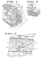
- Track assemblies 11, 12 include a plurality of articulated links 13 coupled in tandem to form an endless or cyclic "belt". Links 13 support track shoes 14 secured thereto by means of bolts 16.
- Vehicle 10 uses its tracks to demolish and compact a fill of materials such as earth and debris, rocks, refuse, etc.
- Each shoe 14 comprises substantially a rigid rectangular plate 17.
- the term "bottom” surface pertains to that surface which acts as a tread surface for engaging the ground as vehicle 10 is moved. It will be readily evident, however, that the "bottom” surface 19, when inverted, (as in Figures 4 and 5) becomes a "top” surface during a substantial portion of its cyclic travel.
- a relief opening 21 in the form of a relatively large trapezoidal shaped opening extends centrally through shoe
- Opening 2 1 is sufficiently large to readily release fill material outwardly therethrough so as to inhibit the buildup of compacted materials behind shoe 14.
- the leading or left-hand edge 19b curves slightly downwardly so as to slide under the trailing edge 19c of a shoe 14 preceding it in track assembly 11.
- the leading edge margin 24 of plate 17 serves to provide a closure between shoes disposed in tandem along track assembly 11. Accordingly, as the shoes 14 travel a horizontal stretch of their path, edge margin 24 will be disposed beneath trailing edge 19c of a preceding shoe 14.
- the remainder of the bottom surface of shoe 14 provides a substantial region for engaging the ground referred to herein as the "tread" surface.
- the region defined within the dimensions x, y comprises the tread surface.
- a drive sprocket 44 engages link pins 46 to move the track assembly.
- the sprocket points are aligned to pass directly beneath opening 21 whereby they can assist in urging impacted material out of opening 21.
- edges 19b and 19c of adjacent shoes move to open and close a gap therebetween. This action as well as that of the drive sprocket 44 causes impacted materials to be urged outwardly through opening 21.
- a pair of grouser blades 22, 23 carried from the bottom surface of shoe 14 protrude generally normal to the tread surface and respectively extend transversely of shoe 14 along a substantial part of the extent of the leading and trailing transverse edge margins, 26, 27 of tread surface x, y.
- Grouser blades 22, 23 are mutually offset laterally to opposite sides of the centerline of the path of movement of track shoes 14 for reasons described further below.
- bottom surface 19 carries a pair of demolition blades 28, 29 which also protrude generally normal to the region of tread surface x, y. Blades 28, 29 extend diagonally substantially in parallel relation respectively from the leading and trailing edge margins 26, 31 toward the trailing and leading edge margins 31 1 26 respectively for purposes of demolishing debris while permitting any impacted material emerging from opening 21 to freely leave the track.
- Grouser 22 includes a tapered fillet 22a which serves to strengthen plate 17 in the region of the leading edge 21 a of opening 21 and the openings (not shown) for bolts 32.
- the bolt holes and the elongate edge 21 cause the adjacent portion of plate 17 to be the weakest portion. This weakening of a leading portion of plate 17 has thereby been stiffened by the inclusion of the tapered fillet 22a.
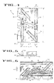
- Both of blades 22, 23 extend only part way across the full width, y, of shoe 14 and are mutually offset to opposite sides of the centerline of the path of its associated track.
- Each displacement 33, 34 ( Figure 4) respectively defined between the laterally inner ends of an associated grouser blade 22, 23 and a side edge 36, 37 of the rigid plate includes a gap 38, 39 respectively defined between the laterally inner end of an associated grouser blade and a portion of a demolition blade invading the plane of the grouser blade.
- Gaps 38, 39 serve to channel debris 42 away from shoe 14. Additional gaps or channels for debris to fall through are indicated at 38' and 39'.
- Demolition blades 28, 29 lie mainly behind an associated one of gaps 38, 39 in the path of fill materials 42 passing therethrough.
- Figure 6 represents a track shoe 14 moving upwardly in the direction of arrow 43 as the vehicle moves in a forward direction, i.e., as the track assembly is viewed from behind, impacted debris 42 in back of shoe 14 will be shaken loose by the relative movement between shoes 14 as they move around the end of their cyclic path as well as by the action of the drive sprocket 44.
- channels 39, 39' permit the loosened debris 42 to pass freely from shoe 14 by gravity.
- Channels 38, 38' perform this function when the track moves in a reverse direction.
- the tracks are designed to run "clean" so as to rid themselves of refuse and other fill materials rather quickly.
- use of the crawler style tracks further enhances this feature inasmuch as the shoes are drawn apart as they pass around the ends of the track. In this manner the tracks further tend to release material.
- This "track break” between consecutive shoes opens up a slot between shoes giving entrapped debris an opportunity to fall out.
- the vehicle described above achieves compaction by a substantially different technique than previously.
- shoe 1 4 includes means protruding therefrom to form a substantially continuous support beneath plate 17 in the region extending between grouser blades 22, 23.
- shoe 1 4 includes means protruding therefrom to form a substantially continuous support beneath plate 17 in the region extending between grouser blades 22, 23.
- one end 28a, 29a of each of demolition blades 28, 29 invades the plane defined by an associated one of the two grouser blades 22, 23 respectively.
- the other end 28b, 29b of each of blades 28, 29 extend substantially beyond an imaginary plane 41 common to each of the ends 28b, 29b, and disposed substantially to the path of an associated one of the tracks 11, 12. Plane 41 lies between the pair of grouser blades 22,23.
- the smoother ride created by the diagonal segments prevents the machine from rocking and falling from one grouser to the next and enhances the comfort of the operator as well as reducing metal fatigue and machine damage.
- shoes 1 4 can be employed together with conventional shoes of the type used on track-type tractors.
- shoe 14 can be al- temated with a standard shoe as desired at the expense of a commensurate loss in function and efficiency.
- tracks 11, 12 can be driven in opposite directions onto the debris and in this manner virtually “screw" the material into the ground.
Landscapes
- Engineering & Computer Science (AREA)
- Structural Engineering (AREA)
- Life Sciences & Earth Sciences (AREA)
- Paleontology (AREA)
- Soil Sciences (AREA)
- Environmental & Geological Engineering (AREA)
- General Life Sciences & Earth Sciences (AREA)
- Mining & Mineral Resources (AREA)
- Agronomy & Crop Science (AREA)
- Civil Engineering (AREA)
- General Engineering & Computer Science (AREA)
- Road Repair (AREA)
- Consolidation Of Soil By Introduction Of Solidifying Substances Into Soil (AREA)
- Soil Working Implements (AREA)
- Cleaning Of Streets, Tracks, Or Beaches (AREA)
- Vehicle Body Suspensions (AREA)
Priority Applications (1)
| Application Number | Priority Date | Filing Date | Title |
|---|---|---|---|
| AT85306692T ATE58567T1 (de) | 1984-09-21 | 1985-09-19 | Abbrechungs- und verdichtungsraupe und verbindung fuer ein raupenfahrzeug. |
Applications Claiming Priority (2)
| Application Number | Priority Date | Filing Date | Title |
|---|---|---|---|
| US65366184A | 1984-09-21 | 1984-09-21 | |
| US653661 | 1984-09-21 |
Publications (3)
| Publication Number | Publication Date |
|---|---|
| EP0179567A2 true EP0179567A2 (de) | 1986-04-30 |
| EP0179567A3 EP0179567A3 (en) | 1987-04-01 |
| EP0179567B1 EP0179567B1 (de) | 1990-11-22 |
Family
ID=24621820
Family Applications (1)
| Application Number | Title | Priority Date | Filing Date |
|---|---|---|---|
| EP85306692A Expired - Lifetime EP0179567B1 (de) | 1984-09-21 | 1985-09-19 | Abbrechungs- und Verdichtungsraupe und Verbindung für ein Raupenfahrzeug |
Country Status (6)
| Country | Link |
|---|---|
| EP (1) | EP0179567B1 (de) |
| JP (1) | JPS61113572A (de) |
| AT (1) | ATE58567T1 (de) |
| AU (2) | AU588546B2 (de) |
| CA (1) | CA1283679C (de) |
| DE (1) | DE3580649D1 (de) |
Cited By (1)
| Publication number | Priority date | Publication date | Assignee | Title |
|---|---|---|---|---|
| WO2013085757A1 (en) * | 2011-12-08 | 2013-06-13 | Ernie Freeman | Track pad |
Family Cites Families (4)
| Publication number | Priority date | Publication date | Assignee | Title |
|---|---|---|---|---|
| GB203617A (en) * | 1923-02-02 | 1923-09-13 | Bear Tractor Corp | Improvements in track chain construction for tractors |
| US2470801A (en) * | 1946-10-15 | 1949-05-24 | Ralph B Boltman | Tractor tread |
| US3355225A (en) * | 1966-01-04 | 1967-11-28 | Joy Mfg Co | Grouser configuration for track tread links |
| US4043610A (en) * | 1976-08-23 | 1977-08-23 | General Motors Corporation | Track shoe |
-
1985
- 1985-09-16 AU AU47478/85A patent/AU588546B2/en not_active Ceased
- 1985-09-19 EP EP85306692A patent/EP0179567B1/de not_active Expired - Lifetime
- 1985-09-19 DE DE8585306692T patent/DE3580649D1/de not_active Expired - Lifetime
- 1985-09-19 AT AT85306692T patent/ATE58567T1/de not_active IP Right Cessation
- 1985-09-20 JP JP60208551A patent/JPS61113572A/ja active Granted
- 1985-09-20 CA CA000491290A patent/CA1283679C/en not_active Expired - Lifetime
-
1989
- 1989-07-10 AU AU37985/89A patent/AU615317B2/en not_active Ceased
Cited By (3)
| Publication number | Priority date | Publication date | Assignee | Title |
|---|---|---|---|---|
| WO2013085757A1 (en) * | 2011-12-08 | 2013-06-13 | Ernie Freeman | Track pad |
| CN104039637A (zh) * | 2011-12-08 | 2014-09-10 | 厄尼·弗里曼 | 履带块 |
| CN104039637B (zh) * | 2011-12-08 | 2017-05-17 | 厄尼·弗里曼 | 履带块 |
Also Published As
| Publication number | Publication date |
|---|---|
| AU588546B2 (en) | 1989-09-21 |
| DE3580649D1 (de) | 1991-01-03 |
| ATE58567T1 (de) | 1990-12-15 |
| AU4747885A (en) | 1986-03-27 |
| JPS61113572A (ja) | 1986-05-31 |
| EP0179567A3 (en) | 1987-04-01 |
| CA1283679C (en) | 1991-04-30 |
| AU615317B2 (en) | 1991-09-26 |
| JPH0144552B2 (de) | 1989-09-28 |
| EP0179567B1 (de) | 1990-11-22 |
| AU3798589A (en) | 1989-10-19 |
Similar Documents
| Publication | Publication Date | Title |
|---|---|---|
| US4865400A (en) | Demolition and compaction track shoe and assembly for crawler vehicle | |
| US4750792A (en) | Demolition and compaction track shoe and assembly for crawler vehicle | |
| US3922106A (en) | Compaction wheel with traction and crushing characteristics | |
| US4991662A (en) | Land fill spreader blade assembly | |
| US4637753A (en) | Road planar having particle reducing means | |
| US7198333B1 (en) | Compactor cleat for land vehicles | |
| US4337586A (en) | Apparatus for the handling and conditioning of snow | |
| US5178484A (en) | Apparatus to prepare a road surface | |
| EP0629744A2 (de) | Verfahren und Anlage zur Untergrundsanierung einer Schotterbettung eines Gleises | |
| US4607799A (en) | Mobile stone crusher | |
| US3463063A (en) | Vehicular wheel for compacting sanitary fill | |
| US4482193A (en) | Roadable track assembly | |
| US5911373A (en) | Self-propelled rock crushing machine | |
| EP0179567B1 (de) | Abbrechungs- und Verdichtungsraupe und Verbindung für ein Raupenfahrzeug | |
| GB1586296A (en) | Combination low ground pressure low turning resistance and self-cleaning track shoe | |
| DD158116A5 (de) | Gleisbaumaschinen mit einer schotterbrett-raeum-und planiervorrichtung | |
| US4309126A (en) | Machine for separating concrete from steel | |
| US5482365A (en) | Rubber grousered track shoe | |
| DE19807677B4 (de) | Verfahrbare Gleisbaumaschine | |
| US4886124A (en) | Soil grading apparatus with sifting and transporting capability | |
| EP0957290A1 (de) | Verbindung zweier Enden eines Förderbandes | |
| US5772132A (en) | Self-propelled rock crushing machine | |
| JP3320873B2 (ja) | コンベヤを備えた路盤切削装置 | |
| CN216314003U (zh) | 用于履带式油莎豆收获机的平土分离装置 | |
| DE3819864C1 (en) | Mobile jaw crusher |
Legal Events
| Date | Code | Title | Description |
|---|---|---|---|
| PUAI | Public reference made under article 153(3) epc to a published international application that has entered the european phase |
Free format text: ORIGINAL CODE: 0009012 |
|
| AK | Designated contracting states |
Kind code of ref document: A2 Designated state(s): AT BE CH DE FR GB IT LI NL SE |
|
| PUAL | Search report despatched |
Free format text: ORIGINAL CODE: 0009013 |
|
| AK | Designated contracting states |
Kind code of ref document: A3 Designated state(s): AT BE CH DE FR GB IT LI NL SE |
|
| 17P | Request for examination filed |
Effective date: 19870713 |
|
| 17Q | First examination report despatched |
Effective date: 19881202 |
|
| GRAA | (expected) grant |
Free format text: ORIGINAL CODE: 0009210 |
|
| ITF | It: translation for a ep patent filed | ||
| AK | Designated contracting states |
Kind code of ref document: B1 Designated state(s): AT BE CH DE FR GB IT LI NL SE |
|
| REF | Corresponds to: |
Ref document number: 58567 Country of ref document: AT Date of ref document: 19901215 Kind code of ref document: T |
|
| REF | Corresponds to: |
Ref document number: 3580649 Country of ref document: DE Date of ref document: 19910103 |
|
| ET | Fr: translation filed | ||
| PLBE | No opposition filed within time limit |
Free format text: ORIGINAL CODE: 0009261 |
|
| STAA | Information on the status of an ep patent application or granted ep patent |
Free format text: STATUS: NO OPPOSITION FILED WITHIN TIME LIMIT |
|
| ITTA | It: last paid annual fee | ||
| 26N | No opposition filed | ||
| EAL | Se: european patent in force in sweden |
Ref document number: 85306692.6 |
|
| PGFP | Annual fee paid to national office [announced via postgrant information from national office to epo] |
Ref country code: SE Payment date: 19980820 Year of fee payment: 14 |
|
| PGFP | Annual fee paid to national office [announced via postgrant information from national office to epo] |
Ref country code: AT Payment date: 19980821 Year of fee payment: 14 |
|
| PGFP | Annual fee paid to national office [announced via postgrant information from national office to epo] |
Ref country code: NL Payment date: 19980825 Year of fee payment: 14 |
|
| PGFP | Annual fee paid to national office [announced via postgrant information from national office to epo] |
Ref country code: CH Payment date: 19981005 Year of fee payment: 14 |
|
| PG25 | Lapsed in a contracting state [announced via postgrant information from national office to epo] |
Ref country code: AT Free format text: LAPSE BECAUSE OF NON-PAYMENT OF DUE FEES Effective date: 19990919 |
|
| PG25 | Lapsed in a contracting state [announced via postgrant information from national office to epo] |
Ref country code: SE Free format text: THE PATENT HAS BEEN ANNULLED BY A DECISION OF A NATIONAL AUTHORITY Effective date: 19990929 |
|
| PG25 | Lapsed in a contracting state [announced via postgrant information from national office to epo] |
Ref country code: LI Free format text: LAPSE BECAUSE OF NON-PAYMENT OF DUE FEES Effective date: 19990930 Ref country code: CH Free format text: LAPSE BECAUSE OF NON-PAYMENT OF DUE FEES Effective date: 19990930 |
|
| PG25 | Lapsed in a contracting state [announced via postgrant information from national office to epo] |
Ref country code: NL Free format text: LAPSE BECAUSE OF NON-PAYMENT OF DUE FEES Effective date: 20000401 |
|
| EUG | Se: european patent has lapsed |
Ref document number: 85306692.6 |
|
| REG | Reference to a national code |
Ref country code: CH Ref legal event code: PL |
|
| NLV4 | Nl: lapsed or anulled due to non-payment of the annual fee |
Effective date: 20000401 |
|
| PGFP | Annual fee paid to national office [announced via postgrant information from national office to epo] |
Ref country code: FR Payment date: 20010831 Year of fee payment: 17 Ref country code: DE Payment date: 20010831 Year of fee payment: 17 |
|
| PGFP | Annual fee paid to national office [announced via postgrant information from national office to epo] |
Ref country code: GB Payment date: 20010904 Year of fee payment: 17 |
|
| PGFP | Annual fee paid to national office [announced via postgrant information from national office to epo] |
Ref country code: BE Payment date: 20010926 Year of fee payment: 17 |
|
| REG | Reference to a national code |
Ref country code: GB Ref legal event code: IF02 |
|
| PG25 | Lapsed in a contracting state [announced via postgrant information from national office to epo] |
Ref country code: GB Free format text: LAPSE BECAUSE OF NON-PAYMENT OF DUE FEES Effective date: 20020919 |
|
| PG25 | Lapsed in a contracting state [announced via postgrant information from national office to epo] |
Ref country code: BE Free format text: LAPSE BECAUSE OF NON-PAYMENT OF DUE FEES Effective date: 20020930 |
|
| BERE | Be: lapsed |
Owner name: *CARON COMPACTOR CY Effective date: 20020930 |
|
| PG25 | Lapsed in a contracting state [announced via postgrant information from national office to epo] |
Ref country code: DE Free format text: LAPSE BECAUSE OF NON-PAYMENT OF DUE FEES Effective date: 20030401 |
|
| GBPC | Gb: european patent ceased through non-payment of renewal fee |
Effective date: 20020919 |
|
| PG25 | Lapsed in a contracting state [announced via postgrant information from national office to epo] |
Ref country code: FR Free format text: LAPSE BECAUSE OF NON-PAYMENT OF DUE FEES Effective date: 20030603 |
|
| REG | Reference to a national code |
Ref country code: FR Ref legal event code: ST |