EP0178963A1 - Stabilisation system for inflatable rafts - Google Patents
Stabilisation system for inflatable rafts Download PDFInfo
- Publication number
- EP0178963A1 EP0178963A1 EP85401749A EP85401749A EP0178963A1 EP 0178963 A1 EP0178963 A1 EP 0178963A1 EP 85401749 A EP85401749 A EP 85401749A EP 85401749 A EP85401749 A EP 85401749A EP 0178963 A1 EP0178963 A1 EP 0178963A1
- Authority
- EP
- European Patent Office
- Prior art keywords
- stabilization system
- toroidal
- raft
- water
- Prior art date
- Legal status (The legal status is an assumption and is not a legal conclusion. Google has not performed a legal analysis and makes no representation as to the accuracy of the status listed.)
- Granted
Links
- 230000006641 stabilisation Effects 0.000 title claims abstract description 22
- XLYOFNOQVPJJNP-UHFFFAOYSA-N water Substances O XLYOFNOQVPJJNP-UHFFFAOYSA-N 0.000 claims abstract description 36
- 239000004744 fabric Substances 0.000 claims abstract description 6
- 238000011105 stabilization Methods 0.000 claims description 18
- 238000005192 partition Methods 0.000 claims description 6
- 238000005188 flotation Methods 0.000 claims description 2
- 238000007689 inspection Methods 0.000 claims description 2
- 230000017260 vegetative to reproductive phase transition of meristem Effects 0.000 claims 1
- 230000005540 biological transmission Effects 0.000 description 3
- 238000013016 damping Methods 0.000 description 3
- 230000000694 effects Effects 0.000 description 3
- 238000004873 anchoring Methods 0.000 description 2
- 238000004891 communication Methods 0.000 description 2
- 241000287107 Passer Species 0.000 description 1
- 238000007792 addition Methods 0.000 description 1
- 230000001627 detrimental effect Effects 0.000 description 1
- 230000009977 dual effect Effects 0.000 description 1
- 230000000977 initiatory effect Effects 0.000 description 1
- 238000012423 maintenance Methods 0.000 description 1
- 238000004519 manufacturing process Methods 0.000 description 1
- 239000000463 material Substances 0.000 description 1
- 238000012986 modification Methods 0.000 description 1
- 230000004048 modification Effects 0.000 description 1
- 238000004806 packaging method and process Methods 0.000 description 1
- 230000001105 regulatory effect Effects 0.000 description 1
- 230000002787 reinforcement Effects 0.000 description 1
- 230000003014 reinforcing effect Effects 0.000 description 1
- 238000007493 shaping process Methods 0.000 description 1
- 238000000638 solvent extraction Methods 0.000 description 1
- 230000008961 swelling Effects 0.000 description 1
- 239000004753 textile Substances 0.000 description 1
Images


Classifications
-
- B—PERFORMING OPERATIONS; TRANSPORTING
- B63—SHIPS OR OTHER WATERBORNE VESSELS; RELATED EQUIPMENT
- B63C—LAUNCHING, HAULING-OUT, OR DRY-DOCKING OF VESSELS; LIFE-SAVING IN WATER; EQUIPMENT FOR DWELLING OR WORKING UNDER WATER; MEANS FOR SALVAGING OR SEARCHING FOR UNDERWATER OBJECTS
- B63C9/00—Life-saving in water
- B63C9/08—Life-buoys, e.g. rings; Life-belts, jackets, suits, or the like
- B63C9/081—Life-buoys, e.g. rings; Life-belts, jackets, suits, or the like having compartments comprising elements which are filled with gas by deployment, e.g. sponge-like elements
-
- B—PERFORMING OPERATIONS; TRANSPORTING
- B63—SHIPS OR OTHER WATERBORNE VESSELS; RELATED EQUIPMENT
- B63B—SHIPS OR OTHER WATERBORNE VESSELS; EQUIPMENT FOR SHIPPING
- B63B39/00—Equipment to decrease pitch, roll, or like unwanted vessel movements; Apparatus for indicating vessel attitude
Definitions
- the present invention relates to stabilization systems for inflatable liferafts made up of a toroidal water bag fixed to the periphery of the raft under the lower flotation flange and under the bottom.
- toroidal water bag constituted by a toroidal chamber delimiting under the raft bottom a space open at its lower part.
- the interior wall of the chamber is pierced with openings allowing communication between the central space and the chamber, this communication being prevented in the opposite direction by flaps.
- Other openings, located on the outer wall of the chamber, allow water to enter and exit the chamber.
- the forces transmitted between the water bag and the structure of the raft can reach very high levels in heavy weather. If the raft is carried out, as is the case for rafts for aeronautical use, with light fabrics therefore limited in mechanical strength, a rupture between the water bag and the raft proper may occur. In addition, stress concentrations may occur at the level of the water passage holes, which necessitates reinforcements of these zones.
- the known stabilization device constituted by the water bag is more bulky in packaging than conventional devices. This is due to the use of waterproof coated fabrics and the use of rigid weights intended to facilitate deployment in the water of the toroidal chamber.
- the invention proposes to produce the toroidal chamber with a geometry making it possible to remove the rectangular edges and to receive a flexible ballast.
- the bottom of the toroidal pocket can have a cross-sectional shape in section, which makes it possible to eliminate the angular edges and to receive a flexible ballast allowing easy folding.
- the toroidal pocket can have a vertical interior partitioning, of limited height, which makes it possible, in connection with the continuous nets carried by the walls, to facilitate evacuation. part of the water in the pocket.
- provision may be made to equip the interior walls of the pocket with an inflatable frame.
- FIG. 1 and 2 there is shown schematically an inflatable raft comprising two superimposed inflatable tubes 1, 2, the upper tube 1 serving as a support for a flexible roof 3 and the lower tube 2 being integral with the bottom 4 of the raft.
- a water bag 5 made of flexible coated or uncoated waterproof fabric is fixed to the lower part of the tube 2.
- the bag 5, forming a toroidal chamber consists of two vertical walls 6, 7 connected together by a bottom 8 which presents in section an arc shape.
- the polygonal shape of the water pocket 5 is in agreement with that of the lower rod 2 of the raft.
- the vertical walls 6, 7 of the pocket 5 are each continued by a continuous orifice around the entire periphery of these walls, this orifice being constituted by a mesh, respectively 9, 10.
- Fastening elements 11 connect the pocket toroldale 5 to the structure of the raft that is to say lower auboudin 2 and the bottom 4.
- the pocket 5 has, from its base 8 to the orifices 9, 10, a partition 12.
- the number of partitions depends on the shape of the boat.
- Each partition 12 is fixed by its periphery to the walls of the toroidal pocket and a flexible textile link 13 ensures the attachment to the flange 2 by a flexible connection reinforcing the partition 12 in its middle.
- a hole 14 of suitable diameter allows emptying of the various compartments of the toroidal pocket 5 after lifting the boat without, however, in use, allowing the water to wobble from one compartment to the other.
- the external 9 and internal 10 connecting nets which provide the connection between the toroidal pocket 5 and the structure of the raft, distribute the forces evenly and make it possible to avoid stress concentrations.
- these nets act as a regulator by limiting the exchange of water between the pocket 5, the exterior and the central space 15 located under the bottom 4 of the raft. This results in effective damping of the transmission of water movements to the raft passengers.
- the bottom 8 of the pocket 5 is rounded, which simplifies manufacture and makes it possible to ballast the pocket with a flexible ballast (not shown in the drawing), for example lines of lead grains.
- the operation of the stabilization system is immediately understood from the above description.
- the weighted pocket 5 is deployed while the water penetrates through the meshes of the nets 9, 10 and fills this pocket.
- the raft In heavy and choppy sea the raft being subjected to movements, in particular vertical reciprocating, the surface of the nets 9, 10 makes it possible to eliminate a significant body of water during the upward movement of the boat, which leads to damping efforts increasing passenger comfort and particularly protecting the connection 11 of the pocket 5 on the float 2 of the raft from excessively high stresses.
- the pocket 5 fills up again.
- This frame consists of flexible tubing 16 made of coated fabric, plastic or other suitable gas-tight material.
- the frame is flexibly connected to the float (not shown in FIGS. 3 and 4) and at several points in the chamber 5. When the frame 16 inflates, it takes shape and, bearing on the float, it achieves almost immediate shaping of the pocket.
- the inflation of the frame can be controlled automatically. cally, by means of known systems, either from the inflation of the main floats of the boat, or from the simple contact of the boat with water.
- a bottle 17 containing a gas for example CO 2
- the bottle 17 contains a sufficient quantity of gas for supply the armature 16 at a pressure sufficient for the efficiency of the system, and the volume of this armature is provided as small as possible so that on the one hand there is no buoyancy detrimental to the good functioning of the system and, on the other hand, to allow its operation from a reduced capacity of the bottle 17.
- the control head 18 of the bottle 17 can be activated by a lever (not shown) to which one end of a halyard of sufficient strength is attached, the second end being fixed at a point on the boat which is not far away when that -this is folded.
- a lever not shown
- the length of the control halyard being constant, the extreme attachment points move away, which causes traction on the lever initiating the inflation of the frame 16.
- the control head 18 of the bottle 17 can also be activated by a pusher under the action of a spring previously compressed and held in place by an intermediate piece having the property of disintegrating under the action of water. We then understand that, as soon as the boat falls into the water, the inflation of the frame 16 is initiated.
- the maintenance of the toroidal pocket 5 is facilitated by providing for the fixing of this pocket to the raft structure by means of lacing strips 19, which can be replaced by any other suitable system allowing the standard exchange of the toroidal pocket 5.
- Inspection windows 20, closed by lacing strips or any other suitable device, are also provided on the vertical walls 6, 7 of the pocket 5.
Landscapes
- Engineering & Computer Science (AREA)
- Mechanical Engineering (AREA)
- Ocean & Marine Engineering (AREA)
- Chemical & Material Sciences (AREA)
- Combustion & Propulsion (AREA)
- Air Bags (AREA)
Abstract
Description
La présente invention concerne les systèmes de stabilisation pour radeau pneumatique de sauvetage oonstitués par une poche à eau de forme toroldale fixée à la périphérie du radeau sous le boudin de flottaison inférieur et sous le fond.The present invention relates to stabilization systems for inflatable liferafts made up of a toroidal water bag fixed to the periphery of the raft under the lower flotation flange and under the bottom.
Dans ce domaine, on a déjà proposé des systèmes de stabilisation par poche à eau toroidale constituée par une chambre toroïdale délimitant sous le fond de radeau un espace ouvert à sa partie inférieure. La paroi intérieure de la chambre est percée d'ouvertures permettant une communication entre l'espace central et la chambre, cette communication étant empêchée en sens inverse par des clapets. D'autres ouvertures, situées sur la paroi extérieure de la chambre, permettent à l'eau d'entrer et de sortir de la chambre.In this area, stabilization systems have already been proposed using a toroidal water bag constituted by a toroidal chamber delimiting under the raft bottom a space open at its lower part. The interior wall of the chamber is pierced with openings allowing communication between the central space and the chamber, this communication being prevented in the opposite direction by flaps. Other openings, located on the outer wall of the chamber, allow water to enter and exit the chamber.
Il s'ensuit la création d'un vide partiel sous le radeau conduisant à créer une force de résistance au mouvement de soulèvement du radeau hors de l'eau qui s'oppose par gros temps au risque de retournement du radeau en supprimant la possibilité au vent de passer sous le radeau et de le soulever.It follows the creation of a partial vacuum under the raft leading to create a force of resistance to the lifting movement of the raft out of the water which opposes in heavy weather the risk of overturning the raft by eliminating the possibility of wind to pass under the raft and to lift it.
Néanmoins, les efforts transmis entre la poche à eau et la structure du radeau peuvent atteindre par gros temps des niveaux très élevés. Si le radeau est réalisé, comme c'est le cas pour des radeaux à usage aéronautique, avec des tissus légers donc limités en tenue mécanique, une rupture entre la poche à eau et le radeau proprement dit risque de se produire. Par ailleurs, des concentrations d'effort peuvent se présenter au niveau des trous de passage de l'eau ce qui nécessite des renforcements de ces zones.However, the forces transmitted between the water bag and the structure of the raft can reach very high levels in heavy weather. If the raft is carried out, as is the case for rafts for aeronautical use, with light fabrics therefore limited in mechanical strength, a rupture between the water bag and the raft proper may occur. In addition, stress concentrations may occur at the level of the water passage holes, which necessitates reinforcements of these zones.
D'autre part, le dispositif de stabilisation connu constitué par la poche à eau est plus encombrant au conditionnement que les dispositifs classiques. Ceci est dû à l'emploi de tissus enduits étanches et à l'emploi de lests rigides destinés à faciliter le déploiement dans l'eau de la chambre toroldale.On the other hand, the known stabilization device constituted by the water bag is more bulky in packaging than conventional devices. This is due to the use of waterproof coated fabrics and the use of rigid weights intended to facilitate deployment in the water of the toroidal chamber.
La présente invention a pour objet d'éviter les inconvénients exposés ci-dessus et elle propose à cet effet un système de stabilisation pour radeaux pneumatiques dans lequel la liaison entre la chambre à eau toroïdale et l'embarcation est adaptée.:
- - de façon à répartir au maximum les efforts entre la chambre toroldale et la structure du radeau et à supprimer les concentrations de contraintes au droit des trous d'alimentation de la poche,
- - de façon à éviter un effet de succion trop important afin de créer un amortissement des mouvements relatifs du radeau par rapport à l'eau.
- - so as to distribute the forces as much as possible between the toroidal chamber and the structure of the raft and to eliminate the concentrations of stresses in line with the supply holes in the pocket,
- - so as to avoid an excessive suction effect in order to create a damping of the relative movements of the raft with respect to the water.
De plus, l'invention propose de réaliser la chambre toroldale avec une géométrie permettant de supprimer les arêtes rectangulaires et de recevoir un lest souple.In addition, the invention proposes to produce the toroidal chamber with a geometry making it possible to remove the rectangular edges and to receive a flexible ballast.
Selon l'invention, les parois verticales extérieure et intérieure de la poche toroldale présentent chacune, sur tout son pourtour, un orifice continu constitué par une résille. Ces résilles externe et interne ont un double rôle :
- - un rôle mécanique en assurant la liaison entre la poche et la structure du radeau, la résille répartissant de façon homogène les efforts et évitant les concentrations de contraintes,
- - un rôle régulateur en limitant les échanges d'eau entre la poche, l'extérieur et l'espace central situé sous le fond du radeau, sans toutefois emprisonner l'eau située dans l'espace central. Il en résulte un ancrage moins étroit du radeau à la surface de l'eau, ce qui permet d'amortir la transmission des mouvements de l'eau aux passagers du radeau, et également un effet de coupe vent efficace bien que le vent puisse passer à travers les mailles de la résille.
- - a mechanical role by ensuring the connection between the pocket and the structure of the raft, the fishnet distributing the forces homogeneously and avoiding stress concentrations,
- - a regulatory role by limiting the exchange of water between the pocket, the exterior and the central space located under the bottom of the raft, without however trapping the water located in the central space. This results in a less tight anchorage of the raft on the surface of the water, which makes it possible to dampen the transmission of the movements of the water to the passengers of the raft, and also an effective windbreak effect although the wind can pass through the mesh of the fishnet.
Avantageusement, le fond de la poche toroïdale peut présenter en section une forme en arc de cercle, ce qui permet de supprimer les arêtes angulaires et de recevoir un lest souple autorisant un pliage facile. Egalement, la poche toroldale peut présenter un cloisonnement intérieur vertical, de hauteur limitée, qui permet en liaison avec les résilles continues portées par les parois de faciliter l'évacuation d'une partie de l'eau contenue dans la poche.Advantageously, the bottom of the toroidal pocket can have a cross-sectional shape in section, which makes it possible to eliminate the angular edges and to receive a flexible ballast allowing easy folding. Also, the toroidal pocket can have a vertical interior partitioning, of limited height, which makes it possible, in connection with the continuous nets carried by the walls, to facilitate evacuation. part of the water in the pocket.
Pour faciliter le déploiement de la poche toroïdale, lors du gonflage du radeau, on peut prévoir d'équiper les parois intérieures de la poche d'une armature gonflable.To facilitate the deployment of the toroidal pocket, during inflation of the raft, provision may be made to equip the interior walls of the pocket with an inflatable frame.
On peut aussi prévoir de relier les parois verticales de la poche toroïdale à la structure du radeau par un moyen de liaison démontable tel par exemple qu'une bande de laçage.One can also provide for connecting the vertical walls of the toroidal pocket to the structure of the raft by a removable connection means such as for example a lacing strip.
Pour bien faire comprendre le système de stabilisation selon l'invention on en décrira ci-après, à titre d'exemple sans caractère limitatif, une forme d'exécution préférée et des variantes, en référence au dessin schématique annexé dans lequel :
- la figure 1 est une vue en élévation d'un radeau pneumatique équipé d'un système de stabilisation selon l'invention ;
- la figure 2 est, à plus grande échelle, une vue de détail de la figure 1 en coupe verticale montrant plus particulièrement le système de stabilisation ;
- la figure 3 est une vue perspective, avec arrachement partiel, d'une variante de chambre à eau toroldale équipée d'une armature gonflable assurant le déploiement de cette chambre ;
- la figure 4 est une vue partielle en coupe verticale de la chambre toroïdale de la figure 3 ;
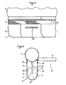
- la figure 5 est une vue partielle en élévation d'un radeau pneumatique équipé d'une autre variante de chambre toroïdale amovible ; et
- la figure 6 est une vue schématique en coupe verticale de la figure 5.
- Figure 1 is an elevational view of a pneumatic raft equipped with a stabilization system according to the invention;
- Figure 2 is, on a larger scale, a detail view of Figure 1 in vertical section showing more particularly the stabilization system;
- Figure 3 is a perspective view, partially broken away, of a variant of toroidal water chamber equipped with an inflatable frame ensuring the deployment of this chamber;
- Figure 4 is a partial view in vertical section of the toroidal chamber of Figure 3;
- FIG. 5 is a partial elevation view of a pneumatic raft fitted with another variant of a removable toroidal chamber; and
- FIG. 6 is a schematic view in vertical section of FIG. 5.
En référence aux figures 1 et 2, on a schématisé un radeau pneumatique comprenant deux boudins gonflables superposés 1, 2, le boudin supérieur 1 servant de support pour un toit souple 3 et le boudin inférieur 2 étant solidaire du fond 4 du radeau. Une poche à eau 5 en tissu souple imperméable enduit ou non enduit est fixée à la partie inférieure du boudin 2. La poche 5, formant une chambre de forme toroïdale, est constituée de deux parois verticales 6, 7 reliées ensemble par un fond 8 qui présente en section une forme en arc de cercle. En plan, la forme polygonale de la poche à eau 5 est en concordance avec celle du boudin inférieur 2 du radeau.Referring to Figures 1 and 2, there is shown schematically an inflatable raft comprising two superimposed
Vers le haut, les parois verticales 6, 7 de la poche 5 se continuent chacune par un orifice continu sur tout le pourtour de ces parois, cet orifice étant constitué par une résille, respectivement 9, 10. Des éléments de fixation 11 relient la poche toroldale 5 à la structure du radeau c'est-à-dire auboudin inférieur 2 et au fond 4.Upwards, the
La poche 5 comporte, de sa base 8 jusqu'aux orifices 9, 10, un cloisonnement 12. Le nombre de cloisons dépend de la forme de l'embarcation. Chaque cloison 12 est fixée par son pourtour aux parois de la poche toroïdale et un lien textile souple 13 assure la fixation au boudin 2 par une liaison souple renforçant la cloison 12 en son milieu. Au bas de chaque cloison 12, un trou 14 de diamètre convenable permet une vidange des différents compartiments de la poche toroldale 5 après relevage de l'embarcation sans cependant, en utilisation, permettre un ballottement de l'eau d'un compartiment à l'autre.The
Les résilles de liaison externe 9 et interne 10, qui assurent la liaison entre la poche toroïdale 5 et la structure du radeau, répartissent de façon homogène les efforts et permettent d'éviter les concentrations de contraintes. De plus, ces résilles agissent comme un régulateur en limitant les échanges d'eau entre la poche 5, l'extérieur et l'espace central 15 situé sous le fond 4 du radeau. Il en résulte un amortissement efficace de la transmission des mouvements de l'eau aux passagers du radeau.The external 9 and internal 10 connecting nets, which provide the connection between the
Le fond 8 de la poche 5 est arrondi, ce qui simplifie la fabrication et permet d'effectuer le lestage de la poche par un lest souple (non représenté au dessin), par exemple des lignes de grains de plomb.The
Le fonctionnement du système de stabilisation se comprend immédiatement d'après la description qui précède. Pendant la phase de gonflement de la structure du radeau, la poche lestée 5 se déploie tandis que l'eau pénètre à travers les mailles des résilles 9, 10 et remplit cette poche.The operation of the stabilization system is immediately understood from the above description. During the swelling phase of the raft structure, the
L'air emprisonné dans l'espace central 15 sous le fond 4 du radeau tend, sous l'effet du poids des passagers, à s'éliminer vers l'extérieur a travers les résilles et permet ainsi l'ancrage correct du radeau sur la surface de l'eau.The air trapped in the
Par mer forte et hachée le radeau étant soumis à des mouvements, en particulier verticaux alternatifs, la surface des résilles 9, 10 permet d'éliminer une masse d'eau significative lors du mouvement montant de l'embarcation, ce qui conduit à un amortissement des efforts augmentant le confort des passagers et protégeant particulièrement la liaison 11 de la poche 5 sur le flotteur 2 du radeau de contraintes trop élevées. Lors de la descente du radeau, la poche 5 se remplit à nouveau.In heavy and choppy sea the raft being subjected to movements, in particular vertical reciprocating, the surface of the
Selon une variante représentée aux figurés 3 et 4 on assure, pendant la phase de gonflement de la structure du radeau, un déploiement actif de la chambre toroidale 5. En effet, en plus du rôle d'ancrage en vue d'empêcher le retournement de l'embarcation, la poche à eau a un autre rôle important qui est de limiter la dérive de l'embarcation sous l'action du vent, en particulier lors d'un naufrage au moment de la mise à l'eau de l'embarcation (bien que celle-ci soit attachée à l'aéronef naufragé, cet amarrage peut céder sous l'action du vent ou du fait que l'appareil naufragé sombre avant que ses passagers aient pu embarquer à bord de l'embarcation de sauvetage qui se trouve ainsi libérée) ou lorsque l'embarcation de sauvetage est parachutée à des naufragés.According to a variant shown in FIGS. 3 and 4, active deployment of the
Dans le cas d'une poche à eau qui se remplit sous la simple action du lest, le remplissage même partiel peut prendre un certain temps d'autant que l'embarcation est inoccupée Celle-ci peut en conséquence dériver fortement durant ce laps de temps, rendant son accès d'autant plus difficile, voir impossibleIn the case of a water bag which fills under the simple action of the ballast, even partial filling can take a certain time as long as the boat is unoccupied This can consequently drift sharply during this period of time , making access all the more difficult, or even impossible
Le déploiement actif de la chambre toroidale 5, palliant cet inconvénient, s'obtient au moyen d'une armature gonflable disposée à l'intérieur de cette chambre. Cette armature est constituée par une tuyauterie souple 16 en tissu enduit, en matière plastique ou autre matériau approprié étanche aux gaz. L'armature est reliée de façon souple au flotteur (non représenté aux figures 3 et 4) et à plusieurs points de la chambre 5. Lorsque l'armature 16 se gonfle, elle se met en forme et, prenant appui sur le flotteur, elle réalise la mise en forme pratiquement immédiate de la poche.The active deployment of the
Le gonflage de l'armature peut être commandé automatiquement, au moyen de systèmes connus, soit à partir du gonflement des flotteurs principaux de l'embarcation, soit à partir du simple contact de l'embarcation avec l'eau. A cet effet, une bouteille 17 contenant un gaz (par exemple du CO2) est disposée dans la poche à eau 5 et sa tête dé commande 18 est reliée à l'armature gonflable 16. La bouteille 17 contient une quantité suffisante de gaz pour alimenter l'armature 16 à une pression suffisante pour l'efficacité du système, et le volume de cette armature est prévu aussi petit que possible de manière d'une part à ce qu'il n'y ait pas une flottabilité préjudiciable à la bonne marche du système et, d'autre part, à permettre son fonctionnement à partir d'une capacité réduite de la bouteille 17.The inflation of the frame can be controlled automatically. cally, by means of known systems, either from the inflation of the main floats of the boat, or from the simple contact of the boat with water. For this purpose, a
La tête de commande 18 de la bouteille 17 peut être activée par un levier (non représenté) auquel on attache une extrémité d'une drisse de résistance suffisante, la seconde extrémité étant fixée en un point de l'embarcation qui est peu éloigné lorsque celle-ci est pliée. Lors du gonflement de l'embarcation, la longueur de la drisse de commande étant constante, les points d'attache extrêmes s'éloignent ce qui provoque une traction sur le levier initiant le gonflage de l'armature 16.The control head 18 of the
La tête de commande 18 de la bouteille 17 peut aussi être activée par un poussoir sous l'action d'un ressort préalablement comprimé et maintenu en place par une pièce intermédiaire ayant la propriété de se désagréger sous l'action de l'eau. On comprend alors que, dès que l'embarcation tombe à l'eau, le gonflage de l'armature 16 est initié.The control head 18 of the
Selon une autre variante, représentée aux figures 5 et 6, on facilite la maintenance de la poche toroidale 5 en prévoyant la fixation de cette poche à la structure de radeau au moyen de bandes de laçage 19, pouvant être remplacées par tout autre système adéquat permettant l'échange standard de la poche toroldale 5. Des fenêtres de visite 20, fermées par bandes de laçage ou tout autre dispositif convenable, sont également prévues sur les parois verticales 6, 7 de la poche 5.According to another variant, represented in FIGS. 5 and 6, the maintenance of the
On comprendra que la description ci-dessus a été donnée à simple titre d'exemple, sans caractère limitatif, et que des adjonctions ou des modifications constructives pourraient y être apportées sans sortir du cadre de l'invention définie par les revendications qui suivent.It will be understood that the above description has been given by way of example, without limitation, and that additions or constructive modifications could be made to it. be made without departing from the scope of the invention defined by the claims which follow.
Claims (10)
Applications Claiming Priority (2)
| Application Number | Priority Date | Filing Date | Title |
|---|---|---|---|
| FR8413830A FR2570047B1 (en) | 1984-09-10 | 1984-09-10 | IMPROVED STABILIZATION SYSTEM FOR PNEUMATIC RAILS |
| FR8413830 | 1984-09-10 |
Publications (2)
| Publication Number | Publication Date |
|---|---|
| EP0178963A1 true EP0178963A1 (en) | 1986-04-23 |
| EP0178963B1 EP0178963B1 (en) | 1988-02-24 |
Family
ID=9307551
Family Applications (1)
| Application Number | Title | Priority Date | Filing Date |
|---|---|---|---|
| EP19850401749 Expired EP0178963B1 (en) | 1984-09-10 | 1985-09-09 | Stabilisation system for inflatable rafts |
Country Status (3)
| Country | Link |
|---|---|
| EP (1) | EP0178963B1 (en) |
| DE (1) | DE3561641D1 (en) |
| FR (1) | FR2570047B1 (en) |
Cited By (2)
| Publication number | Priority date | Publication date | Assignee | Title |
|---|---|---|---|---|
| US9573666B2 (en) | 2014-06-17 | 2017-02-21 | Zodiac Aerosafety Systems | Longitudinal scoops for rolling stability |
| KR101803555B1 (en) * | 2016-08-12 | 2017-11-30 | 장지환 | Not upside down tube |
Citations (3)
| Publication number | Priority date | Publication date | Assignee | Title |
|---|---|---|---|---|
| US3449777A (en) * | 1966-05-24 | 1969-06-17 | Hosoya Kako Co Ltd | Automatic inflating floating device |
| US4065888A (en) * | 1976-03-19 | 1978-01-03 | Reinhard Hans Napierski | Fluid inflatable spatially expandable hollow body construction |
| FR2416160A1 (en) * | 1978-02-02 | 1979-08-31 | Switlik Richard | LIFE RAFT |
-
1984
- 1984-09-10 FR FR8413830A patent/FR2570047B1/en not_active Expired
-
1985
- 1985-09-09 EP EP19850401749 patent/EP0178963B1/en not_active Expired
- 1985-09-09 DE DE8585401749T patent/DE3561641D1/en not_active Expired
Patent Citations (3)
| Publication number | Priority date | Publication date | Assignee | Title |
|---|---|---|---|---|
| US3449777A (en) * | 1966-05-24 | 1969-06-17 | Hosoya Kako Co Ltd | Automatic inflating floating device |
| US4065888A (en) * | 1976-03-19 | 1978-01-03 | Reinhard Hans Napierski | Fluid inflatable spatially expandable hollow body construction |
| FR2416160A1 (en) * | 1978-02-02 | 1979-08-31 | Switlik Richard | LIFE RAFT |
Cited By (2)
| Publication number | Priority date | Publication date | Assignee | Title |
|---|---|---|---|---|
| US9573666B2 (en) | 2014-06-17 | 2017-02-21 | Zodiac Aerosafety Systems | Longitudinal scoops for rolling stability |
| KR101803555B1 (en) * | 2016-08-12 | 2017-11-30 | 장지환 | Not upside down tube |
Also Published As
| Publication number | Publication date |
|---|---|
| DE3561641D1 (en) | 1988-03-31 |
| EP0178963B1 (en) | 1988-02-24 |
| FR2570047B1 (en) | 1989-12-15 |
| FR2570047A1 (en) | 1986-03-14 |
Similar Documents
| Publication | Publication Date | Title |
|---|---|---|
| AU2001263414B2 (en) | Automatic inflating boat flotation device | |
| CA2490729C (en) | Inflatable vessel for loading/unloading and transport of floating cargo | |
| CA2370052C (en) | Floating inflatable pneumatic device, in particular an inflatable survival raft, equipped with a venturi-based inflation mechanism | |
| EP0178963B1 (en) | Stabilisation system for inflatable rafts | |
| FR2596613A1 (en) | Assembly for raising aquatic animals and, more particularly, fish | |
| EP0058626B1 (en) | Stabilizing device for a dinghy | |
| EP1449763B1 (en) | Method and installation of subsea effluent pollution recovery from a sunken tanker by using multiple shuttle tanks | |
| EP0069091A2 (en) | Self inflatable life boat equipped with a sailing rig | |
| WO2001083293A1 (en) | Automatic underwater breathing membrane with integrated manual recharge | |
| FR2569651A1 (en) | FLOAT DEVICES FOR AIRCRAFT LANDING GEARS AND LANDING GEAR EQUIPPED WITH SUCH A DEVICE | |
| EP2582572B1 (en) | Semi-rigid craft, the buoyancy of which is adjustable | |
| FR2988371A1 (en) | Stage beacon for use in scuba diving, has ballast forming application envelope that is ready to contain buoy, rope rolled up around buoy, and fastener system ensuring maintenance of ballast in tubular confrontation around buoy and rope | |
| EP0867358B1 (en) | High-capacity liferaft | |
| FR2809601A1 (en) | Combined back pack and flotation aid, for carrying belongings while swimming, comprises liquid-tight bag fitted with sealable nozzle, allowing it to be inflated | |
| WO2009016273A2 (en) | Rescue device forming a craft | |
| FR2813579A1 (en) | Submersible mooring device with deflation means comprises mooring line, submersible body and compressed air generator; when filled with gas body rises to surface and after time lapse valve opens and gas expelled | |
| FR2780022A1 (en) | PNEUMATIC CRAFT, ESPECIALLY LIFE RAFT | |
| EP1186528A1 (en) | Submersible mooring device provided with own deflation means | |
| FR2659099A1 (en) | IMPROVEMENTS IN AUTOMATIC AIR INJECTION SYSTEMS USED IN WATER-CLOSETS HYDROPNEUMATIC CISTERN DISCHARGE. | |
| FR2862042A1 (en) | Flotation unit for craft, has flexible and water-proof body provided with frame-work formed by series of peripheral rings, and cap that is integrated with upper part and opened to drive flotation unit towards top | |
| FR2686308A1 (en) | Float intended for supporting an submerged cable at a determined depth, especially in oyster cultivation installations | |
| EP0927681A1 (en) | Automatic self-bailing apparatus for boat, particularly for a liferaft | |
| GB2167530A (en) | Valve | |
| EP1900626A1 (en) | Arrangement of the floats in a rigid-hull inflatable boat and boat equipped with same | |
| FR2813578A1 (en) | Submersible mooring device with deflation means comprises mooring line, submersible body and compressed air generator; when filled with gas body rises to surface and after time lapse valve opens and gas expelled |
Legal Events
| Date | Code | Title | Description |
|---|---|---|---|
| PUAI | Public reference made under article 153(3) epc to a published international application that has entered the european phase |
Free format text: ORIGINAL CODE: 0009012 |
|
| AK | Designated contracting states |
Kind code of ref document: A1 Designated state(s): DE GB IT |
|
| 17P | Request for examination filed |
Effective date: 19860819 |
|
| 17Q | First examination report despatched |
Effective date: 19870507 |
|
| RAP1 | Party data changed (applicant data changed or rights of an application transferred) |
Owner name: AERAZUR |
|
| GRAA | (expected) grant |
Free format text: ORIGINAL CODE: 0009210 |
|
| AK | Designated contracting states |
Kind code of ref document: B1 Designated state(s): DE GB IT |
|
| REF | Corresponds to: |
Ref document number: 3561641 Country of ref document: DE Date of ref document: 19880331 |
|
| ITF | It: translation for a ep patent filed | ||
| GBT | Gb: translation of ep patent filed (gb section 77(6)(a)/1977) | ||
| PLBE | No opposition filed within time limit |
Free format text: ORIGINAL CODE: 0009261 |
|
| STAA | Information on the status of an ep patent application or granted ep patent |
Free format text: STATUS: NO OPPOSITION FILED WITHIN TIME LIMIT |
|
| 26N | No opposition filed | ||
| ITTA | It: last paid annual fee | ||
| PGFP | Annual fee paid to national office [announced via postgrant information from national office to epo] |
Ref country code: GB Payment date: 19960912 Year of fee payment: 12 |
|
| PGFP | Annual fee paid to national office [announced via postgrant information from national office to epo] |
Ref country code: DE Payment date: 19961001 Year of fee payment: 12 |
|
| PG25 | Lapsed in a contracting state [announced via postgrant information from national office to epo] |
Ref country code: GB Free format text: LAPSE BECAUSE OF NON-PAYMENT OF DUE FEES Effective date: 19970909 |
|
| GBPC | Gb: european patent ceased through non-payment of renewal fee |
Effective date: 19970909 |
|
| PG25 | Lapsed in a contracting state [announced via postgrant information from national office to epo] |
Ref country code: DE Free format text: LAPSE BECAUSE OF NON-PAYMENT OF DUE FEES Effective date: 19980603 |