EP0177159B1 - Hosiery toe closing method and apparatus - Google Patents
Hosiery toe closing method and apparatus Download PDFInfo
- Publication number
- EP0177159B1 EP0177159B1 EP85306007A EP85306007A EP0177159B1 EP 0177159 B1 EP0177159 B1 EP 0177159B1 EP 85306007 A EP85306007 A EP 85306007A EP 85306007 A EP85306007 A EP 85306007A EP 0177159 B1 EP0177159 B1 EP 0177159B1
- Authority
- EP
- European Patent Office
- Prior art keywords
- layers
- blank
- layer
- displacement
- hose
- Prior art date
- Legal status (The legal status is an assumption and is not a legal conclusion. Google has not performed a legal analysis and makes no representation as to the accuracy of the status listed.)
- Expired
Links
- 238000000034 method Methods 0.000 title claims description 36
- 238000009958 sewing Methods 0.000 claims abstract description 9
- 238000006073 displacement reaction Methods 0.000 claims description 52
- 238000005304 joining Methods 0.000 claims description 21
- 238000007493 shaping process Methods 0.000 claims description 2
- 230000000452 restraining effect Effects 0.000 claims 1
- 239000004744 fabric Substances 0.000 abstract description 25
- 238000004826 seaming Methods 0.000 abstract description 17
- 210000003371 toe Anatomy 0.000 description 108
- 230000007246 mechanism Effects 0.000 description 31
- 238000004519 manufacturing process Methods 0.000 description 6
- 238000009940 knitting Methods 0.000 description 4
- 239000002699 waste material Substances 0.000 description 4
- 230000006978 adaptation Effects 0.000 description 3
- 238000011144 upstream manufacturing Methods 0.000 description 3
- 230000009471 action Effects 0.000 description 2
- 230000000694 effects Effects 0.000 description 2
- 210000002683 foot Anatomy 0.000 description 2
- 239000000463 material Substances 0.000 description 2
- 238000009966 trimming Methods 0.000 description 2
- 239000000969 carrier Substances 0.000 description 1
- 238000010276 construction Methods 0.000 description 1
- 239000006263 elastomeric foam Substances 0.000 description 1
- 230000004048 modification Effects 0.000 description 1
- 238000012986 modification Methods 0.000 description 1
- 230000008569 process Effects 0.000 description 1
- 238000012163 sequencing technique Methods 0.000 description 1
- 238000003466 welding Methods 0.000 description 1
Images


Classifications
-
- D—TEXTILES; PAPER
- D05—SEWING; EMBROIDERING; TUFTING
- D05B—SEWING
- D05B23/00—Sewing apparatus or machines not otherwise provided for
- D05B23/007—Sewing units for assembling parts of knitted panties or closing the stocking toe part
- D05B23/009—Toe closers
Definitions
- the present invention relates to a hosiery toe closing method and apparatus.
- the invention concerns the toe closing of socks.
- Stockings or pantihose could be toe closed by means of this invention.
- hosiery is knitted in a tubular form. One end of each tube blank has to be closed in some way, to form the toe end. Two toe closing techniques are in general use. These techniques are diagrammatically illustrated in the accompanying Fig. 1(a) to (d) to which reference is now directed.
- One technique involves reciprocating the knitting machine during the knitting operation to form what is known as a reciprocated toe or pouch P, see Fig. 1a, b.
- a reciprocated toe or pouch P see Fig. 1a, b.
- the confronting knit edges form the "looper line” and have to be seamed together to finish the hose toe.
- the closure is usually effected by automatic looper line closing machines or by a simple overlock sewing machine, to form the seam S. This technique is sometimes referred to as "looper line" toe closing.
- the second technique is to knit a straight tubular hose blank toe and to close it by hand seaming or by automatic machines such as the Detexomat (RTM) Speedomatic (RTM) half hose toe closer.
- the hose blank is disposed in a laid-flat condition, clamped along the intended seam line S (see Fig. Ic, d) and then moved past the seamer, e.g. an overlock machine, to form the curved seam S.
- the knitted material T is waste and is trimmed off during or after seaming.
- the alternative technique is well established, especially in the manufacture of conventional ladies stockings and pantihose. Excellent production rates are attained.
- the technique is not entirely suited to sock production, however. Apart from the waste factor, there is a drawback in that the seam may not be as comfortable as desired.
- the seam S which is somewhat bulky, lies across the ends of the wearer's toes where it may cause some discomfort.
- the seam should be above the wearer's toes or beneath them, in the hollow between the toes and the ball of the foot.
- the standard toe closing technique cannot readily emulate the looper line technique in so locating the seam.
- the present invention aims to achieve production rates approaching those of the conventional toe closing technique while obtaining seams or joins akin in location to those produced by the looper line technique.
- the seam or join can be caused to adopt an over-foot or under-foot position simply and of its own accord. Actual seaming or joining can be carried out along a straight line path or along a chosen curve if a deeper or shallower toe end were required, for instance.
- a method for closing the toe of a tubular hose blank comprising the steps of:
- apparatus for closing the toe of a tubular hose blank comprising means for arranging a toe end of the blank in a flattened condition defining two juxtaposed layers and means for joining the layers along a predetermined line across the blank, characterised by means for displacing at least one of the layers longitudinally of the blank to establish a relative mutual displacement between the layers, and by the apparatus being arranged to maintain the said displacement while the layers are joined by the joining means.
- a movable clamping means can be employed to convey the hose past means for joining the layers, thereby to generate the toe-closing join, so long as the mutual displacement of the layers is preserved during the movement.
- Suitable clamping means are known and are disclosed in our patents GB-B-1,039,104; GB-B-1,501,869; GB-B-1,577,758 and GB-B-2,074,203.
- the join can be formed along a line of predetermined shape which may be linear or curved.
- Apparatus featuring such clamping means can further comprise a hose blank carrier and loading means for the clamping means, the loading means being operable to take hold of the toe end of the blank on the carrier, to convey the toe end to the clamping means and to arrange the toe end in the flattened condition by stretching it laterally, and at the clamping means are the displacing means which are- operable to establish the said displacement before the clamping means clamp the two juxtaposed and mutually displaced layers.
- the toe-closing join will preferably be made by sewing, e.g. overlock sewing. Other joining methods could be adopted in appropriate cases, e.g. ultrasonic welding.
- One apparatus according to the present invention comprises:
- Blanks to be toe closed by the apparatus need no reciprocated toe or pouch and hence the knitting thereof is simplified.
- the apparatus can conveniently comprise an adaptation of known types of toe closer.
- the preferred hose carrier or mounting means comprises a pair of spaced-apart, flat blades or fingers. They may be movable apart to stretch the hose toe end laterally to establish the laid-flat condition.
- the blades can be associated with a suction tube for everting the hose blank.
- a holding means serves to immobilise a part or parts of the blank toe end while the displacing means acts on one of said layers and thereby establishes the said mutual displacement.
- the holding means may thereafter disengage from the toe end.
- the displacement means can comprise a reciprocally-movable element engageable with the said second layer, said element being disengageable therefrom after executing a displacing stroke when the clamp has gripped the toe end.
- the preferred clamping means comprises an endless flexible belt and a cooperating support between which the hose toe end is gripped, the belt being movable to advance the toe end across the support past the seamer.
- the clamp comprises belt-shaping means which enable the belt to grip the toe end along a predetermined linear or curvilinear line corresponding to the configuration of a predetermined seam line.
- the clamp could be omitted, where the toe closer has the mounting means supported to move past the joining means appropriately for the latter to join the layers of the passing toe end.
- the means to displace the layers relative to one another will move in step with the mounting means to maintain the mutual displacement while joining proceeds.
- the present invention also provides apparatus for closing the toe of a tubular hose blank comprising a hose blank carrier which serves to arrange the toe end of a hose blank carried thereby in a flattened condition, the carrier being movable to convey the two juxtaposed layers past the joining means for the latter to join them along the said line, and the displacing means are movable with the carrier and, after establishing the said displacement, the displacing means continue to maintain the displacement until after the two layers are joined.
- FIGs. 2(a) to (e) conveniently show the steps of our preferred method.
- a tubular hose blank H, or at least the toe end portion 10 thereof, is first placed in a laid-flat condition. This condition is most readily attained by laterally stretching the blank H, for example by placing it on a suitably dimensioned flat form, not shown.
- first and second layers 11, 12 of the hose fabric closely confront one another.
- part of the toe end e.g. the free end 14 of layer 11 is restrained from moving and layer 12 is pulled or pushed longitudinally in the direction A away from the end 14 of layer 11.
- the corresponding free end of layer 12 is drawn backwardly from end 14 and assumes a curved form as shown.
- an effective surplusage 15 of loose hose fabric is created or accumulated in layer 12.
- the distortion of the fabric sets up a complex state of tension in the two layers 11, 12.
- the relative displacement between layers 11, 12 determines how much surplusage 15 is accumulated.
- the next step involves securing the layers so as to maintain the said displacement, e.g. by clamping them together adjacent the intended seam line SL.
- Seam line SL as illustrated is linear, but it could be curved. Clamping of the layers has to preserve the mutual displacement until the required seam has been generated.
- the fourth step of the method accomplishes seaming along line SL by conveying the hose toe end past a seamer, with its layers 11, 12 still retaining their mutual displacement.
- the seamer is preferably a known sewing and trimming machine.
- the seamer generates the seam S as the toe end passes thereby and trims away waste.
- the waste comprises fabric to the right of the seam line SL, as viewed in Fig. 2(a).
- the hose toe can be visualised in side elevation as shown in Fig. 2(c).
- the seam S extends transversely of the blank H and is at the extreme end thereof.
- the loose surplusage 15 is still located in layer 12 rearwardly of the seam S.
- its fabric Upon releasing the hose from the laid-flat condition, its fabric will relax of its own accord and commence to redistribute itself.
- the surplusage 15 will move towards the hose toe end portion and the seam S will move towards an under- or over-foot position, see Fig. 2(d).
- Fig. 2(e) illustrates the resulting toe closed hose as seen from the side.
- the toe portion 16 is formed by the surplusage 15.
- the actual seam S will be arcuate even though it may be sewn along a straight seam line SL.
- the tubular blank H As the tubular blank H is knitted, its rows or courses of stitches run helically. When the blank is in the laid-flat condition, these courses extend transversely, to all intents and purposes. See Fig. 3(a), the courses being indicated by reference 18. Upon displacing one layer 12 relative to the other layer 11, the courses 18 in layer 12 become arcuately distorted, see Fig. 3(b), when the surplusage 15 is created. If the seam S is generated along a straight seam line and the laid-flat condition is thereafter removed, the courses will straighten towards their original configuration and the seam will take on a curved form.
- the seam line SL can be arcuate, in which case the ultimate seam S can have a more or less pronounced curve and the toe portion 16 can thus be made deeper or shallower.
- a variety of toe forms can be obtained by varying (i) the shape of the seam line SL and (ii) the magnitude of the mutual displacement between the layers 11, 12.
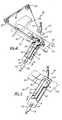
- FIG. 4 to 6 Apparatus according to the invention for performing the method is shown diagrammatically in Figs. 4 to 6.
- the apparatus 20 can be an adaptation of the equipments fully disclosed in the Detexomat, patents noted hereinbefore and incorporated in this specification by reference. In view of the prior patents, and for simplicity, we do not describe such items as devices for loading and unloading the apparatus or devices for correctly positioning hose blanks thereon, although such devices may beneficially be incorporated in the apparatus 20.
- the apparatus 20 comprises a carrier 21 for supporting a hose blank H with at least the toe portion in a laid-flat condition.
- the carrier 21 comprises a pair of coplanar spaced-apart flat blades 22, 24 or the like. When a blank is placed on the blades, its fabric is stretched laterally and laid flat.
- the blades 22, 24 can, if desired, be laterally movable for stretching the blank H, in a manner akin to a glove stretcher.
- the carrier 21 includes a suction tube 25 for everting the blank H in the course of mounting it on the apparatus and, if desired, in the course of unloading it therefrom after toe closing.
- the apparatus 20 can include a plurality of movable carriers 21, e.g. mounted on a rotatable turret for movement in turn past the seamer.
- the hose blank toe end Prior to seaming, the hose blank toe end is presented to a clamping mechanism.
- the clamping, mechanism serves to grip the hose toe end portion along a predetermined seaming line and to convey it past the sewing head 27 of a sewing machine 28.
- the blades 22, 24 are movable to and fro to serve as means to present the toe end to the clamping mechanism.
- the blades are in a withdrawn position for receiving a hose blank H and are advanced forwardly for presenting its toe end into the clamping mechanism.
- the clamping mechanism can take various forms.
- the illustrated clamping mechanism comprises an endless flexible belt 30 trained around a plurality of pulleys or other guides 32, and a coacting support 34 beneath the belt.
- the support 34 extends to and past the seaming head 27 and includes an upstream support portion 35 and a downstream portion 36.
- the upstream portion 35 is hinged about an axis 38.
- portion 35 can move from a lowered position for the clamp to receive the toe end of blank H, to a raised position which is coplanar with the downstream support portion 36.
- the clamp is open or closed, depending on whether support portion 35 is lowered or raised level with portion 36.
- the belt 30 is movable, by drive means not, shown, to convey a clamped toe end to and past the seamer 28.
- Means 40 are provided for taking a hold of the hose toe end portion, effectively to immobilise the layer 11 preparatory to establishing the aforesaid displacement.
- the holding means 40 can be realised in various forms and is illustrated here by a ram 41 which actuates a holding element 42.
- the holding means 40 is located at or adjacent the hose-receiving part of the clamping mechanism.
- the holding element can then conveniently coact with the support 35 frictionally to grip layer 11,
- element 42 can incorporate impaling pins for entering the toe end at locations X, Fig. 2(a), to immobilise it enabling layer 12 to be displaced relative to layer 11.
- Displacing means 45 can also be realised in various forms and in the present example is generally similar to holding means 40.
- displacing means 45 comprises a fabric-gripping element 46 and an actuating ram 48 therefor.
- Element 46 can grip the fabric frictionally or mechanically by way of impaling pins, hooks or the like.
- element 46 embodies a pad comprising an elastomeric foam material which can frictionally engage the hose H between itself and a part of the carrier, such as the suction tube 25.
- the displacing means 45 is mounted or arranged in such a manner that element 46 can be moved into or out of a hose engaging position.
- the ram 48 When the ram 48 is activated, the element 46 is shifted in a longitudinal direction A relative to the carrier 21 to exert a pull on layer 12 engaged thereby.
- the ram stroke is arranged to displace layer 12 relative to layer 11 in a predetermined distance as described hereinbefore.
- the holding means 40 and displacing means 45 serve to establish the required mutual displacement between the layers 11, 12 prior to the clamp mechanism seizing the hose toe end. Thereafter, the said means 40, 45 disengage from the hose and the belt 30 of the clamp mechanism proceeds to advance the toe end to the seamer 28 while maintaining the mutual displacement.
- Operation of the apparatus 20 is as follows. Initially, the blades 22, 24 are in a withdrawn position with their free ends spaced from the clamp mechanism, The upstream portion 35 of support 34 is lowered so the clamp mechanism is open, and the holding and, displacing means 40, 45 are in inoperative states, i.e. with elements 42, 46 raised away from their operative positions. In this condition of the apparatus, the operator loads a tubular hose blank H on the carrier 21. The operator may position the toe end appropriately, for which purpose, the carrier 21 can include alignment markings, not shown. Alternatively, the task of positioning the toe end can be accomplished automatically by known positioning means.
- the operator hits a start button or pedal, or the apparatus commences operation after a timed delay designed to permit the operator to load the hose blank H.
- the blades 22, 24 of the carrier advance as a unit to position themselves and the toe end of the blank into the open clamp mechanism. The latter then commences to close, but no, actual clamping of the hose toe end occurs yet.
- the apparatus is then in the condition represented in Fig. 4.
- Fig. 5 shows the displacing means in the course of its fabric-displacing operation.
- the belt of the clamp mechanism is caused to move so as to convey the clamped toe end along the support 34 towards and past the seaming head 27.
- the grip exerted by the belt on the hose toe end preserves the_relative displacement between the, layers 11, 12.
- the seam line along which the seam is sewn is determined by the shape of the belt 30 at the hose receiving portion of the clamp mechanism.
- the guides or pulleys 32 here may shape the belt to a curve, which is reproduced as a correspondingly curved seam line as the blank passes the seaming head 27.
- the seam line may be linear instead, in which case the portion of belt 30 which seizes the toe end on closure of the clamp mechanism will be straight.
- Our aforesaid patents GB-B-1,501,869 and GB-B-1,577,758 should be read for further details of the construction and operation of the clamp mechanism.
- the hose can be manually or automatically discharged from the apparatus 20, and if desired everted in the process.
- the blades 22, 24, the clamp mechanism, the holding and displacing mechanism 40,45 and the belt drive all function in timed relationship to one another.
- the sequencing can be governed by mechanical operators such as cams, as is well known in the toe closing art.
- the displacing means 45 need not coact with the suction tube for gripping the hose, and it need not be positioned as shown to operate on the centreline of the carrier 21. If it operated offset from the centreline, the seam would be asymmetrical and this may be quite appropriate in some circumstances.
- An alternative displacing means comprises a movable plunger 50 disposed to be extended into the open end of the suction tube 25.
- a movable plunger 50 With the hose toe portion supported by the blades 22, 24 one, e.g. the upper layer 12 of the fabric is suitably immobilised by the holding means 40.
- the plunger is then activated to move a predetermined distance into the tube 25.
- the plunger 50 thrusts a portion of the other layer 11 of fabric rearwardly into the tube 25.
- the action of the plunger displaces the said other, e.g. the lower, fabric layer and establishes the required pre-seaming condition of the toe end.
- Toe closers which dispense with clamping mechanisms and means to present a hose toe end thereto.
- a hose blank is mounted on a carrier which is arranged to execute, a movement past the seamer.
- the latter generates a toe closing seam across the passing blank, in a portion thereof which protrudes just beyond a free end of the carrier.
- the carrier comprises a pair of blades which maintain the toe portion of the blank in a laid-flat condition suitable for seaming.
- Such a toe closing arrangement could be used for practising the present invention, when means will be required to establish the mutual displacement between the fabric layers and maintain it during seaming.
- the said means could be realised by a first means to immobilise a part of the toe end and a second means which engages, pulls and stretches one of the layers forwardly with respect to the other.
- Said first and second means would be movable with the carrier and, having established a predetermined displacement, would retain it until the seam has been generated.
- the first and second means can comprise suitable fabric gripping devices and the second means is operable, for instance by a ram, through a predetermined forward pulling stroke extending generally longitudinally relative to the carrier.
- Fig. 8(a)-(c) illustrates the principles of operation of such a toe closer.
- the hose blank H is mounted on the blades 22, 24 of the moving carrier 21 and the first and second means are indicated at 40, 45.
- the carrier moves in the direction of arrow A.
- the blades 22, 24 have opened to spread the toe end of the blank H into a laid-flat condition.
- the first means 40 has moved into contact with one layer 11 of the blank while the second means 45 has suitably gripped layer 12 and pulled this layer forwardly, displacing it relative to the substantially immobilised layer 11.
- the carrier is moving the hose toe end past the sewing head 27 of the seamer, generating the seam S along the seam line SL.
- the first and second means 40, 45 remain in their respective positions of Fig. 8(b) during the seaming operation.
- toe closers having a carrier and a clamping mechanism, in which the carrier itself, does not advance the toe end of a hose blank into the clamping mechanism.
- a separate reciprocally operable clamp-loading device is incorporated in such a toe closer.
- the loading device reciprocates from the hose carrier, from which it fakes hold of the hose toe end, and into the clamping mechanism.
- the device functions to stretch the toe end laterally, into a laid-flat condition, before the fabric is gripped by the clamping mechanism. It will be recognised that such a toe closer could embody means according to this invention at the clamping mechanism for effecting the required displacement between the confronting fabric layers prior to the clamping mechanism gripping the fabric.
Abstract
Description
- The present invention relates to a hosiery toe closing method and apparatus.
- More particularly, but not exclusively, the invention concerns the toe closing of socks. Stockings or pantihose could be toe closed by means of this invention.
- As is well known, hosiery is knitted in a tubular form. One end of each tube blank has to be closed in some way, to form the toe end. Two toe closing techniques are in general use. These techniques are diagrammatically illustrated in the accompanying Fig. 1(a) to (d) to which reference is now directed.
- One technique involves reciprocating the knitting machine during the knitting operation to form what is known as a reciprocated toe or pouch P, see Fig. 1a, b. When the knitting operation is complete, there is a gap G between the end edge of the pouch P and the adjacent portion of the knit. The confronting knit edges form the "looper line" and have to be seamed together to finish the hose toe. Having produced the sock with a reciprocated toe, the closure is usually effected by automatic looper line closing machines or by a simple overlock sewing machine, to form the seam S. This technique is sometimes referred to as "looper line" toe closing.
- The second technique is to knit a straight tubular hose blank toe and to close it by hand seaming or by automatic machines such as the Detexomat (RTM) Speedomatic (RTM) half hose toe closer. Using such a machine, the hose blank is disposed in a laid-flat condition, clamped along the intended seam line S (see Fig. Ic, d) and then moved past the seamer, e.g. an overlock machine, to form the curved seam S. Beyond the seam S the knitted material T is waste and is trimmed off during or after seaming.
- Neither technique is ideal, however. The looper line approach can produce good seams comfortable to the wearer, but closing along the looper line is relatively slow, even when costly looper line closing machines are employed. Care must be taken to load the hose properly into the looper line machine.
- The alternative technique is well established, especially in the manufacture of conventional ladies stockings and pantihose. Excellent production rates are attained. The technique is not entirely suited to sock production, however. Apart from the waste factor, there is a drawback in that the seam may not be as comfortable as desired. The seam S, which is somewhat bulky, lies across the ends of the wearer's toes where it may cause some discomfort. For preference, the seam should be above the wearer's toes or beneath them, in the hollow between the toes and the ball of the foot. The standard toe closing technique cannot readily emulate the looper line technique in so locating the seam.
- The present invention aims to achieve production rates approaching those of the conventional toe closing technique while obtaining seams or joins akin in location to those produced by the looper line technique.
- By appropriately manipulating the tubular hose blank before seaming, the seam or join can be caused to adopt an over-foot or under-foot position simply and of its own accord. Actual seaming or joining can be carried out along a straight line path or along a chosen curve if a deeper or shallower toe end were required, for instance.
- According to the present invention, there is provided a method for closing the toe of a tubular hose blank comprising the steps of:
- a) placing said blank in a flattened condition defining juxtaposed layers at an open end of same;
- b) longitudinally displacing one of said layers with respect to said other layer; and
- c) joining said layers along a predetermined line across said blank while maintaining the relative displacement between said layers.
- Also according to the invention, there is provided apparatus for closing the toe of a tubular hose blank, comprising means for arranging a toe end of the blank in a flattened condition defining two juxtaposed layers and means for joining the layers along a predetermined line across the blank, characterised by means for displacing at least one of the layers longitudinally of the blank to establish a relative mutual displacement between the layers, and by the apparatus being arranged to maintain the said displacement while the layers are joined by the joining means.
- The action of establishing the mutual displacement appears to produce a complex tensioning of the fabric and in effect creates a surplusage of fabric in one of the layers. When the join is completed and the hose is released, the surplusage will redistribute itself in the hose thanks to a relaxation of the fabric. In consequence of the redistribution, the join becomes positioned somewhat away from the actual toe end of the hose. If the laid-flat blank were appropriately oriented at the outset, with the intended top and bottom portions of the finished hose being constituted by the said two layers, then the join can ultimately adopt an over-foot or under-foot configuration. The resulting hose will closely resemble a hose closed by the much slower looper line technique.
- A movable clamping means can be employed to convey the hose past means for joining the layers, thereby to generate the toe-closing join, so long as the mutual displacement of the layers is preserved during the movement. Suitable clamping means are known and are disclosed in our patents GB-B-1,039,104; GB-B-1,501,869; GB-B-1,577,758 and GB-B-2,074,203. By appropriate movement of the clamping means, the join can be formed along a line of predetermined shape which may be linear or curved.
- Apparatus featuring such clamping means can further comprise a hose blank carrier and loading means for the clamping means, the loading means being operable to take hold of the toe end of the blank on the carrier, to convey the toe end to the clamping means and to arrange the toe end in the flattened condition by stretching it laterally, and at the clamping means are the displacing means which are- operable to establish the said displacement before the clamping means clamp the two juxtaposed and mutually displaced layers.
- The toe-closing join will preferably be made by sewing, e.g. overlock sewing. Other joining methods could be adopted in appropriate cases, e.g. ultrasonic welding.
- In performing the present invention, it is preferred to displace one layer positively relative to the other while the latter is effectively restrained in some way from being displaced. The said one layer can be pushed longitudinally away from the end edge of the said other layer.
- One apparatus according to the present invention comprises:
- a) hose carrier means for mounting said blank in a flattened condition with juxtaposed layers at an outer, open end of same;
- b) means for relatively displacing at least one of said layers with respect to the other layer to establish the predetermined mutual displacement between said layers;
- c) clamping means for receiving a toe end of said blank supported on said mounting means; and
- d) means for joining said layers along a predetermined line across said blank; said clamping means being operative (i) to grip said toe end after establishment of said displacement, (ii) to convey said toe end past the joining means for the latter to join the layers along said line and (iii) to preserve said displacement while conveying said toe end past the joining means.
- Blanks to be toe closed by the apparatus need no reciprocated toe or pouch and hence the knitting thereof is simplified. The apparatus can conveniently comprise an adaptation of known types of toe closer.
- The preferred hose carrier or mounting means comprises a pair of spaced-apart, flat blades or fingers. They may be movable apart to stretch the hose toe end laterally to establish the laid-flat condition. The blades can be associated with a suction tube for everting the hose blank.
- In preferred apparatus according to the invention, a holding means serves to immobilise a part or parts of the blank toe end while the displacing means acts on one of said layers and thereby establishes the said mutual displacement. Once the clamp mechanism of the toe closer has gripped the hose, the holding means may thereafter disengage from the toe end. The displacement means can comprise a reciprocally-movable element engageable with the said second layer, said element being disengageable therefrom after executing a displacing stroke when the clamp has gripped the toe end.
- The preferred clamping means comprises an endless flexible belt and a cooperating support between which the hose toe end is gripped, the belt being movable to advance the toe end across the support past the seamer. Conveniently, at a toe end receiving part of the clamp, the clamp comprises belt-shaping means which enable the belt to grip the toe end along a predetermined linear or curvilinear line corresponding to the configuration of a predetermined seam line.
- If desired, the clamp could be omitted, where the toe closer has the mounting means supported to move past the joining means appropriately for the latter to join the layers of the passing toe end. The means to displace the layers relative to one another will move in step with the mounting means to maintain the mutual displacement while joining proceeds.
- Accordingly, the present invention also provides apparatus for closing the toe of a tubular hose blank comprising a hose blank carrier which serves to arrange the toe end of a hose blank carried thereby in a flattened condition, the carrier being movable to convey the two juxtaposed layers past the joining means for the latter to join them along the said line, and the displacing means are movable with the carrier and, after establishing the said displacement, the displacing means continue to maintain the displacement until after the two layers are joined.
- The invention will now be explained in more detail with reference to the accompanying drawings, in which:
- Figs. 1(a) and 1(b) are side and top views illustrative of the known looper line toe closing technique, and Figs. I(c) and I(d) are "before and after", top views illustrative of toe closing using tubular blanks;
- Figs. 2(a) to 2(e) diagrammatically illustrate toe closing according to this invention,
- Figs. 3(a) to 3(c) diagrammatically illustrate the condition of the knitted fabric during toe closing according to this invention,
- Fig. 4 illustrates in simplified form a perspective view of apparatus according to the invention,
- Figs. 5 and 6 illustrate in further simplified form certain stages in the operation of the apparatus,
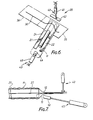
- Fig. 7 diagrammatically illustrates another embodiment of the invention, and
- Figs. 8(a) to 8(c) schematically illustrate the Principles of operation of another apparatus embodying the invention.
- The two conventional toe closing techniques have already been discussed in connection with Figs. 1(a) to (d). By this invention, we are seeking to produce a closed hose toe which resembles a reciprocated toe in having an over or under foot seam, yet is susceptible of production from the simpler tubular type of hose blank. The method according to this invention can be implemented by an adaptation of a known toe closer type such as is disclosed in the aforementioned patent specificati ons e.g. GB-B-1,577,758. Such toe closers can achieve extremely high production rates, much higher than present looper line toe closers.
- Figs. 2(a) to (e) conveniently show the steps of our preferred method. A tubular hose blank H, or at least the
toe end portion 10 thereof, is first placed in a laid-flat condition. This condition is most readily attained by laterally stretching the blank H, for example by placing it on a suitably dimensioned flat form, not shown. In the laid-flat condition, first andsecond layers - In the second step of the method, part of the toe end, e.g. the
free end 14 oflayer 11, is restrained from moving andlayer 12 is pulled or pushed longitudinally in the direction A away from theend 14 oflayer 11. The corresponding free end oflayer 12 is drawn backwardly fromend 14 and assumes a curved form as shown. Thanks to this second step of the method, aneffective surplusage 15 of loose hose fabric is created or accumulated inlayer 12. Moreover, the distortion of the fabric sets up a complex state of tension in the twolayers layers much surplusage 15 is accumulated. - Having established a predetermined mutual displacement between
layers - The fourth step of the method accomplishes seaming along line SL by conveying the hose toe end past a seamer, with its
layers - After seaming and while the toe end is still in the laid-flat condition, the hose toe can be visualised in side elevation as shown in Fig. 2(c). The seam S extends transversely of the blank H and is at the extreme end thereof. The
loose surplusage 15 is still located inlayer 12 rearwardly of the seam S. Upon releasing the hose from the laid-flat condition, its fabric will relax of its own accord and commence to redistribute itself. Thesurplusage 15 will move towards the hose toe end portion and the seam S will move towards an under- or over-foot position, see Fig. 2(d). Fig. 2(e) illustrates the resulting toe closed hose as seen from the side. Thetoe portion 16 is formed by thesurplusage 15. - It will be recognised that when
layer 12 is placed atoplayer 11 as shown in Figs. 2(a) to (e), an underfoot seam results if the intended top of the hose H is constituted bylayer 12. Should the intended bottom of the hose be constituted bylayer 12, an overfoot seam results so long aslayer 12 is atoplayer 11. - The actual seam S will be arcuate even though it may be sewn along a straight seam line SL. As the tubular blank H is knitted, its rows or courses of stitches run helically. When the blank is in the laid-flat condition, these courses extend transversely, to all intents and purposes. See Fig. 3(a), the courses being indicated by
reference 18. Upon displacing onelayer 12 relative to theother layer 11, thecourses 18 inlayer 12 become arcuately distorted, see Fig. 3(b), when thesurplusage 15 is created. If the seam S is generated along a straight seam line and the laid-flat condition is thereafter removed, the courses will straighten towards their original configuration and the seam will take on a curved form. - The seam line SL can be arcuate, in which case the ultimate seam S can have a more or less pronounced curve and the
toe portion 16 can thus be made deeper or shallower. A variety of toe forms can be obtained by varying (i) the shape of the seam line SL and (ii) the magnitude of the mutual displacement between thelayers - Apparatus according to the invention for performing the method is shown diagrammatically in Figs. 4 to 6. The
apparatus 20 can be an adaptation of the equipments fully disclosed in the Detexomat, patents noted hereinbefore and incorporated in this specification by reference. In view of the prior patents, and for simplicity, we do not describe such items as devices for loading and unloading the apparatus or devices for correctly positioning hose blanks thereon, although such devices may beneficially be incorporated in theapparatus 20. - The
apparatus 20 comprises acarrier 21 for supporting a hose blank H with at least the toe portion in a laid-flat condition. Thecarrier 21 comprises a pair of coplanar spaced-apartflat blades blades carrier 21 includes asuction tube 25 for everting the blank H in the course of mounting it on the apparatus and, if desired, in the course of unloading it therefrom after toe closing. - The
apparatus 20 can include a plurality ofmovable carriers 21, e.g. mounted on a rotatable turret for movement in turn past the seamer. - Prior to seaming, the hose blank toe end is presented to a clamping mechanism. The clamping, mechanism serves to grip the hose toe end portion along a predetermined seaming line and to convey it past the
sewing head 27 of asewing machine 28. Most expeditiously, theblades - As is known in the art, the clamping mechanism can take various forms. By way of example, the illustrated clamping mechanism comprises an endless
flexible belt 30 trained around a plurality of pulleys orother guides 32, and acoacting support 34 beneath the belt. Thesupport 34 extends to and past the seaminghead 27 and includes anupstream support portion 35 and adownstream portion 36. Theupstream portion 35 is hinged about anaxis 38.portion 35 can move from a lowered position for the clamp to receive the toe end of blank H, to a raised position which is coplanar with thedownstream support portion 36. The clamp is open or closed, depending on whethersupport portion 35 is lowered or raised level withportion 36. When the clamp has been closed, thebelt 30 is movable, by drive means not, shown, to convey a clamped toe end to and past theseamer 28. - Means 40 are provided for taking a hold of the hose toe end portion, effectively to immobilise the
layer 11 preparatory to establishing the aforesaid displacement. The holding means 40 can be realised in various forms and is illustrated here by aram 41 which actuates a holdingelement 42. In this embodiment, the holding means 40 is located at or adjacent the hose-receiving part of the clamping mechanism. The holding element can then conveniently coact with thesupport 35 frictionally to griplayer 11, Alternatively,element 42 can incorporate impaling pins for entering the toe end at locations X, Fig. 2(a), to immobilise it enablinglayer 12 to be displaced relative tolayer 11. - Allied with holding means 40 is means 45 for displacing
layer 12 longitudinally relative to layer 11. Displacing means 45 can also be realised in various forms and in the present example is generally similar to holdingmeans 40. Thus, displacing means 45 comprises a fabric-grippingelement 46 and anactuating ram 48 therefor.Element 46 can grip the fabric frictionally or mechanically by way of impaling pins, hooks or the like. As shown,element 46 embodies a pad comprising an elastomeric foam material which can frictionally engage the hose H between itself and a part of the carrier, such as thesuction tube 25. The displacing means 45 is mounted or arranged in such a manner thatelement 46 can be moved into or out of a hose engaging position. When theram 48 is activated, theelement 46 is shifted in a longitudinal direction A relative to thecarrier 21 to exert a pull onlayer 12 engaged thereby. The ram stroke is arranged to displacelayer 12 relative to layer 11 in a predetermined distance as described hereinbefore. - The holding means 40 and displacing means 45 serve to establish the required mutual displacement between the
layers belt 30 of the clamp mechanism proceeds to advance the toe end to theseamer 28 while maintaining the mutual displacement. - Operation of the
apparatus 20 is as follows. Initially, theblades upstream portion 35 ofsupport 34 is lowered so the clamp mechanism is open, and the holding and, displacing means 40, 45 are in inoperative states, i.e. withelements carrier 21. The operator may position the toe end appropriately, for which purpose, thecarrier 21 can include alignment markings, not shown. Alternatively, the task of positioning the toe end can be accomplished automatically by known positioning means. Having loaded the hose, the operator hits a start button or pedal, or the apparatus commences operation after a timed delay designed to permit the operator to load the hose blank H. During the operation of the apparatus, theblades - Next, the holding means 40 and displacing means 45 are activated, The holding
element 42 is engaged with the toe end, effectively immobilisinglayer 11 thereof, (as shown in Fig. 5) and the displacing means 45 is activated to engage its, displacingelement 46 with thelayer 12 of the hose blank H and to shiftelement 46 in direction A. Fig. 5 shows the displacing means in the course of its fabric-displacing operation. - When
layer 12 has been displaced relative to layer 11 a predetermined distance, ram 48 stops butelements layers support portion 35 being lifted level withsupport portion 36. Once closed, the clamp mechanism holds thelayers means blades seamer 30. At this time, the apparatus is in the condition illustrated in Fig. 6. - For generating the seam, the belt of the clamp mechanism is caused to move so as to convey the clamped toe end along the
support 34 towards and past the seaminghead 27. During this movement, the grip exerted by the belt on the hose toe end preserves the_relative displacement between the, layers 11, 12. The seam line along which the seam is sewn is determined by the shape of thebelt 30 at the hose receiving portion of the clamp mechanism. As shown, the guides orpulleys 32 here may shape the belt to a curve, which is reproduced as a correspondingly curved seam line as the blank passes the seaminghead 27. As aforesaid, the seam line may be linear instead, in which case the portion ofbelt 30 which seizes the toe end on closure of the clamp mechanism will be straight. Our aforesaid patents GB-B-1,501,869 and GB-B-1,577,758 should be read for further details of the construction and operation of the clamp mechanism. - After seaming and trimming has been performed, the hose can be manually or automatically discharged from the
apparatus 20, and if desired everted in the process. For further details, see our aforementioned patent specifications. - When the seamed blank is released from the clamp mechanism and is freed from the laterally stretched laid-flat condition, the fabric will readjust itself and the layers (11, 12) will resume their normal relaxed relative dispositions. The
surplusage 15 will therefore so disperse itself that it will form the hose toe and the seam S will move into an overfoot or underfoot position. - The
blades mechanism - The invention can be practised in ways other than described above. For example, the displacing means 45 need not coact with the suction tube for gripping the hose, and it need not be positioned as shown to operate on the centreline of the
carrier 21. If it operated offset from the centreline, the seam would be asymmetrical and this may be quite appropriate in some circumstances. - An alternative displacing means, see Fig. 7, comprises a
movable plunger 50 disposed to be extended into the open end of thesuction tube 25. With the hose toe portion supported by theblades upper layer 12 of the fabric is suitably immobilised by the holding means 40. The plunger is then activated to move a predetermined distance into thetube 25. As it moves, theplunger 50 thrusts a portion of theother layer 11 of fabric rearwardly into thetube 25. The action of the plunger displaces the said other, e.g. the lower, fabric layer and establishes the required pre-seaming condition of the toe end. - As illustrated and described, with reference to Figs. 2 to 6, the mutual displacement of
layers fabric surplusage 15 inlayer 12. By a straightforward relocation of themeans layer 11 whilelayer 12 is held immobile. - Another possible modification to the technique establishes the required mutual displacement by stretching one layer longitudinally relative to the other, which is suitably immobilised.
- The required mutual displacement could be attained by a combination of the techniques outlined above. Thus, one layer could be stretched longitudinally while the other layer is displaced, longitudinally in the opposite direction so as to accumulate a fabric surplusage in the latter. In effect, fabric displacing forces are exerted on the two layers in opposite longitudinal directions.
- Toe closers are known which dispense with clamping mechanisms and means to present a hose toe end thereto. In such a toe closer, a hose blank is mounted on a carrier which is arranged to execute, a movement past the seamer. The latter generates a toe closing seam across the passing blank, in a portion thereof which protrudes just beyond a free end of the carrier. The carrier comprises a pair of blades which maintain the toe portion of the blank in a laid-flat condition suitable for seaming. Such a toe closing arrangement could be used for practising the present invention, when means will be required to establish the mutual displacement between the fabric layers and maintain it during seaming. The said means could be realised by a first means to immobilise a part of the toe end and a second means which engages, pulls and stretches one of the layers forwardly with respect to the other. Said first and second means would be movable with the carrier and, having established a predetermined displacement, would retain it until the seam has been generated. The first and second means can comprise suitable fabric gripping devices and the second means is operable, for instance by a ram, through a predetermined forward pulling stroke extending generally longitudinally relative to the carrier.
- Fig. 8(a)-(c) illustrates the principles of operation of such a toe closer. In Fig. 8(a), the hose blank H is mounted on the
blades carrier 21 and the first and second means are indicated at 40, 45. The carrier moves in the direction of arrow A. In Fig. 8(b), theblades layer 11 of the blank while the second means 45 has suitably grippedlayer 12 and pulled this layer forwardly, displacing it relative to the substantially immobilisedlayer 11. In Fig.-8(c), the carrier is moving the hose toe end past thesewing head 27 of the seamer, generating the seam S along the seam line SL. The first and second means 40, 45 remain in their respective positions of Fig. 8(b) during the seaming operation. - Also known are toe closers having a carrier and a clamping mechanism, in which the carrier itself, does not advance the toe end of a hose blank into the clamping mechanism. A separate reciprocally operable clamp-loading device is incorporated in such a toe closer. The loading device reciprocates from the hose carrier, from which it fakes hold of the hose toe end, and into the clamping mechanism. The device functions to stretch the toe end laterally, into a laid-flat condition, before the fabric is gripped by the clamping mechanism. It will be recognised that such a toe closer could embody means according to this invention at the clamping mechanism for effecting the required displacement between the confronting fabric layers prior to the clamping mechanism gripping the fabric.
- By varying the magnitude of the mutual displacement and/or by varying the configuration of the seam line (by adjusting the belt shape at the hose-receiving portion of the clamp mechanism), considerable control over the toe depth and shape and the seam position in the finished sock can be readily realised.
- Those skilled in the art will recognise, or be able to ascertain using no more than routine experimentation. equivalents to the specific procedures and mechanical arrangements described herein.
Claims (25)
Priority Applications (1)
| Application Number | Priority Date | Filing Date | Title |
|---|---|---|---|
| AT85306007T ATE39371T1 (en) | 1984-09-05 | 1985-08-23 | METHOD AND DEVICE FOR CLOSING THE END OF STOCKINGS. |
Applications Claiming Priority (2)
| Application Number | Priority Date | Filing Date | Title |
|---|---|---|---|
| GB848422370A GB8422370D0 (en) | 1984-09-05 | 1984-09-05 | Hosiery toe |
| GB8422370 | 1984-09-05 |
Publications (2)
| Publication Number | Publication Date |
|---|---|
| EP0177159A1 EP0177159A1 (en) | 1986-04-09 |
| EP0177159B1 true EP0177159B1 (en) | 1988-12-21 |
Family
ID=10566267
Family Applications (1)
| Application Number | Title | Priority Date | Filing Date |
|---|---|---|---|
| EP85306007A Expired EP0177159B1 (en) | 1984-09-05 | 1985-08-23 | Hosiery toe closing method and apparatus |
Country Status (5)
| Country | Link |
|---|---|
| US (1) | US4609419A (en) |
| EP (1) | EP0177159B1 (en) |
| AT (1) | ATE39371T1 (en) |
| DE (1) | DE3566913D1 (en) |
| GB (1) | GB8422370D0 (en) |
Families Citing this family (8)
| Publication number | Priority date | Publication date | Assignee | Title |
|---|---|---|---|---|
| GB8730199D0 (en) * | 1987-12-24 | 1988-02-03 | Detexomat Machinery Ltd | Hosiery toe closing method & apparatus |
| US6158367A (en) * | 1999-03-17 | 2000-12-12 | B. B. & S. Knitting Consultants | Apparatus and method for automatically orienting hosiery articles for closing toe ends thereof |
| US7025011B2 (en) * | 2003-01-24 | 2006-04-11 | B.B. & S Knitting Consultants | Apparatus for automatically orienting hosiery articles for closing toe ends thereof |
| US7044071B2 (en) * | 2003-01-24 | 2006-05-16 | B.B. & S Knitting Consultants | Apparatus and method for automatically orienting hosiery articles for closing toe ends thereof |
| US6779472B1 (en) | 2003-03-25 | 2004-08-24 | Sara Lee Corporation | Hosiery toe closing apparatus and method |
| ITMI20121604A1 (en) * | 2012-09-26 | 2014-03-27 | Boggiani Renato S R L | EQUIPMENT AND PROCEDURE FOR THE PRODUCTION OF TIGHTS |
| IT201600082235A1 (en) * | 2016-08-04 | 2018-02-04 | Golden Lady Co Spa | DEVICE AND METHOD TO SEW THE TIP OF A TUBULAR KNITTED MANUFACTURE |
| TWI749282B (en) * | 2018-01-18 | 2021-12-11 | 大康織機股份有限公司 | Sewing machine and method for closing open end of tubular knitted articles |
Family Cites Families (11)
| Publication number | Priority date | Publication date | Assignee | Title |
|---|---|---|---|---|
| US3090963A (en) * | 1957-07-26 | 1963-05-28 | West Orange Hosiery Mill Inc | Circular knit hosiery and method of closing the toe opening |
| US2980917A (en) * | 1959-06-22 | 1961-04-25 | Us Trust Company Of New York | Circular knit hosiery and method of closing the toe thereof |
| GB1501869A (en) * | 1974-06-03 | 1978-02-22 | Detexomat Machinery Ltd | Seaming |
| GB1542827A (en) * | 1976-10-26 | 1979-03-28 | Takatori Machinery Works Ltd | Automatic method and apparatus for closing a toe end of a hose utilizing a straight line stitch |
| US4102727A (en) * | 1977-03-21 | 1978-07-25 | Hanes Corporation | Method for closing end portions of tubular fabric articles |
| GB1577758A (en) * | 1977-04-02 | 1980-10-29 | Detexomat Machinery Ltd | Garment manufacture |
| JPS5566387A (en) * | 1978-11-11 | 1980-05-19 | Tatsuo Sakonishi | Nose crosssstitch method of sock by series system |
| US4383491A (en) * | 1980-01-07 | 1983-05-17 | Detexomat Machinery Limited | Method and apparatus for hosiery manufacture |
| GB2074203B (en) * | 1980-04-18 | 1983-06-29 | Detexomat Machinery Ltd | Hosiery toe closing machine |
| JPS59218188A (en) * | 1983-05-26 | 1984-12-08 | 株式会社タカトリ機械製作所 | Automatic position determining method and apparatus of hose end part |
| US4538534A (en) * | 1984-05-09 | 1985-09-03 | Kayser-Roth Hosiery, Inc. | Apparatus and method for processing hosiery blanks |
-
1984
- 1984-09-05 GB GB848422370A patent/GB8422370D0/en active Pending
-
1985
- 1985-08-19 US US06/766,566 patent/US4609419A/en not_active Expired - Lifetime
- 1985-08-23 DE DE8585306007T patent/DE3566913D1/en not_active Expired
- 1985-08-23 AT AT85306007T patent/ATE39371T1/en not_active IP Right Cessation
- 1985-08-23 EP EP85306007A patent/EP0177159B1/en not_active Expired
Also Published As
| Publication number | Publication date |
|---|---|
| ATE39371T1 (en) | 1989-01-15 |
| GB8422370D0 (en) | 1984-10-10 |
| DE3566913D1 (en) | 1989-01-26 |
| EP0177159A1 (en) | 1986-04-09 |
| US4609419A (en) | 1986-09-02 |
Similar Documents
| Publication | Publication Date | Title |
|---|---|---|
| US5437238A (en) | Waist band attachment system | |
| US4903621A (en) | Hosiery toe closing method and apparatus | |
| CZ20011295A3 (en) | Process and apparatus for sewing sock toe | |
| EP0177159B1 (en) | Hosiery toe closing method and apparatus | |
| US4188898A (en) | System for combining stocking materials and gussets to form panty hose garments | |
| CA1036432A (en) | Seaming machinery | |
| US4133276A (en) | Stocking toe end closing apparatus | |
| EP3194646B1 (en) | Method and apparatus for sewing an open end of a tubular textile item to make the toe of a sock or of a leg of a stocking | |
| JPH01259892A (en) | Automatic mounting device of raw material of panty hose | |
| US4538534A (en) | Apparatus and method for processing hosiery blanks | |
| EP1118700B1 (en) | Method and device for producing tubular knitted articles and for closing their toes | |
| JPH10513394A (en) | Locker / Patch mounting device | |
| CN209098911U (en) | It is a kind of forming hosiery machine sock piece-end sewing at transfer connect needle | |
| JPH05505547A (en) | Sewing machine equipped with automatic latchback device and its sewing method | |
| JPH05253373A (en) | Machine for automatically sewing toes of pantyhose | |
| US5555832A (en) | Apparatus for manufacturing hosiery items and knitting and stitching machines | |
| US5207166A (en) | Method and apparatus for making pantyhose with a comfort gusset | |
| JP2567087B2 (en) | Automatic stitching device | |
| US5979345A (en) | Spindle tension system for sewing station | |
| TWI772316B (en) | Device and method for sewing the toe of a tubular knitted article | |
| US5638998A (en) | Cuff inserting apparatus | |
| JPH0790952B2 (en) | Device for gripping and pulling the edge of a piece of cloth | |
| JPH0358756B2 (en) | ||
| AU583914B2 (en) | Handling limp fabric | |
| JP2001049505A (en) | Sewing panty stocking with back panel-like gore, and device for producing the same |
Legal Events
| Date | Code | Title | Description |
|---|---|---|---|
| PUAI | Public reference made under article 153(3) epc to a published international application that has entered the european phase |
Free format text: ORIGINAL CODE: 0009012 |
|
| AK | Designated contracting states |
Kind code of ref document: A1 Designated state(s): AT DE FR GB IT |
|
| 17P | Request for examination filed |
Effective date: 19860704 |
|
| 17Q | First examination report despatched |
Effective date: 19871120 |
|
| ITF | It: translation for a ep patent filed |
Owner name: BARZANO' E ZANARDO MILANO S.P.A. |
|
| GRAA | (expected) grant |
Free format text: ORIGINAL CODE: 0009210 |
|
| AK | Designated contracting states |
Kind code of ref document: B1 Designated state(s): AT DE FR GB IT |
|
| REF | Corresponds to: |
Ref document number: 39371 Country of ref document: AT Date of ref document: 19890115 Kind code of ref document: T |
|
| REF | Corresponds to: |
Ref document number: 3566913 Country of ref document: DE Date of ref document: 19890126 |
|
| ET | Fr: translation filed | ||
| PLBE | No opposition filed within time limit |
Free format text: ORIGINAL CODE: 0009261 |
|
| STAA | Information on the status of an ep patent application or granted ep patent |
Free format text: STATUS: NO OPPOSITION FILED WITHIN TIME LIMIT |
|
| 26N | No opposition filed | ||
| ITTA | It: last paid annual fee | ||
| PGFP | Annual fee paid to national office [announced via postgrant information from national office to epo] |
Ref country code: DE Payment date: 19940722 Year of fee payment: 10 |
|
| PGFP | Annual fee paid to national office [announced via postgrant information from national office to epo] |
Ref country code: AT Payment date: 19940830 Year of fee payment: 10 |
|
| PGFP | Annual fee paid to national office [announced via postgrant information from national office to epo] |
Ref country code: FR Payment date: 19950725 Year of fee payment: 11 |
|
| PGFP | Annual fee paid to national office [announced via postgrant information from national office to epo] |
Ref country code: GB Payment date: 19950817 Year of fee payment: 11 |
|
| PG25 | Lapsed in a contracting state [announced via postgrant information from national office to epo] |
Ref country code: AT Effective date: 19950823 |
|
| PG25 | Lapsed in a contracting state [announced via postgrant information from national office to epo] |
Ref country code: DE Effective date: 19960501 |
|
| PG25 | Lapsed in a contracting state [announced via postgrant information from national office to epo] |
Ref country code: GB Effective date: 19960823 |
|
| GBPC | Gb: european patent ceased through non-payment of renewal fee |
Effective date: 19960823 |
|
| PG25 | Lapsed in a contracting state [announced via postgrant information from national office to epo] |
Ref country code: FR Effective date: 19970430 |
|
| REG | Reference to a national code |
Ref country code: FR Ref legal event code: ST |