EP0176922A2 - Film mit senkrechter Magnetisierung und Herstellung desselben - Google Patents
Film mit senkrechter Magnetisierung und Herstellung desselben Download PDFInfo
- Publication number
- EP0176922A2 EP0176922A2 EP85112065A EP85112065A EP0176922A2 EP 0176922 A2 EP0176922 A2 EP 0176922A2 EP 85112065 A EP85112065 A EP 85112065A EP 85112065 A EP85112065 A EP 85112065A EP 0176922 A2 EP0176922 A2 EP 0176922A2
- Authority
- EP
- European Patent Office
- Prior art keywords
- substrate
- film
- chromium
- thin film
- magnetic thin
- Prior art date
- Legal status (The legal status is an assumption and is not a legal conclusion. Google has not performed a legal analysis and makes no representation as to the accuracy of the status listed.)
- Granted
Links
Images

Classifications
-
- G—PHYSICS
- G11—INFORMATION STORAGE
- G11B—INFORMATION STORAGE BASED ON RELATIVE MOVEMENT BETWEEN RECORD CARRIER AND TRANSDUCER
- G11B5/00—Recording by magnetisation or demagnetisation of a record carrier; Reproducing by magnetic means; Record carriers therefor
- G11B5/84—Processes or apparatus specially adapted for manufacturing record carriers
- G11B5/85—Coating a support with a magnetic layer by vapour deposition
-
- Y—GENERAL TAGGING OF NEW TECHNOLOGICAL DEVELOPMENTS; GENERAL TAGGING OF CROSS-SECTIONAL TECHNOLOGIES SPANNING OVER SEVERAL SECTIONS OF THE IPC; TECHNICAL SUBJECTS COVERED BY FORMER USPC CROSS-REFERENCE ART COLLECTIONS [XRACs] AND DIGESTS
- Y10—TECHNICAL SUBJECTS COVERED BY FORMER USPC
- Y10S—TECHNICAL SUBJECTS COVERED BY FORMER USPC CROSS-REFERENCE ART COLLECTIONS [XRACs] AND DIGESTS
- Y10S428/00—Stock material or miscellaneous articles
- Y10S428/90—Magnetic feature
-
- Y—GENERAL TAGGING OF NEW TECHNOLOGICAL DEVELOPMENTS; GENERAL TAGGING OF CROSS-SECTIONAL TECHNOLOGIES SPANNING OVER SEVERAL SECTIONS OF THE IPC; TECHNICAL SUBJECTS COVERED BY FORMER USPC CROSS-REFERENCE ART COLLECTIONS [XRACs] AND DIGESTS
- Y10—TECHNICAL SUBJECTS COVERED BY FORMER USPC
- Y10T—TECHNICAL SUBJECTS COVERED BY FORMER US CLASSIFICATION
- Y10T428/00—Stock material or miscellaneous articles
- Y10T428/31504—Composite [nonstructural laminate]
- Y10T428/31678—Of metal
Definitions
- the present invention relates to a perpendicular magnetization film used as a perpendicular magnetic storage medium which is suitable for high-density recording, and the preparation thereof.
- a magnetic storage medium used for such a purpose is prepared by the use of magnetic thin film which has an easy magnetization axis perpendicular to a plane of film.
- a magnetic storage of cobalt-chromium alloy prepared by means of sputtering or vacuum-evaporation method, and also a magnetic storage of barium-ferrite alloy prepared by means of coating or sputtering method.
- cobalt-chromium thin film For applying cobalt-chromium thin film to a perpendicular magnetic storage, a structure of single crystal or a structure close to single crystal must be provided.
- a substrate In a process of preparing an alloy having the above structure, a substrate needs to be heated to a temperature of more than 100°C or in some cases to a temperature of more than 200°C.
- a barium and ferrite powder consisting of uniform particles of about 0.1 ⁇ m in diameter must be provided. It costs much to produce such barium and ferrite powder.
- a substrate In a process of preparing a barium-ferrite film by means of sputtering method, a substrate needs to be heated to a temperature of about 500°C. Thus, a substrate of cheap plastic materials cannot be used.
- An object of the present invention is to solve the problem that an ordinary plastic material cannot be used for a substrate of a perpendicular magnetic storage of cobalt and chromium, and that a material of substrate is restricted within expensive polyimides, aluminum, glass, or the like because a substrate must be heated to a temperature of more than 100°C in a process of preparation thereof.
- Another object of the invention is to solve the problem that cobalt is rare and expensive resources.
- Still another object of the invention is to solve the problem that a perpendicular magnetic storage of barium-ferrite alloy has low saturation magnetization compared with cobalt-chromium alloy.
- a perpendicular magnetization film comprising a magnetic thin film of iron-chromium alloy, and also providing the preparation thereof.
- the film is supported on a substrate and has an easy magnetization axis perpendicular to a plane of substrate.
- the alloy contains chromium in an amount of 20 to 60 atomic %.
- the process for preparing the perpendicular magnetization film comprises depositing iron and chromium on the substrate under vacuum or atmosphere of argon gas at a low pressure.
- a magnetic thin film supported on a substrate is composed of chromium and iron wherein a content of chromium is 20 to 60 atomic %, preferably 30 to 50 atomic %, and a magnetic thin film possesses an easy magnetization axis perpendicular to a plane of substrate.
- a content of chromium is less than 20 % in the alloy, a crystal phase rich in iron is deposited on a substrate, and a film does not represent a perpendicular uniaxial anisotropy, and accordingly, a perpendicular anisotropy of a magnetic thin film is not present because of an existence of a strong demagnetizing field which is induced by a large saturation magnetization of the film.
- a thickness of a magnetic thin film is preferably 100 to 10,000 ⁇ , and most preferably 500 to 5000 ⁇ .
- the thickness of the film is below 100 A, a leakage flux is so small that a sensitivity for reading out the written informations is low.
- the thickness is more than 10,000 ⁇ , it will be difficult to write down the informations throughout a thickness of film.
- using a film of more than 10,000 A results in a waste of material and cost.
- the magnetic thin film of the invention is corrosion resistant because it contains much chromium.
- a magnetic film of iron-chromium alloy has present only a peak corresponding to a lattice constant at 2.07 to 2.08 ⁇ in a X-ray diffraction spectrum.
- Such a magnetic film having the above-mentioned peak represents a large perpendicular magnetic anisotropy.
- the crystal structure from which this diffraction peak originates is unknown.
- a perpendicular magnetic anisotropy of the film contrarily tends to be small.
- a magnetic thin film having a dominant peak corresponding to a range of 2.07 to 2.08 of lattice spacing is preferably used.
- a magnetic thin film When a magnetization in a direction perpendicular to a plane of substrate is more intense than a magnetization of any other direction of magnetization, a magnetic thin film is hereinafter referred to that the film has an easy magnetization axis perpendicular to a plane of substrate. That is to say, a residual magnetization determined from a magnetization- hysterisis curve along a direction perpendicular to a plane of substrate is large compared with residual magnetization in any other direction within a surface of substrate.
- Examples of substrates in the invention are a metal plate of aluminum or stainless steel, a sheet or film of polyesters, polyimides or polymethacrylates, and the like.
- a material of a substrate is not restricted within the above-mentioned, but the material must have a softening point of more than about 50°C and a thickness in a range of about 10 ⁇ m to about 10 mm.
- a perpendicular magnetization film of the invention can be deposited by means of evaporation method such as sputtering or vacuum-evaporation.
- a process for preparing a perpendicular magnetization film by means of sputtering is disclosed in the following description.
- necessary conditions to be suitably decided in a sputtering process include a composition of alloy or content of chromium, a temperature of substrate, a rate of deposition, and a pressure of atmospheric argon gas.
- a content of chromium in the alloy is 20 to 60 atomic %, and preferably 30 to 50 atomic %.
- a perpendicular magnetization film of the invention is obtained by setting up a temperature of substrate, rate of sputtering and pressure of argon gas.
- a structure of deposited film should be determined so that a diffraction peak corresponding to a lattice constant of 2.07 to 2.08 A becomes dominant in a X-ray diffraction spectrum.
- An upper limit of the range of a permitted temperature of substrate is decided according to a softening point of substrate.
- a temperature of substrate is low so as to obtain a crystal structure having a lattice constant of 2.07 to 2.08 A of a perpendicular magnetic film.
- a substrate should be cooled below room temperature with coolant such as water in a sputtering process.
- a temperature of substrate is selected in a range of about -50° to about 150°C, preferably 0° to 80°C, most preferably 0° to 50°C.
- a rate of sputtering is changed by adjusting a supplied power to a sputtering apparatus. When a power for sputtering is high, a deposition rate of magnetic film becomes high, and also a temperature of surface of substrate rises. Thus, a substrate should be cooled when a power of sputtering is large.
- a pressure of argon gas is usually set in a range of 1 x 10 to 1 x 10 -2 Torr.
- a mangetic thin film produced in the aforementioned conditions shows a crystal structure having a lattice constant of 2.07 to 2.08 R. The fact is judged from X-ray diffraction analysis.
- the surface of the obtained magnetic thin film might be equal to a 110-plane of a body-centered cubic structure of chromium- rich iron, but the above fact cannot be concluded at present.
- Examples of sputtering apparatuses used to prepare a magnetic thin film of the invention are DC (direct current)-sputtering apparatus, RF (radio frequency)-sputtering apparatus or ion-beam sputtering apparatus, and the like.
- a perpendicular mangetic anisotropy constant Ku is positive and more than 10 5 erg/cm 3
- a coercive force is more than 300 oersted (Oe)
- Another process for preparing a perpendicular magnetization film of the invention by means of vacuum-evaporation is disclosed in the following description.
- Examples of vacuum-evaporation processes which can be applied to the invention are resistive- heating-evaporation, electron-beam-heating-evaporation, and the like.
- conditions to be controlled in the process of vacuum-evaporation method essentially include a component of film and a temperature of substrate. Concentration of chromium in the alloy is 20 to 60 atomic % and preferably, 30 to 50 atomic % to obtain a perpendicular magnetization film.
- An evaporation can be performed either by evaporating iron and chromium, respectively, or by evaporating an alloy of iron and chromium including an amount of 20 to 50 atomic % of chromium. Evaporation of an alloy of iron an chromium can be suitably accomplished by reason that a vapor pressure of iron and a vapor pressure of chromium are not so different from each other.
- a temperature of substrate is unavoidably increased by a radiation of heat from an evaporator, and a substrate should be cooled to a temperature in a range of about 0° to about 100°C, preferably 0° to 80°C, and most preferably 0° to 50°C.
- the obtained magnetic film possesses a perpendicular magnetic anisotropy Ku of more than 10 5 erg/cm 3 . This value of Ku is nearly the same as in the case of sputtering-evaporation.
- a magnetic thin film prepared by the above- described processes has a large saturation magnetization, a large vertical magnetic anisotropy, and a large coersive force. Those magnetic properties are suitable as a perpendcular magnetic storge for recording high-density information.
- a suitably prepared example of magnetic thin film which is deposited by means of sputtering-evaporation method under the following conditions, i.e. concentration of chromium of 35 atomic %, deposition rate of 150 K/min, and pressure of argon gas of 1.5 x 10 -3 Torr, realizes a perpendicular magnetization film of iron-chromium alloy in a thickness of 4,000 R having a perpendicular magnetic anisotropy constant Ku of more than 5 x 10 5 erg/cm 3 , and coersive force Hc ⁇ of more than 500 Oe.
- Hc 1 is defined as a coersive force decided from a magnetization curve measured by applying a magnetic field perpendicular to a plane of substrate.
- the perpendicular magnetic thin film of iron-chromium alloy of the invention possesses a large perpendicular magnetic anisotropy and a large coercive force.
- Magnetic thin films of iron-chromium alloy were deposited on the glass-substrate of 1 mm in thickness by means of rf-magnetron sputtering apparatus.
- the target was an iron plate of a diameter of 3 inches and a thickness of 0.5 mm. Chromium chips of 10 mm square were put on the iron plate. The concentration of chromium in the film was controlled by changing the number of chromium chips.
- the distance between the substrate and the target was 5 cm.
- the pressure of argon gas was 1.5 x 10 -3 Torr.
- the temperature of the substrate was room temperature.
- the supplied power for sputtering was 50 W. Prior to the deposition, a sputtering was performed to clean the surface of target. After the above process was completed, the substrate was exposed to the target by opening the shutter. Thereafter the magnetic film was deposited on the substrate for 30 minutes.
- the thickness of the obtained magnetic thin film was measured by means of stylus step monitor.
- the composition of the film was measured by means of X-ray analyzer.
- the saturation magnetization Ms was measured by means of vibrating-sample-magnetometer.
- the apparent uniaxial magnetic anisotropy constant R 1 pependicular to the substrate was measured by a torque meter.
- Fig. 1 The results are shown in Table 1 and Fig. 1, wherein Ku changes in accordance with the variation of content of chromium in the film.
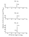
- the X-ray diffraction spectrum of the magnetic thin film obtained in the process of Example 2 is plotted in the graph of Fig. 2A.
- Fig. 3 is a graph illustrating a variance of intensity of diffracted X-rays versus a content of chromium where the diffraction angles 28 were 44.4° and 43.6°, respectively.
- the copper anode was used under an accelerating voltage of 30 kV and emission current of 50 m A.
- the power for sputtering was 50 W.
- Magnetic thin films containing a smaller amount of chromium were prepared under the same condition as in Example 1. Magnetic properties of the obtained magnetic thin films were measured. The results are shown in Table 1 and Fig. 1.
- the X-ray diffraction spectrum of the magnetic thin film prepared in the process of Comparative Example 1 is plotted in the graph of Fig. 2B.
- a variance of intensity of diffracted X-rays versus a content of chromium are plotted in the graph of Fig. 3, wherein the diffraction angles 26 were 44.4 0 and 43.6 0 , respectively. From the results of Table 1 and Fig. 1, it is seen that a perpendicular magnetization film cannot be obtained where a content of chromium is small. From the results of Fig.
- Magnetic thin films were prepared in the same condition as in Example 2 except that the temperatures of the substrate were different from the temperatures in Example 2.
- the magnetic properties of the obtained magnetic films were measured in the same manner as in Example 1. The results are shown in Table 1.
- the X-ray diffraction spectrum of the obtained magnetic thin film in Comparative Example 6 is plotted in the graph of Fig. 2C. From the results of Table 1 and the graph of Fig. 2C, it is seen that the oriented 110-plane of the body-centered cubic structure of Fe was deposited on the substrate at a high temperature, and the perpendicular magnetic anisotropy is vanishing.
- Magnetic thin films were prepared under the same condition as in Example 2 except that the supplied powers for sputtering or deposition rates were different from Examples 1 to 3.
- the measured magnetic properties of the obtained magnetic thin films are shown in Table 1.
- the powers for sputtering were 150 W in Example 4 and 300 W in Example 5, respectively.
- a magnetic thin film was deposited on the substrate under the same condition as in Example 2 except that the substrate was a film of polyethylene terephthalate of 76 ⁇ m thick, and the substrate was cooled to a temperature of 20°C and the supplied power for sputtering was 200 W.
- the concentration of chromium was 34.2 atomic %
- saturation magnetization was 250 emu/cm 3
- perpendicular magnetic anisotropy constant was 5.2 x 10 5 erg/cm and coersive force was 560 Oe.
- the curl of the plane of substrate was not actually recognized.
- X-ray diffraction analysis only a diffraction peak corresponding to a lattice constant of 2.074 A was recognized.
- a perpendicular magnetization film of iron-chromium alloy makes it possible to realize a corossive resistant and high-density magnetic storage at a low cost.
- a deposition of the film is carried out at a low temperature of substrate, thereby a cheap material of low heat-resistance can be used for a substrate.
Landscapes
- Thin Magnetic Films (AREA)
- Magnetic Record Carriers (AREA)
- Physical Vapour Deposition (AREA)
- Manufacturing Of Magnetic Record Carriers (AREA)
Applications Claiming Priority (2)
| Application Number | Priority Date | Filing Date | Title |
|---|---|---|---|
| JP59202196A JPS6179205A (ja) | 1984-09-27 | 1984-09-27 | 垂直磁化膜およびその製法 |
| JP202196/84 | 1984-09-27 |
Publications (3)
| Publication Number | Publication Date |
|---|---|
| EP0176922A2 true EP0176922A2 (de) | 1986-04-09 |
| EP0176922A3 EP0176922A3 (en) | 1987-02-04 |
| EP0176922B1 EP0176922B1 (de) | 1988-11-23 |
Family
ID=16453556
Family Applications (1)
| Application Number | Title | Priority Date | Filing Date |
|---|---|---|---|
| EP85112065A Expired EP0176922B1 (de) | 1984-09-27 | 1985-09-24 | Film mit senkrechter Magnetisierung und Herstellung desselben |
Country Status (4)
| Country | Link |
|---|---|
| US (1) | US4588647A (de) |
| EP (1) | EP0176922B1 (de) |
| JP (1) | JPS6179205A (de) |
| DE (1) | DE3566468D1 (de) |
Cited By (1)
| Publication number | Priority date | Publication date | Assignee | Title |
|---|---|---|---|---|
| FR2771756A1 (fr) * | 1997-12-03 | 1999-06-04 | Lorraine Laminage | Procede de depot sous vide d'un alliage a base de chrome-fer et utilisation pour traiter la surface de tole d'acier zingue |
Families Citing this family (2)
| Publication number | Priority date | Publication date | Assignee | Title |
|---|---|---|---|---|
| JPS62283422A (ja) * | 1986-05-14 | 1987-12-09 | Tohoku Metal Ind Ltd | 垂直磁気記録媒体の製造方法 |
| JPH0362312A (ja) * | 1989-07-28 | 1991-03-18 | Fuji Photo Film Co Ltd | 磁気記録媒体 |
Family Cites Families (4)
| Publication number | Priority date | Publication date | Assignee | Title |
|---|---|---|---|---|
| US4245008A (en) * | 1978-10-30 | 1981-01-13 | International Business Machines Corporation | Corrosion resistant magnetic recording media |
| EP0058894B1 (de) * | 1981-02-21 | 1986-04-16 | GfO Gesellschaft für Oberflächentechnik m.b.H. | Kratzfeste, antistatische Ton- und Bildträger und Verfahren zu ihrer Herstellung |
| JPS598143A (ja) * | 1982-07-07 | 1984-01-17 | Fuji Photo Film Co Ltd | 磁気記録媒体の製造法 |
| JPS5979426A (ja) * | 1982-10-29 | 1984-05-08 | Tdk Corp | 磁気記録媒体 |
-
1984
- 1984-09-27 JP JP59202196A patent/JPS6179205A/ja active Pending
-
1985
- 1985-09-24 DE DE8585112065T patent/DE3566468D1/de not_active Expired
- 1985-09-24 EP EP85112065A patent/EP0176922B1/de not_active Expired
- 1985-09-26 US US06/780,515 patent/US4588647A/en not_active Expired - Fee Related
Cited By (1)
| Publication number | Priority date | Publication date | Assignee | Title |
|---|---|---|---|---|
| FR2771756A1 (fr) * | 1997-12-03 | 1999-06-04 | Lorraine Laminage | Procede de depot sous vide d'un alliage a base de chrome-fer et utilisation pour traiter la surface de tole d'acier zingue |
Also Published As
| Publication number | Publication date |
|---|---|
| DE3566468D1 (en) | 1988-12-29 |
| EP0176922A3 (en) | 1987-02-04 |
| US4588647A (en) | 1986-05-13 |
| EP0176922B1 (de) | 1988-11-23 |
| JPS6179205A (ja) | 1986-04-22 |
Similar Documents
| Publication | Publication Date | Title |
|---|---|---|
| US4414287A (en) | Magnetic recording medium and its manufacture | |
| Van Dover et al. | Intrinsic anisotropy of Tb‐Fe films prepared by magnetron Co sputtering | |
| EP0265246B1 (de) | Magnetische Eisenoxydfilme und ihre Herstellung | |
| EP0210855A2 (de) | Magnetooptische Aufzeichnungsträger | |
| US5068022A (en) | Process for sputtering multilayers for magneto-optical recording | |
| CA1315612C (en) | Perpendicular magnetic storage medium | |
| Carey et al. | The magnetic and magneto‐optical properties of Co, Cr, Mn, and Ni substituted barium ferrite films | |
| US5106703A (en) | Platinum/cobalt multilayer film for magneto-optical recording | |
| US4663193A (en) | Process for manufacturing magnetic recording medium | |
| EP0176922B1 (de) | Film mit senkrechter Magnetisierung und Herstellung desselben | |
| US4710434A (en) | Optomagnetic recording medium | |
| US4645690A (en) | Method of manufacturing a magnetic media | |
| Tsoukatos et al. | Thickness effects on the magnetic hysteresis of Co-Pt films | |
| EP0164725B1 (de) | Film mit senkrechter Magnetisierung und dessen Herstellung | |
| US4588636A (en) | Magnetic recording medium | |
| EP0324854A1 (de) | Optomagnetisches speichermedium und verfahren zur herstellung | |
| EP0389297B1 (de) | Ein magnetischer Spin-Glas-Körper, ein magnetischer Aufnahmeträger und ein magnetisches Aufnahmegerät | |
| US5045412A (en) | Perpendicular magnetic storage medium | |
| US4764436A (en) | Iron-oxygen based perpendicular magnetized anisotropic thin film | |
| JPS60187954A (ja) | 磁性薄膜記録媒体 | |
| JP3520751B2 (ja) | 垂直磁気記録媒体及びその製造方法及びそれを使用した記憶装置 | |
| GB2176496A (en) | Magnetic head core | |
| JPS61292219A (ja) | 磁気記録媒体 | |
| JPS63124213A (ja) | 垂直磁気記録媒体 | |
| JPH0416849B2 (de) |
Legal Events
| Date | Code | Title | Description |
|---|---|---|---|
| PUAI | Public reference made under article 153(3) epc to a published international application that has entered the european phase |
Free format text: ORIGINAL CODE: 0009012 |
|
| AK | Designated contracting states |
Kind code of ref document: A2 Designated state(s): BE DE FR GB IT NL |
|
| PUAL | Search report despatched |
Free format text: ORIGINAL CODE: 0009013 |
|
| AK | Designated contracting states |
Kind code of ref document: A3 Designated state(s): BE DE FR GB IT NL |
|
| 17P | Request for examination filed |
Effective date: 19870317 |
|
| 17Q | First examination report despatched |
Effective date: 19870902 |
|
| GRAA | (expected) grant |
Free format text: ORIGINAL CODE: 0009210 |
|
| AK | Designated contracting states |
Kind code of ref document: B1 Designated state(s): BE DE FR GB IT NL |
|
| REF | Corresponds to: |
Ref document number: 3566468 Country of ref document: DE Date of ref document: 19881229 |
|
| ET | Fr: translation filed | ||
| ITF | It: translation for a ep patent filed | ||
| PLBE | No opposition filed within time limit |
Free format text: ORIGINAL CODE: 0009261 |
|
| STAA | Information on the status of an ep patent application or granted ep patent |
Free format text: STATUS: NO OPPOSITION FILED WITHIN TIME LIMIT |
|
| 26N | No opposition filed | ||
| ITTA | It: last paid annual fee | ||
| PGFP | Annual fee paid to national office [announced via postgrant information from national office to epo] |
Ref country code: NL Payment date: 19900930 Year of fee payment: 6 |
|
| PG25 | Lapsed in a contracting state [announced via postgrant information from national office to epo] |
Ref country code: NL Effective date: 19920401 |
|
| NLV4 | Nl: lapsed or anulled due to non-payment of the annual fee | ||
| PGFP | Annual fee paid to national office [announced via postgrant information from national office to epo] |
Ref country code: FR Payment date: 19920909 Year of fee payment: 8 |
|
| PGFP | Annual fee paid to national office [announced via postgrant information from national office to epo] |
Ref country code: GB Payment date: 19920911 Year of fee payment: 8 |
|
| PGFP | Annual fee paid to national office [announced via postgrant information from national office to epo] |
Ref country code: DE Payment date: 19921005 Year of fee payment: 8 |
|
| PGFP | Annual fee paid to national office [announced via postgrant information from national office to epo] |
Ref country code: BE Payment date: 19921028 Year of fee payment: 8 |
|
| PG25 | Lapsed in a contracting state [announced via postgrant information from national office to epo] |
Ref country code: GB Effective date: 19930924 |
|
| PG25 | Lapsed in a contracting state [announced via postgrant information from national office to epo] |
Ref country code: BE Effective date: 19930930 |
|
| BERE | Be: lapsed |
Owner name: KANEGAFUCHI KAGAKU KOGYO K.K. Effective date: 19930930 |
|
| GBPC | Gb: european patent ceased through non-payment of renewal fee |
Effective date: 19930924 |
|
| PG25 | Lapsed in a contracting state [announced via postgrant information from national office to epo] |
Ref country code: FR Free format text: LAPSE BECAUSE OF NON-PAYMENT OF DUE FEES Effective date: 19940531 |
|
| PG25 | Lapsed in a contracting state [announced via postgrant information from national office to epo] |
Ref country code: DE Effective date: 19940601 |
|
| REG | Reference to a national code |
Ref country code: FR Ref legal event code: ST |