EP0176433B1 - Procédé et dispositif de décarbonatation de minéraux par calcination en lit fluidisé - Google Patents
Procédé et dispositif de décarbonatation de minéraux par calcination en lit fluidisé Download PDFInfo
- Publication number
- EP0176433B1 EP0176433B1 EP85401812A EP85401812A EP0176433B1 EP 0176433 B1 EP0176433 B1 EP 0176433B1 EP 85401812 A EP85401812 A EP 85401812A EP 85401812 A EP85401812 A EP 85401812A EP 0176433 B1 EP0176433 B1 EP 0176433B1
- Authority
- EP
- European Patent Office
- Prior art keywords
- fluidized bed
- temperature
- decarbonation
- reactor
- minerals
- Prior art date
- Legal status (The legal status is an assumption and is not a legal conclusion. Google has not performed a legal analysis and makes no representation as to the accuracy of the status listed.)
- Expired
Links
- 238000000034 method Methods 0.000 title claims description 22
- 229910052500 inorganic mineral Inorganic materials 0.000 title claims description 9
- 239000011707 mineral Substances 0.000 title claims description 9
- 238000001354 calcination Methods 0.000 title description 2
- CURLTUGMZLYLDI-UHFFFAOYSA-N Carbon dioxide Chemical compound O=C=O CURLTUGMZLYLDI-UHFFFAOYSA-N 0.000 claims description 16
- 229910002092 carbon dioxide Inorganic materials 0.000 claims description 10
- 239000001569 carbon dioxide Substances 0.000 claims description 8
- 238000010438 heat treatment Methods 0.000 claims description 7
- 239000010419 fine particle Substances 0.000 claims description 3
- 238000004064 recycling Methods 0.000 claims description 3
- 238000005485 electric heating Methods 0.000 claims description 2
- VTYYLEPIZMXCLO-UHFFFAOYSA-L Calcium carbonate Chemical compound [Ca+2].[O-]C([O-])=O VTYYLEPIZMXCLO-UHFFFAOYSA-L 0.000 claims 2
- 229910000019 calcium carbonate Inorganic materials 0.000 claims 1
- 239000000047 product Substances 0.000 description 11
- 239000007789 gas Substances 0.000 description 7
- 235000010755 mineral Nutrition 0.000 description 7
- 235000008733 Citrus aurantifolia Nutrition 0.000 description 6
- 235000011941 Tilia x europaea Nutrition 0.000 description 6
- 239000004571 lime Substances 0.000 description 6
- ODINCKMPIJJUCX-UHFFFAOYSA-N Calcium oxide Chemical compound [Ca]=O ODINCKMPIJJUCX-UHFFFAOYSA-N 0.000 description 5
- 235000019738 Limestone Nutrition 0.000 description 5
- 239000006028 limestone Substances 0.000 description 5
- 239000000843 powder Substances 0.000 description 5
- 238000006243 chemical reaction Methods 0.000 description 4
- 239000002245 particle Substances 0.000 description 4
- IJGRMHOSHXDMSA-UHFFFAOYSA-N Atomic nitrogen Chemical compound N#N IJGRMHOSHXDMSA-UHFFFAOYSA-N 0.000 description 3
- 239000000292 calcium oxide Substances 0.000 description 3
- 239000007795 chemical reaction product Substances 0.000 description 3
- 238000001035 drying Methods 0.000 description 3
- 238000005243 fluidization Methods 0.000 description 3
- 238000009434 installation Methods 0.000 description 3
- CPLXHLVBOLITMK-UHFFFAOYSA-N Magnesium oxide Chemical compound [Mg]=O CPLXHLVBOLITMK-UHFFFAOYSA-N 0.000 description 2
- NINIDFKCEFEMDL-UHFFFAOYSA-N Sulfur Chemical compound [S] NINIDFKCEFEMDL-UHFFFAOYSA-N 0.000 description 2
- 235000012255 calcium oxide Nutrition 0.000 description 2
- 229910001748 carbonate mineral Inorganic materials 0.000 description 2
- 150000004649 carbonic acid derivatives Chemical class 0.000 description 2
- 230000003750 conditioning effect Effects 0.000 description 2
- 238000005516 engineering process Methods 0.000 description 2
- 238000011084 recovery Methods 0.000 description 2
- 239000000126 substance Substances 0.000 description 2
- XLYOFNOQVPJJNP-UHFFFAOYSA-N water Chemical compound O XLYOFNOQVPJJNP-UHFFFAOYSA-N 0.000 description 2
- 208000031968 Cadaver Diseases 0.000 description 1
- OKTJSMMVPCPJKN-UHFFFAOYSA-N Carbon Chemical compound [C] OKTJSMMVPCPJKN-UHFFFAOYSA-N 0.000 description 1
- KWYUFKZDYYNOTN-UHFFFAOYSA-M Potassium hydroxide Chemical compound [OH-].[K+] KWYUFKZDYYNOTN-UHFFFAOYSA-M 0.000 description 1
- XUIMIQQOPSSXEZ-UHFFFAOYSA-N Silicon Chemical compound [Si] XUIMIQQOPSSXEZ-UHFFFAOYSA-N 0.000 description 1
- 238000005253 cladding Methods 0.000 description 1
- 238000002485 combustion reaction Methods 0.000 description 1
- 238000001816 cooling Methods 0.000 description 1
- 238000010586 diagram Methods 0.000 description 1
- 230000009977 dual effect Effects 0.000 description 1
- 239000000428 dust Substances 0.000 description 1
- 238000005265 energy consumption Methods 0.000 description 1
- 239000012847 fine chemical Substances 0.000 description 1
- 239000000446 fuel Substances 0.000 description 1
- 239000010439 graphite Substances 0.000 description 1
- 229910002804 graphite Inorganic materials 0.000 description 1
- 229910001385 heavy metal Inorganic materials 0.000 description 1
- 238000007654 immersion Methods 0.000 description 1
- 239000000395 magnesium oxide Substances 0.000 description 1
- 238000004519 manufacturing process Methods 0.000 description 1
- 229910052757 nitrogen Inorganic materials 0.000 description 1
- JTJMJGYZQZDUJJ-UHFFFAOYSA-N phencyclidine Chemical class C1CCCCN1C1(C=2C=CC=CC=2)CCCCC1 JTJMJGYZQZDUJJ-UHFFFAOYSA-N 0.000 description 1
- 229940072033 potash Drugs 0.000 description 1
- BWHMMNNQKKPAPP-UHFFFAOYSA-L potassium carbonate Substances [K+].[K+].[O-]C([O-])=O BWHMMNNQKKPAPP-UHFFFAOYSA-L 0.000 description 1
- 235000015320 potassium carbonate Nutrition 0.000 description 1
- 239000011435 rock Substances 0.000 description 1
- 238000000926 separation method Methods 0.000 description 1
- 229910052710 silicon Inorganic materials 0.000 description 1
- 239000010703 silicon Substances 0.000 description 1
- HBMJWWWQQXIZIP-UHFFFAOYSA-N silicon carbide Chemical compound [Si+]#[C-] HBMJWWWQQXIZIP-UHFFFAOYSA-N 0.000 description 1
- 229910010271 silicon carbide Inorganic materials 0.000 description 1
- 238000003860 storage Methods 0.000 description 1
- 229910052717 sulfur Inorganic materials 0.000 description 1
- 239000011593 sulfur Substances 0.000 description 1
Images
Classifications
-
- F—MECHANICAL ENGINEERING; LIGHTING; HEATING; WEAPONS; BLASTING
- F27—FURNACES; KILNS; OVENS; RETORTS
- F27B—FURNACES, KILNS, OVENS OR RETORTS IN GENERAL; OPEN SINTERING OR LIKE APPARATUS
- F27B15/00—Fluidised-bed furnaces; Other furnaces using or treating finely-divided materials in dispersion
- F27B15/02—Details, accessories or equipment specially adapted for furnaces of these types
- F27B15/14—Arrangements of heating devices
-
- C—CHEMISTRY; METALLURGY
- C04—CEMENTS; CONCRETE; ARTIFICIAL STONE; CERAMICS; REFRACTORIES
- C04B—LIME, MAGNESIA; SLAG; CEMENTS; COMPOSITIONS THEREOF, e.g. MORTARS, CONCRETE OR LIKE BUILDING MATERIALS; ARTIFICIAL STONE; CERAMICS; REFRACTORIES; TREATMENT OF NATURAL STONE
- C04B2/00—Lime, magnesia or dolomite
- C04B2/10—Preheating, burning calcining or cooling
-
- Y—GENERAL TAGGING OF NEW TECHNOLOGICAL DEVELOPMENTS; GENERAL TAGGING OF CROSS-SECTIONAL TECHNOLOGIES SPANNING OVER SEVERAL SECTIONS OF THE IPC; TECHNICAL SUBJECTS COVERED BY FORMER USPC CROSS-REFERENCE ART COLLECTIONS [XRACs] AND DIGESTS
- Y02—TECHNOLOGIES OR APPLICATIONS FOR MITIGATION OR ADAPTATION AGAINST CLIMATE CHANGE
- Y02P—CLIMATE CHANGE MITIGATION TECHNOLOGIES IN THE PRODUCTION OR PROCESSING OF GOODS
- Y02P40/00—Technologies relating to the processing of minerals
- Y02P40/40—Production or processing of lime, e.g. limestone regeneration of lime in pulp and sugar mills
-
- Y—GENERAL TAGGING OF NEW TECHNOLOGICAL DEVELOPMENTS; GENERAL TAGGING OF CROSS-SECTIONAL TECHNOLOGIES SPANNING OVER SEVERAL SECTIONS OF THE IPC; TECHNICAL SUBJECTS COVERED BY FORMER USPC CROSS-REFERENCE ART COLLECTIONS [XRACs] AND DIGESTS
- Y10—TECHNICAL SUBJECTS COVERED BY FORMER USPC
- Y10S—TECHNICAL SUBJECTS COVERED BY FORMER USPC CROSS-REFERENCE ART COLLECTIONS [XRACs] AND DIGESTS
- Y10S423/00—Chemistry of inorganic compounds
- Y10S423/06—Temperature control
-
- Y—GENERAL TAGGING OF NEW TECHNOLOGICAL DEVELOPMENTS; GENERAL TAGGING OF CROSS-SECTIONAL TECHNOLOGIES SPANNING OVER SEVERAL SECTIONS OF THE IPC; TECHNICAL SUBJECTS COVERED BY FORMER USPC CROSS-REFERENCE ART COLLECTIONS [XRACs] AND DIGESTS
- Y10—TECHNICAL SUBJECTS COVERED BY FORMER USPC
- Y10S—TECHNICAL SUBJECTS COVERED BY FORMER USPC CROSS-REFERENCE ART COLLECTIONS [XRACs] AND DIGESTS
- Y10S423/00—Chemistry of inorganic compounds
- Y10S423/09—Reaction techniques
- Y10S423/16—Fluidization
Definitions
- the present invention relates to a process and a device for decarbonating minerals, in particular limestone, by calcination in a fluidized bed.
- the invention proposes a new method and a device which allow greater energy savings and, moreover, obtaining very pure recoverable carbon dioxide.
- the invention therefore relates to a process for decarbonating minerals (this term designating in particular all the rocks or minerals commonly used industrially) in the form of fine particles in a fluidized bed, a process which is characterized in that at least part of the The carbon dioxide produced is recycled to be used as the only fluidizing gas, the fluidized bed being brought to the desired decarbonation temperature by direct supply of heat within the fluidized bed by means of electrical devices.
- fine particles designates particles having a size of 50 microns to 1 mm.
- the invention also provides a device for implementing this process, comprising a decarbonation reactor in a fluidized bed provided with electrical heating means for heating the reactor within the fluidized bed, and means for recycling the carbon dioxide produced as single fluidizing gas.
- the fluidized bed can consist either of a simple or circulating fluidized bed, or alternatively of a driven bed analogous to pneumatic transport. It can be isothermal or gradient, homogeneous or segregated. Its design can be of the silo, tunnel or multi-stage type.
- the supply of heat energy necessary for the reaction is of electrical origin and is carried out within the fluidized bed.
- This energy supply can be carried out in particular using electric resistances immersed in the fluidized bed.
- These resistors can be made up of elements known as immersion heaters, in particular elements made of silicon carbide or graphite comprising a refractory cladding.
- direct conduction can be used in the fluidized medium, or other methods such as dielectric or microwave heating.
- the temperature within the fluidized bed is advantageously adjusted between the minimum decarbonation temperature at atmospheric pressure and the clinkering temperature.
- the temperature of the fluidized bed will be adjusted between 900 ° and 1000 ° C (the temperature of the heating elements being adjusted to approximately 200 ° C above the temperature of the bed), to obtain a very reactive lime, not clinkerized without having to resort to heating elements with oversized surfaces.
- the fluidizing gas and the gas resulting from decarbonation leave the reactor and are separated from the inevitable flares of powder in a heater, for example of the cyclone type. After separation, the powders are, as far as possible, reinjected into the reactor, while in the heater the incoming product (carbonate mineral) is heated by C0 2 at high temperature and, if possible, subjected to the beginning of decarbonation before its introduction into the reactor.
- the heater can be used in the form of a fluidized bed, in particular a gradient, for example a tunnel fluidized bed.
- a process head module comprising a heat exchanger C0 2 - separate flow air, an incoming product grinder / dryer (carbonate mineral) and a powder separator. Air can be introduced into this module by a known device, for example by a fan. This warmed air is blown into the grinder / dryer incoming product as it fulfills the dual role * ole of pneumatic conveying air and drying air.
- the mineral is separated from the air, from the drying water vapor and possibly from the ultra-fines which cannot be recovered in a gas-powder separator device, in particular a cyclone.
- the mineral containing carbonates enters the heater in anhydrous and powdery form.
- the carbon dioxide leaving the incoming product heater, or, where appropriate, the C0 2 -air heat exchanger, is partially withdrawn and can be recovered if necessary, while the non-withdrawn part is recycled in the reactor to serve fluidizing gas.
- the device can also comprise another heat exchanger C0 2 -reaction products, with separate flows or not, serving to heat the carbon dioxide recycled in the reactor and to cool the reaction products leaving the reactor.
- This exchanger may in particular have an embodiment technology related to that of a clinker or particle rain cooler. Because the C0 2 is introduced at a temperature close to ambient (in particular if it leaves the C0 2 -air exchanger), the sensible heat of the reaction products can be exhausted and totally, or almost, recovered to heat the C0 2 . This minimizes or even eliminates the aftercooler before conditioning the decarbonated mineral for use or storage.
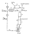
- the limestone (20.9 t / h) having a humidity rate of 6% is introduced into a grinder / dryer 5 where it is ground to a particle size in the fringe of 100 to 400 ⁇ m and dried by heated air in the heat exchanger 4, then the dried limestone is brought into the cyclone 6 where the drying air, the water vapor and the ultra-fines (dust) are extracted from the process at 120 ° C. Dust losses representing approximately 10% of the dry product.
- the dried castine (17.86 t / h) leaves the process head module (comprising the apparatuses 4, 5, 6) and enters the preheating-pre-decarbonation module represented by the heater 2, comprising three cyclones in which the C0 2 leaving reactor 1 yields its sensible heat to lime and is separated from lime.
- the limestone is introduced into reactor 1, in a fluidized bed, (about 3 m in diameter and 4 m high), electrically heated (1115 kWh / t of lime) by carbide resistors of silicon thermostatically controlled at 1150 ° and immersed in the bed, maintained at a temperature of around 950 ° C.
- the pressure drop of the fluidization grid as well as of the dense phase of the fluidized bed is 0.5 bar (50 kPa).
- Quicklime (approx. 10 t / h), powdery and very reactive, is extracted from the fluidized bed and cooled in the CO 2 -CaO 7 heat exchanger, with separate flows, where it transfers part of its heat to the gas carbonic fluidization which arrives in reactor 1 at a temperature close to that of the fluidized bed, which avoids additional energy consumption.
- the C0 2 coming from the fluidization and produced by decarbonation leaves the reactor 1 for the heater 2, where it loses part of its heat given up to limestone, then is directed into the heat exchanger C0 2 -air 4, 'a separate and countercurrent flows, where it is cooled to a temperature of about 40 ° C.
- the C0 2 thus cooled is set in motion by a device known elsewhere, in particular a booster, and carbon dioxide from decarbonation is withdrawn at a point on the device between the outlet of the air / C0 2 4 exchanger and the inlet of the C0 2 / CaO 7 exchanger.
- This withdrawal of C0 2 is very simple, for example using a valve associated with a pressure regulation, for example in the reactor. When the reactor pressure increases, more CO 2 must be withdrawn and vice versa.
- This racking can usefully be connected to a process module used for conditioning the C0 2 for recovery, for example a liquefaction installation of C0 2 .
- the non-withdrawn C0 2 is recycled to the reactor 1, passing beforehand through the exchanger 7.
Landscapes
- Chemical & Material Sciences (AREA)
- Engineering & Computer Science (AREA)
- Ceramic Engineering (AREA)
- Thermal Sciences (AREA)
- General Engineering & Computer Science (AREA)
- Physics & Mathematics (AREA)
- Mechanical Engineering (AREA)
- Dispersion Chemistry (AREA)
- Materials Engineering (AREA)
- Structural Engineering (AREA)
- Organic Chemistry (AREA)
- Devices And Processes Conducted In The Presence Of Fluids And Solid Particles (AREA)
- Treating Waste Gases (AREA)
Description
- La présente invention a pour objet un procédé et un dispositif de décarbonatation de minéraux, notamment de calcaire, par calcination en lit fluidisé.
- La décarbonatation des minéraux nécessite généralement une grande quantité de chaleur étant donné que ces réactions sont fortement endothermiques. C'est pourquoi on avait souvent proposé de la combiner avec des réactions exothermiques, par exemple avec la combustion de substances organiques (comme décrit dans FR-A-1 029 340). Cependant, les divers carbonates ne se décomposent pas tous avec la même facilité, lorsqu'on les porte à la même température. De plus, l'apport de substances supplémentaires complique le contr"ole de la réaction de décarbonatation et nuit à la pureté des produits fabriqués.
- L'invention propose un nouveau procédé et un dispositif qui permettent une plus grande économie d'énergie et, de plus, l'obtention de gaz carbonique très pur valorisable.
- L'invention concerne donc un procédé de décarbonatation de minéraux (ce terme désignant en particulier l'ensemble des roches ou minéraux couramment utilisés industriellement) sous forme de fines particules en lit fluidisé, procédé qui est caractérisé en ce qu'au moins une partie du gaz carbonique produit est recyclée pour être utilisée comme seul gaz de fluidisation, le lit fluidisé étant amené à la température désirée de décarbonatation par apport direct de chaleur au sein du lit fluidisé au moyen de dispositifs électriques.
- Dans la présente invention l'expression "fines particules" désigne des particules ayant une taille de 50 micro mètres à 1 mm.
- L'invention fournit aussi un dispositif pour la mise en oeuvre de ce procédé, comprenant un réacteur de décarbonatation en lit fluidisé muni de moyens de chauffage électriques pour chauffer le réacteur au sein du lit fluidisé, et des moyens pour recycler le gaz carbonique produit comme seul gaz de fluidisation.
- Le lit fluidisé peut consister indifféremment en lit fluidisé simple ou à circulation, ou encore en un lit entraîné analogue à un transport pneumatique. Il peut être isotherme ou à gradient, homogène ou à ségrégation. Sa conception peut être du type silo, tunnel ou multi étagé.
- Selon l'invention, l'apport d'énergie calorifique nécessaire à la réaction est d'origine électrique et est effectué au sein du lit fluidisé. Cet apport d'énergie peut être effectué notamment à l'aide ae résistances électriques plongeant dans le lit fluidisé. Ces résistances peuvent être constituées d'éléments dits thermoplongeurs, notamment d'éléments en carbure de silicium ou en graphite comportant un gainage réfractaire. En variante on peut utiliser une conduction directe dans le médium fluidisé, ou encore d'autres méthodes telles que le chauffage diélectrique ou par micro- ondes.
- La température au sein du lit fluidisé est réglée avantageusement entre la température minimale de décarbonatation à pression atmosphérique et la température de clinkérisation. Dans le cas particulier de la fabrication de chaux, la température du lit fluidisé sera réglée entre 900° et 1000°C (la température des éléments chauffants étant réglée à environ 200°C au-dessus de la température du lit), pour obtenir une chaux très réactive, non clinkérisée sans devoir recourir à des éléments chauffants de surfaces démesurées.
- Le gaz de fluidisation et le gaz issu de la décarbonatation (tous deux du C02) sortent du réacteur et sont séparés des inévitables envols de poudre dans un réchauffeur, par exemple du type cyclone. Après séparation, les poudres sont, dans la mesure du possible, réinjectées dans le réacteur, tandis que dans le réchauffeur le produit entrant (minéral carbonaté) est réchauffé par le C02 à température élevée et, si possible, soumis à un début de décarbonatation avant son introduction dans le réacteur. Comme alternative, le réchauffeur peut être utilisé sous forme de lit fluidisé, en particulier à gradient, par exemple lit fluidisé tunnel.
- Lorsque le produit n'est pas disponible à l'entrée du procédé suffisamment sec et/ou n'a pas la granulométrie souhaitée pour la technologie de réalisation du réacteur, on ajoute un module de tête de procédé comprenant un échangeur de chaleur C02 -air à flux séparés, un broyeur/sécheur de produit entrant (minéral carbonaté) et un séparateur de poudres. L'air peut être introduit dans ce module par un dispositif connu, par exemple par un ventilateur. Cet air réchauffé est soufflé dans le broyeur/sécheur de produit entrant où il remplit le double r*ole d'air de transport pneumatique et d'air de séchage. A la sortie du broyeur/sécheur, le minéral est séparé de l'air, de la vapeur d'eau de séchage et éventuellement des ultra-fins non valorisables dans un dispositif séparateur gaz- poudre, notamment un cyclone. Ainsi le minéral contenant des carbonates pénétre dans le réchauffeur sous forme anhydre et pulvérulente. Le gaz carbonique sortant du réchauffeur de produit entrant, ou le cas échéant de l'échangeur de chaleur C02-air, est soutiré en partie et peut être le cas échéant valorisé, tandis que la partie non soutirée est recyclée dans le réacteur pour servir de gaz de fluidisation.
- Le dispositif peut comprendre aussi un autre échangeur de chaleur C02-produits de réaction, à flux séparés ou non, servant à réchauffer le gaz carbonique recyclé dans le réacteur et à refroidir les produits de réaction sortant du réacteur. Cet échangeur peut notamment avoir une technologie de réalisation apparentée à celle d'un refroidisseur à clinker ou à pluie de particules. Du fait que le C02 est introduit à une température proche de l'ambiante (notamment s'il sort de l'échangeur C02-air), la chaleur sensible des produits de réaction peut être épuisée et totalement, ou presque, récupérée pour réchauffer le C02. Ceci permet de minimiser ou même de supprimer le refroidisseur final avant conditionnement du minéral décarbonaté pour utilisation ou stockage.
- Les principaux avantages du procédé et du dispositif selon l'invention sont :
- - obtention d'un produit décarbonaté très réactif sous forme pulvérulente, par exemple chaux ou magnésie;
- - valorisation aisée du C02 issu de la décarbonatation parce que très pur (c'est pratiquement le seul gaz présent dans le procédé);
- - très bon rendement énergétique de l'installation (le recyclage du C02 et son refroidissement à une température proche de l'ambiante diminuent fortement les pertes de chaleur sensibles);
- - le chauffage électrique du réacteur permet d'obtenir un produit décarbonaté très pur, sans traces d'inertes ou de corps indésirables habituellement contenus dans les combustibles (soufre, azote, potasse, métaux lourds, etc..);
- - la précision d'une régulation d'un chauffage électrique permet de diminuer fortement les risques de clinkérisation du produit et pouvoir valoriser un produit de qualité "chimie fine";
- - la versatilité du procédé permet d'envisaqer des réalisations allant de quelques centaines de kW à plus de 20 MW de puissance installée, ainsi que de faciliter et accélérer les arrêts et démarrages du procédé.
- La description suivante en regard de la figure unique annexée, donnée à titre d'exemple non limitatif, permettra de mieux comprendre comment l'invention peut être réalisée.
- Sur le schéma du procédé et dispositif représentés sur la figure, la castine (20,9 t/h) ayant un taux d'humidité de 6% est introduite dans un broyeur/sécheur 5 où elle est broyée à une granulométrie dans la frange de 100 à 400 µm et séchée par de l'air chauffé dans l'échangeur de chaleur 4, puis la castine séchée est amenée dans le cyclone 6 où l'air de séchage, la vapeur d'eau et les ultra-fins (poussières) sont extraits du processus à 120°C. Les pertes en poussières représentant environ 10% du produit sec. La castine séchée (17,86 t/h) quitte le module de tête de procédé (comprenant les appareils 4, 5, 6) et entre dans le module de préchauffage -pré- décarbonatation représenté par le réchauffeur 2, comprenant trois cyclones dans lesquels le C02 sortant du réacteur 1 cède sa chaleur sensible au calcaire et est séparé du calcaire.
- Une fois réchauffé et pré-décarbonaté, le calcaire est introduit dans le réacteur 1, en lit fluidisé, (environ 3 m de diamètre et 4 m de haut), chauffé électriquement (1115 kWh/t de chaux) par des résistances en carbure de silicium thermostatées à 1150° et immergées dans le lit, maintenu à une température d'environ 950°C. La perte de charge de la grille de fluidisation ainsi que de la phase dense du lit fluidisé est de 0,5 bar (50 kPa).
- La chaux vive (env. 10 t/h), pulvérulente et très réactive, est extraite du lit fluidisé et refroidie dans l'échangeur de chaleur CO2-CaO 7, à flux séparés, où elle cède une partie de sa chaleur au gaz carbonique de fluidisation qui arrive dans le réacteur 1 à une température proche de celle du lit fluidisé, ce qui évite une consommation d'énergie supplémentaire.
- Le C02 provenant de la fluidisation et produit par la décarbonatation quitte le réacteur 1 pour le réchauffeur 2, où il perd une partie de sa chaleur cédée au calcaire, puis est dirigé dans l'échangeur de chaleur C02-air 4, 'a flux séparés et à contre courant, où il est refroidi à une température d'environ 40° C. Le C02 ainsi refroidi est mis en mouvement par un dispositif connu par ailleurs, notamment un surpresseur, et du gaz carbonique issu de la décarbonatation est soutiré en un point du dispositif entre la sortie de l'échangeur air/C02 4 et l'entrée de l'échangeur C02/CaO 7.
- Ce soutirage de C02 se fait très simplement, par exemple à l'aide d'une vanne associée à une régulation de pression, par exemple dans le réacteur. Quand la pression du réacteur s'accroît, il faut soutirer plus de C02 et inversement.
- Ce soutirage peut utilement être connecté à un module du procédé servant au conditionnement du C02 pour sa valorisation, par exemple une installation de liquéfaction de C02. Le C02 non soutiré est recyclé au réacteur 1 en passant préalablement dans l'échangeur 7.
Claims (6)
Applications Claiming Priority (2)
| Application Number | Priority Date | Filing Date | Title |
|---|---|---|---|
| FR8414622 | 1984-09-24 | ||
| FR8414622A FR2570620B1 (fr) | 1984-09-24 | 1984-09-24 | Procede et dispositif de decarbonatation de mineraux par calcination en lit fluidise |
Publications (2)
| Publication Number | Publication Date |
|---|---|
| EP0176433A1 EP0176433A1 (fr) | 1986-04-02 |
| EP0176433B1 true EP0176433B1 (fr) | 1987-12-16 |
Family
ID=9307995
Family Applications (1)
| Application Number | Title | Priority Date | Filing Date |
|---|---|---|---|
| EP85401812A Expired EP0176433B1 (fr) | 1984-09-24 | 1985-09-18 | Procédé et dispositif de décarbonatation de minéraux par calcination en lit fluidisé |
Country Status (5)
| Country | Link |
|---|---|
| US (1) | US4707350A (fr) |
| EP (1) | EP0176433B1 (fr) |
| CA (1) | CA1255070A (fr) |
| DE (1) | DE3561194D1 (fr) |
| FR (1) | FR2570620B1 (fr) |
Families Citing this family (22)
| Publication number | Priority date | Publication date | Assignee | Title |
|---|---|---|---|---|
| WO1990002104A1 (fr) * | 1988-08-19 | 1990-03-08 | Maerz Ofenbau Ag | Procede pour calciner jusqu'a obtention d'une teneur en co2 determinee des roches carbonatees |
| FR2660303B1 (fr) * | 1990-03-27 | 1992-07-17 | Electricite De France | Procede et dispositif de formation d'oxyde de calcium. |
| US5175943A (en) * | 1990-05-23 | 1993-01-05 | E. I. Du Pont De Nemours And Company | Solids feed system and method for feeding fluidized beds |
| GB9626557D0 (en) * | 1996-12-20 | 1997-02-05 | Ecc Int Ltd | The production of slaked lime |
| FR2816935B1 (fr) * | 2000-11-17 | 2003-02-21 | Messer France | Procede et installation d'obtention d'un flux gazeux enrichi en co2 |
| SE0101896L (sv) * | 2001-05-30 | 2002-04-16 | Vattenfall Ab | Förfarande och anordning för kalcinering |
| US6706197B2 (en) * | 2002-01-07 | 2004-03-16 | Palm Beach Aggregates, Inc. | Method for reducing phosphorus in a body of water |
| FR2876782B1 (fr) * | 2004-10-19 | 2007-02-16 | Technip France Sa | Installation et procede de calcination d'une charge minerale contenant un carbonate pour produire un liant hydraulique |
| US9272912B2 (en) * | 2006-08-25 | 2016-03-01 | Robert A. Rossi | Process and system for producing commercial quality carbon dioxide from recausticizing process calcium carbonates |
| JP5120475B2 (ja) * | 2011-03-28 | 2013-01-16 | 三菱マテリアル株式会社 | 生石灰の製造設備並びに消石灰の製造設備および製造方法 |
| TWI484125B (zh) * | 2011-12-23 | 2015-05-11 | 財團法人工業技術研究院 | 迴流懸浮式煅燒爐系統及其使用方法 |
| RU2494056C2 (ru) * | 2011-12-29 | 2013-09-27 | Учреждение Российской академии наук Комплексный научно-исследовательский институт РАН | Способ получения строительных материалов из карбонатных отходов камнедробления |
| TWI516302B (zh) * | 2013-12-11 | 2016-01-11 | 財團法人工業技術研究院 | 循環塔二氧化碳捕獲系統、碳酸化爐、煅燒爐及其使用方法 |
| US11680013B2 (en) | 2019-05-13 | 2023-06-20 | Carmeuse Lime, Inc. | Calciner using recirculated gases |
| CN111348844B (zh) * | 2020-03-12 | 2021-11-26 | 辽宁科大中驰镁建材科技有限公司 | 一种利用低品位高钙菱镁矿制备轻烧氧化镁粉的系统及工艺 |
| PY2173170A (es) | 2020-09-03 | 2022-10-19 | Consejo Superior Investigacion | Proceso para descarbonatación de materiales carbonatados y dispositivo para ello |
| CA3253694A1 (fr) | 2022-03-02 | 2023-09-07 | Flsmidth A/S | Procédé de décarbonatation de matériaux carbonatés et dispositif associé |
| AU2023227080A1 (en) | 2022-03-02 | 2024-08-29 | Carmeuse Technologies | Process for decarbonation of carbonated materials and hydration thereof and device therefof |
| CA3252109A1 (fr) | 2022-03-02 | 2023-09-07 | Carmeuse Technologies | Procédé de décarbonatation de matériaux carbonatés et d'hydratation de ceux-ci et dispositif associé |
| CN116496007B (zh) * | 2023-05-16 | 2024-07-19 | 中冶长天国际工程有限责任公司 | 一种微波分解石灰的工艺方法 |
| WO2026027581A1 (fr) | 2024-07-30 | 2026-02-05 | Carmeuse Technologies SA | Procédé de décarbonatation de matériaux carbonatés |
| US12246991B1 (en) * | 2024-08-27 | 2025-03-11 | Marvin S Keshner | High-efficiency method for converting limestone to slaked lime |
Family Cites Families (20)
| Publication number | Priority date | Publication date | Assignee | Title |
|---|---|---|---|---|
| CH251381A (de) * | 1945-09-07 | 1947-10-31 | Elektrizitaetswerke Lonza | Verfahren zum Brennen von karbonathaltigem Gestein. |
| US2548642A (en) * | 1948-06-11 | 1951-04-10 | Dorr Co | Calcining decrepitating rocks, including limestone |
| US2637545A (en) * | 1948-12-21 | 1953-05-05 | Hicguet Max | Process for the manufacture of magnesia and calcium carbonate |
| FR1024340A (fr) * | 1949-09-08 | 1953-03-31 | Directie Staatsmijnen Nl | Procédé pour préparer du carbonate de soude à partir du bicarbonate de soude avec obtention simultanée d'oxyde de calcium |
| US2738182A (en) * | 1951-07-25 | 1956-03-13 | Dorr Oliver Inc | Method of calcining lime bearing sludges |
| US2774661A (en) * | 1951-08-07 | 1956-12-18 | Dorr Co | Method of heat-treating fines in a coarse solids fluidized bed |
| US2772950A (en) * | 1952-04-01 | 1956-12-04 | Columbia Southern Chem Corp | Calcination of barium carbonate |
| US3332870A (en) * | 1962-10-08 | 1967-07-25 | Mhd Res Inc | Method and apparatus for effecting chemical reactions by means of an electric arc |
| US3271015A (en) * | 1963-01-25 | 1966-09-06 | Harold A Mahony | Process of preparing lime and a system including means for providing a hot gas for use in the process |
| US3595541A (en) * | 1969-05-20 | 1971-07-27 | Nalco Chemical Co | Method and apparatus for treating particulate solids in a fluidized bed |
| GB1390351A (en) * | 1971-02-16 | 1975-04-09 | Tetronics Research Dev Co Ltd | High temperature treatment of materials |
| US3796791A (en) * | 1971-12-20 | 1974-03-12 | Nichols Eng & Res Corp | Process for reclaiming limestone mud |
| US3862294A (en) * | 1972-04-10 | 1975-01-21 | Donald Spencer Engelhart | Method for flash calcining inorganic materials |
| US3829391A (en) * | 1972-09-19 | 1974-08-13 | Atomic Energy Commission | Submerged arc crystal growth process for growing transparent alkaline earth oxide single crystals |
| DE2524540C2 (de) * | 1975-06-03 | 1986-04-24 | Metallgesellschaft Ag, 6000 Frankfurt | Verfahren zur Durchführung endothermer Prozesse |
| US4321239A (en) * | 1980-09-04 | 1982-03-23 | Bildjukevich Viktor L | Method of thermal treatment of a carbonate suspension |
| US4389381A (en) * | 1980-09-19 | 1983-06-21 | Battelle Development Corporation | Limestone calcination |
| FR2507919B1 (fr) * | 1981-06-19 | 1986-12-05 | Electricite De France | Procede et dispositif pour la mise en oeuvre de reactions endothermiques dans une enceinte a lit fluidise |
| DE3131023C2 (de) * | 1981-08-05 | 1985-12-05 | Klöckner-Humboldt-Deutz AG, 5000 Köln | Verfahren und Vorrichtung zum Brennen von Kalk |
| EP0140915B1 (fr) * | 1983-03-18 | 1987-07-08 | Southwest Research Institute | Procede catalytique pour une decarboxylation acceleree du carbonate de calcium et melange destine a cet effet |
-
1984
- 1984-09-24 FR FR8414622A patent/FR2570620B1/fr not_active Expired
-
1985
- 1985-09-18 DE DE8585401812T patent/DE3561194D1/de not_active Expired
- 1985-09-18 EP EP85401812A patent/EP0176433B1/fr not_active Expired
- 1985-09-23 CA CA000491333A patent/CA1255070A/fr not_active Expired
- 1985-09-24 US US06/779,754 patent/US4707350A/en not_active Expired - Lifetime
Also Published As
| Publication number | Publication date |
|---|---|
| FR2570620A1 (fr) | 1986-03-28 |
| DE3561194D1 (en) | 1988-01-28 |
| US4707350A (en) | 1987-11-17 |
| CA1255070A (fr) | 1989-06-06 |
| FR2570620B1 (fr) | 1988-10-28 |
| EP0176433A1 (fr) | 1986-04-02 |
Similar Documents
| Publication | Publication Date | Title |
|---|---|---|
| EP0176433A1 (fr) | Procédé et dispositif de décarbonatation de minéraux par calcination en lit fluidisé | |
| KR102537727B1 (ko) | 규산염 광물로부터 리튬의 회수 | |
| US10829413B2 (en) | Process and apparatus for manufacture of calcined compounds for the production of calcined products | |
| EP2692709B1 (fr) | Installation de fabrication et procédé de fabrication de chaux éteinte | |
| SA110310076B1 (ar) | عملية ووحدة صناعية لإنتاج أكسيد فلزي من أملاح فلزية | |
| JP2023551876A (ja) | 材料の焼成のためのプロセス及び方法 | |
| SE517124C2 (sv) | Förfarande och anordning för kalcinering | |
| JP7821802B2 (ja) | 石油コークスの処理装置、処理方法および処理システム | |
| US7264781B2 (en) | Calcining plant and method | |
| US3498594A (en) | Cement burning process and apparatus | |
| JP7773797B2 (ja) | 粉末のパイロ処理方法 | |
| US3603569A (en) | Kiln preheat and drying section | |
| US3024082A (en) | Lithium chloride production | |
| EP4532433A1 (fr) | Système et procédé de calcination | |
| JP2878147B2 (ja) | セメントクリンカ又はそれに類似するものを燃焼するための乾式ロータリーキルンの前接続段としての浮遊ガス熱交換器 | |
| JPS58893B2 (ja) | 粉粒状物質の焼成・冷却方法およびその装置 | |
| FR2482578A1 (fr) | Procede pour refroidir le carbure de calcium fondu et appareillage pour sa mise en oeuvre | |
| FR2584308A1 (fr) | Procede et dispositif de decarbonatation de mineraux par calcination en lit fluidise | |
| CN115557507B (zh) | 从含有氯硅烷的渣浆中分离硅粉的方法、系统及其用途 | |
| JPH08271143A (ja) | 微粒子材料の乾燥方法 | |
| EP4532434A1 (fr) | Procédé et agencement de récupération de chaleur dans un système de calcination | |
| JP2024140141A (ja) | 二酸化炭素の回収設備及び回収方法、二酸化炭素の貯留方法、セメントクリンカの製造システム及び製造方法、並びにドライアイスの製造方法 | |
| CN121318197A (zh) | 一种基于水泥熟料生产线制备热生料系统 | |
| JP2024140140A (ja) | 二酸化炭素の回収設備及び回収方法、二酸化炭素の貯留方法、セメントクリンカの製造システム及び製造方法、並びにドライアイスの製造方法 | |
| BE523158A (fr) |
Legal Events
| Date | Code | Title | Description |
|---|---|---|---|
| PUAI | Public reference made under article 153(3) epc to a published international application that has entered the european phase |
Free format text: ORIGINAL CODE: 0009012 |
|
| AK | Designated contracting states |
Kind code of ref document: A1 Designated state(s): BE DE FR GB IT LU NL SE |
|
| 17P | Request for examination filed |
Effective date: 19860228 |
|
| 17Q | First examination report despatched |
Effective date: 19861121 |
|
| ITF | It: translation for a ep patent filed | ||
| GRAA | (expected) grant |
Free format text: ORIGINAL CODE: 0009210 |
|
| AK | Designated contracting states |
Kind code of ref document: B1 Designated state(s): BE DE FR GB IT LU NL SE |
|
| GBT | Gb: translation of ep patent filed (gb section 77(6)(a)/1977) | ||
| REF | Corresponds to: |
Ref document number: 3561194 Country of ref document: DE Date of ref document: 19880128 |
|
| PLBE | No opposition filed within time limit |
Free format text: ORIGINAL CODE: 0009261 |
|
| STAA | Information on the status of an ep patent application or granted ep patent |
Free format text: STATUS: NO OPPOSITION FILED WITHIN TIME LIMIT |
|
| 26N | No opposition filed | ||
| ITTA | It: last paid annual fee | ||
| EPTA | Lu: last paid annual fee | ||
| EAL | Se: european patent in force in sweden |
Ref document number: 85401812.4 |
|
| REG | Reference to a national code |
Ref country code: GB Ref legal event code: IF02 |
|
| PGFP | Annual fee paid to national office [announced via postgrant information from national office to epo] |
Ref country code: FR Payment date: 20020726 Year of fee payment: 18 |
|
| PGFP | Annual fee paid to national office [announced via postgrant information from national office to epo] |
Ref country code: NL Payment date: 20020815 Year of fee payment: 18 |
|
| PGFP | Annual fee paid to national office [announced via postgrant information from national office to epo] |
Ref country code: SE Payment date: 20020816 Year of fee payment: 18 |
|
| PGFP | Annual fee paid to national office [announced via postgrant information from national office to epo] |
Ref country code: GB Payment date: 20020910 Year of fee payment: 18 |
|
| PGFP | Annual fee paid to national office [announced via postgrant information from national office to epo] |
Ref country code: LU Payment date: 20020911 Year of fee payment: 18 Ref country code: DE Payment date: 20020911 Year of fee payment: 18 |
|
| PGFP | Annual fee paid to national office [announced via postgrant information from national office to epo] |
Ref country code: BE Payment date: 20021011 Year of fee payment: 18 |
|
| PG25 | Lapsed in a contracting state [announced via postgrant information from national office to epo] |
Ref country code: LU Free format text: LAPSE BECAUSE OF NON-PAYMENT OF DUE FEES Effective date: 20030918 Ref country code: GB Free format text: LAPSE BECAUSE OF NON-PAYMENT OF DUE FEES Effective date: 20030918 |
|
| PG25 | Lapsed in a contracting state [announced via postgrant information from national office to epo] |
Ref country code: SE Free format text: LAPSE BECAUSE OF NON-PAYMENT OF DUE FEES Effective date: 20030919 |
|
| PG25 | Lapsed in a contracting state [announced via postgrant information from national office to epo] |
Ref country code: BE Free format text: LAPSE BECAUSE OF NON-PAYMENT OF DUE FEES Effective date: 20030930 |
|
| BERE | Be: lapsed |
Owner name: *ELECTRICITE DE FRANCE SERVICE NATIONAL Effective date: 20030930 |
|
| PG25 | Lapsed in a contracting state [announced via postgrant information from national office to epo] |
Ref country code: NL Free format text: LAPSE BECAUSE OF NON-PAYMENT OF DUE FEES Effective date: 20040401 Ref country code: DE Free format text: LAPSE BECAUSE OF NON-PAYMENT OF DUE FEES Effective date: 20040401 |
|
| EUG | Se: european patent has lapsed | ||
| GBPC | Gb: european patent ceased through non-payment of renewal fee |
Effective date: 20030918 |
|
| PG25 | Lapsed in a contracting state [announced via postgrant information from national office to epo] |
Ref country code: FR Free format text: LAPSE BECAUSE OF NON-PAYMENT OF DUE FEES Effective date: 20040528 |
|
| NLV4 | Nl: lapsed or anulled due to non-payment of the annual fee |
Effective date: 20040401 |
|
| REG | Reference to a national code |
Ref country code: FR Ref legal event code: ST |