EP0175673A1 - Dispositif de changement pour pièce de fixation d'une tête de grappin - Google Patents
Dispositif de changement pour pièce de fixation d'une tête de grappin Download PDFInfo
- Publication number
- EP0175673A1 EP0175673A1 EP85890159A EP85890159A EP0175673A1 EP 0175673 A1 EP0175673 A1 EP 0175673A1 EP 85890159 A EP85890159 A EP 85890159A EP 85890159 A EP85890159 A EP 85890159A EP 0175673 A1 EP0175673 A1 EP 0175673A1
- Authority
- EP
- European Patent Office
- Prior art keywords
- housing
- locking
- devices
- openings
- clamping
- Prior art date
- Legal status (The legal status is an assumption and is not a legal conclusion. Google has not performed a legal analysis and makes no representation as to the accuracy of the status listed.)
- Granted
Links
- 238000010168 coupling process Methods 0.000 claims abstract description 51
- 230000008878 coupling Effects 0.000 claims abstract description 48
- 238000005859 coupling reaction Methods 0.000 claims abstract description 48
- 238000003780 insertion Methods 0.000 description 9
- 230000037431 insertion Effects 0.000 description 9
- 238000006243 chemical reaction Methods 0.000 description 1
- 230000007812 deficiency Effects 0.000 description 1
- 238000000034 method Methods 0.000 description 1
Images
Classifications
-
- B—PERFORMING OPERATIONS; TRANSPORTING
- B25—HAND TOOLS; PORTABLE POWER-DRIVEN TOOLS; MANIPULATORS
- B25J—MANIPULATORS; CHAMBERS PROVIDED WITH MANIPULATION DEVICES
- B25J15/00—Gripping heads and other end effectors
- B25J15/04—Gripping heads and other end effectors with provision for the remote detachment or exchange of the head or parts thereof
- B25J15/0491—Gripping heads and other end effectors with provision for the remote detachment or exchange of the head or parts thereof comprising end-effector racks
-
- B—PERFORMING OPERATIONS; TRANSPORTING
- B23—MACHINE TOOLS; METAL-WORKING NOT OTHERWISE PROVIDED FOR
- B23Q—DETAILS, COMPONENTS, OR ACCESSORIES FOR MACHINE TOOLS, e.g. ARRANGEMENTS FOR COPYING OR CONTROLLING; MACHINE TOOLS IN GENERAL CHARACTERISED BY THE CONSTRUCTION OF PARTICULAR DETAILS OR COMPONENTS; COMBINATIONS OR ASSOCIATIONS OF METAL-WORKING MACHINES, NOT DIRECTED TO A PARTICULAR RESULT
- B23Q7/00—Arrangements for handling work specially combined with or arranged in, or specially adapted for use in connection with, machine tools, e.g. for conveying, loading, positioning, discharging, sorting
- B23Q7/04—Arrangements for handling work specially combined with or arranged in, or specially adapted for use in connection with, machine tools, e.g. for conveying, loading, positioning, discharging, sorting by means of grippers
- B23Q7/043—Construction of the grippers
Definitions
- the invention relates to a device for changing the workpiece clamping device of a gripper head, consisting of an adjustable support arm for the gripper head, which has at least one connecting flange for at least one clamping device, a separate housing for the clamping device, which can be coupled to a drive in the gripper head Actuator for the clamping tools, and from a magazine with brackets for various clamping devices.
- Gripper heads for loading and unloading machine tools have at least one clamping device with gripping tools for the workpieces, which can be conveyed back and forth between at least one workpiece storage device and the machine tool by means of the gripper head which can be adjusted by means of a support arm. Since, on the one hand, the adjustment path of the gripping tools of the clamping devices is limited and, on the other hand, different gripping tools are required, for example for clamping shafts or chuck parts, it is necessary to convert the gripper heads accordingly.
- gripper heads with two diametrically opposed clamping devices DE-OS 30 43 687
- the housing with the two clamping devices is on one connection flange of the gripper head is exchangeably fastened, with the fastening of the housing of the clamping devices on the connecting flange of the actuating drive accommodated in this housing for the gripping tools being coupled independently with a drive in the gripper head.
- the invention is therefore based on the object of avoiding these deficiencies and of creating a device for mechanically changing the workpiece clamping device of a gripper head.
- This device should be comparatively simple and not require any additional drives.
- the invention achieves the object in that the connecting flange bears vertically projecting coupling bolts which engage in corresponding receiving openings in the housing of the clamping device, that the housing of the clamping device provides a locking device for each coupling pin with a counter to the force of a Has closing spring from the outside adjustable closure piece and that the magazine in the area of the brackets for the tensioning devices forms and stops for the locking pieces of the locking devices.
- the coupling bolts perpendicular to the connecting flange, which engage in corresponding receiving openings in the housing of the tensioning device, allow the respective tensioning device to be easily pushed onto the coupling bolts because the support arm for the gripper head only has to be adjusted in the direction of these coupling bolts.
- the locking device holds the coupling bolts inserted into the receiving openings, so that only the drive already provided for the movement of the support arm is required for the coupling process.
- the lock itself is carried out via the closing spring, which presses the adjustable closure piece of the locking device into the closed position.
- a prerequisite for this simple coupling process, however, is that when a clamping device is coupled to the gripper head, the locking device is in an unlocked position.
- the magazine is provided with positioning and holding stops for the locking pieces of the locking devices. If a clamping device is inserted into the holder of the magazine, the actuating and holding stops press on the locking pieces of the locking device, which, due to the relative movement between the clamping device and the actuating and holding stops, are pressed against the force of the closing spring into the unlocking position and held in this unlocking position will.
- the locking devices are thus automatically unlocked when the clamping devices are inserted into the holders of the magazine via the set and hold stops provided for them, so that when the clamping devices are coupled to the connecting flange, the coupling bolts can freely intervene in the receiving openings.
- the holding devices of the magazine form guides for the clamping devices running transversely to the direction of adjustment of the locking pieces of the taken-up clamping devices.
- the tensioning devices are relentlessly supported in these guides, so that the locking pieces are inevitably in the unlocked position by the setting and holding stops are held, because the direction of adjustment of the closure pieces extends transversely to the support of the tensioning devices.
- the guides for the tensioning devices consist of guide slots for guide pins provided on opposite side walls of the housing of the tensioning devices.
- these guide pins engage in the guide slots provided, which represent a positive guide for the housing of the clamping devices. This also ensures the relative movement between the actuating and holding stops and the housing of the tensioning devices required for unlocking the locking pieces by simple means.
- the locking pieces of the locking devices can be adjustable via driver pins which run parallel to the guide pins of the housing of the tensioning device. These driver pins are forced into the slots forming the actuating and holding stops, the actuating movement of the locking pieces depending on the change in distance measured in the direction of the adjusting movement of the locking pieces between the guide surfaces of the guide slots for the guide pins and the guide surfaces of the slots for the driver pins.
- the movement of the closure pieces can be made largely independent of the insertion movement of the clamping devices in the holders of the magazine if the positioning and holding stops for the closure pieces of the.
- Locking device have a run-on slope, which determines the actuating movement of the closure pieces.
- the adjustment direction of the closure pieces depends only on the possible directions of movement of the gripper head, because of the movement of the gripper head Compared to the magazine, the locking pieces are adjusted, it is particularly advantageous to slide the locking pieces of the locking devices parallel to the axis of the receiving openings for the coupling pins. In this case, the clamping devices can be inserted into the holders of the magazine in the coupling direction.
- the receiving openings for the coupling bolts can be formed by a housing-fixed sleeve which has openings for balls which engage in an annular groove of the coupling bolt and form locking bodies
- the closure piece having a bush which is axially displaceably mounted on the sleeve comprises, which is held by the closing spring in a closed position covering the openings for the balls and can be pushed away from the openings against the force of the closing spring.
- the bushing which results in the closure piece covers the openings in the housing-fixed sleeve, so that the balls provided in the openings cannot emerge from the annular groove of the coupling bolt and hold the coupling bolt in the axial direction.
- the balls can move radially outward through the openings in the event of an axial bolt movement.
- the coupling pin is therefore released.
- the balls are again pressed through the openings against the annular groove of the bolt and held in the engaged position.
- a sleeve fixed in the housing Stamp be slidably mounted, which can be inserted through the coupling bolt into the receiving opening against the force of a spring from a stop position covering the openings for the balls. In its stop position, the stamp covers the openings in the housing-fixed sleeve from the inside, so that the balls cannot fall into the sleeve.
- the plunger Due to the coupling pin engaging in the receiving opening, the plunger is pressed against the spring force into the receiving opening, the openings in the sleeve initially being covered by the coupling pin until the coupling pin is fully inserted into the receiving opening and the openings are in the area of the annular groove.
- the plunger is pressed onto the coupling bolt until the stop position is reached, in which the openings are covered again.
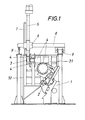
- a lathe 1 is to be loaded and unloaded, the chuck of which is designated by 2.
- a gripper head 3 with two workpiece clamping devices 4 is provided, which is arranged on a support arm 5.
- This support arm 5 is guided vertically displaceably in a cross slide 6 and can be raised and lowered by means of a cylinder 7.
- the cross slide 6 is supported on a longitudinal slide 8 which can be moved on guide tracks 9 in the direction of the main axis of the lathe 1.
- the gripper head 3 can thus be moved in three mutually perpendicular axes.
- clamping devices 4 can be pivoted about l80 'about a common axis of rotation running parallel to the adjustment direction of the cross slide 6, in order to remove the already machined workpiece from the chuck 2 of the lathe 1 with one of the two clamping devices 4 and then one with the help of the other clamping device to be able to insert the workpiece to be machined into the chuck 2 without having to adjust the gripper head 3 vertically via the support arm 5.
- the clamping devices must be adapted to the workpiece geometry.
- the gripper head 3 must therefore be converted for processing such different workpieces by replacing the clamping devices 4.
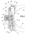
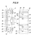
- the gripper head 3 according to FIG. 2 has a connecting flange 10 which bears vertically projecting coupling bolts 11. These coupling bolts 11 engage in receiving openings 12 of the housing 13 of the tensioning device 4 and are held in the receiving openings 12 by a releasable locking device 14 (FIG. 4).
- the actuator of the clamping devices 4 When connecting the clamping devices 4 to the gripper head 3, the actuator of the clamping devices 4 must of course also be coupled to the drive of the gripper head 3.
- the actuator for the radially displaceably mounted in the housing 13 jaws 15, which Carrying gripper tools 16 interchangeably, according to the exemplary embodiment, consists of a plane spiral disk 17 rotatably mounted in the housing 13, which engages in a corresponding plane spiral section of the clamping jaws 15 and can be driven via a connecting shaft 18.
- This connecting shaft 18 is designed as a polygonal shaft and forms a plug-in coupling with a plug sleeve 19 of opposite shape.
- the receptacle 19 is non-rotatably but axially displaceably inserted in a hollow output shaft 20 of the gripper head 3 and acted upon by a spring 21. If the rotational position of the connecting shaft 18 does not match the rotational position of the plug-in sleeve 19 when the clamping device 4 is coupled to the connecting flange 10, then the plug-in sleeve 19 is inserted into the output shaft 20 of the gripper head 3 against the force of the spring 21 without inserting the coupling bolt 11 in the receiving openings 12 and thus to hinder the connection process.
- the plug-in sleeve 19 is pushed onto the connecting shaft 18 by the spring 21 and a positive drive connection is established as soon as mutually overlapping rotational positions are reached.
- the tensioning device 4 can then be adjusted in both directions via the output shaft 20.
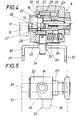
- the locking device 14 for the coupling bolts 11 engaging in the receiving openings 12 consists of a locking piece 22 which is mounted axially displaceably on a sleeve 23 fixed to the housing and which is acted upon by a locking spring 24 in the closing direction of the locking device.
- the locking piece comprises a bushing 25 which interacts with balls 26 forming locking bodies. These balls 26 are inserted into openings 27 of the sleeve 23 resulting in the receiving openings 12 and engage in the locking position in an annular groove 28 of the coupling bolts 11. In this locking position, the bushing 25 covers the openings 27 in the sleeve 23, as is shown in the lower part of FIG. 4.
- a stamp 29 is displaceably guided within the sleeve 23 and is held in a stop position by a spring 30 in which it covers the openings 27.
- This stamp 29 is used for Inserting the coupling pin 11 into the receiving opening 12 pushed back against the force of the spring 30, the balls 26 coming into the area of the annular groove 28, as can be seen in the lower part of Fig. 4. If the locking piece 22 is released in this coupling position, the closing spring 24 presses the bushing 25 into the closed position covering the openings 27, in which the coupling pin 11 in the receiving opening 1 2 is locked.
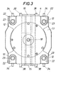
- the clamping devices 4 provided for replacement are accommodated in corresponding holders 31 of a magazine 32.
- This magazine 32 forms in the area of the brackets 31 adjusting and holding stops 33 for the locking pieces 22, which are adjusted by the adjusting and holding stops 33 when the respective clamping device 4 is inserted into the brackets, specifically by means of driver pins 34 inserted into the locking pieces 22.
- the arrangement is such that the actuating and holding stops are formed by guide slots 35 which have a run-on slope 36 for the driving pins 34.
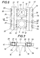
- the brackets themselves are provided with guide slots 37 for guide pins 38, which run parallel to the driver pins 34 and are arranged laterally on the housing 13 of the clamping devices 4.
- the guide slots 37 form a transverse to the direction of adjustment of the locking pieces 22 of the recorded clamping devices extending guide, so that when the tensioning devices 4 are inserted into these guide slots 37, the driver pins 34 of the locking pieces 22 are not only adjusted along the bevel 36 against the force of the closing spring 24 in the unlocking direction, but are also held in the unlocking position.
- the run-up slope 36 thus forms the actuating part and the adjoining parallel section of the guide slot 35 the holding part of the actuating and holding stops 33. Since the actuating movement of the locking pieces 22 runs in the coupling direction, the tensioning device with the aid of the gripper head 3 must be inserted into the guide slots 36 transversely to the coupling direction , 37 are introduced.
- the guide slots 36, 37 are therefore accessible via insertion slots 39 in the brackets 31. These insertion slots are open on both sides, so that the clamping devices can also be removed and inserted from the side facing away from the gripper head.
- the coupling bolts can be pulled out of the Receiving openings or the insertion of the coupling bolts into the receiving openings of the tensioning devices no difficulties, because the tensioning devices are supported accordingly in this direction.
- the movement of the gripper head 3 in two mutually perpendicular directions in accordance with the course of the insertion slots 39 and the guide slots 37 extending therefrom can be carried out without problems in the case of the gripper bearing, which is adjustable in three axes.
- brackets 31 consist of profiles which are U-shaped in cross section and which are fastened on opposite sides of uprights 41 and which Form guide slots for the clamping devices, as can be seen in FIGS. 6 and 7.
- the guide pins 38 can have a different diameter than the driver pins 34, the insertion slots 39 having opening widths corresponding to these diameters.
- the gripper head is provided with a connecting plate 10 and coupling bolts 11, not only clamping devices 4, but also other tools or tool parts can be connected to the gripper head, which are required, for example, to convert the lathe. For this purpose, these conversion parts only need to be provided with corresponding locking devices 14. With the help of such a gripper head, z. B. a chuck change can be carried out mechanically. If the two clamping devices 4 form a structural unit, this structural unit can also be replaced instead of the two clamping devices.
Landscapes
- Engineering & Computer Science (AREA)
- Mechanical Engineering (AREA)
- Robotics (AREA)
- Mounting, Exchange, And Manufacturing Of Dies (AREA)
- Jigs For Machine Tools (AREA)
Applications Claiming Priority (2)
| Application Number | Priority Date | Filing Date | Title |
|---|---|---|---|
| AT2959/84 | 1984-09-18 | ||
| AT0295984A AT382335B (de) | 1984-09-18 | 1984-09-18 | Vorrichtung zum wechseln der werkstueck-spanneinrichtung eines greiferkopfes |
Publications (2)
| Publication Number | Publication Date |
|---|---|
| EP0175673A1 true EP0175673A1 (fr) | 1986-03-26 |
| EP0175673B1 EP0175673B1 (fr) | 1988-10-19 |
Family
ID=3543091
Family Applications (1)
| Application Number | Title | Priority Date | Filing Date |
|---|---|---|---|
| EP85890159A Expired EP0175673B1 (fr) | 1984-09-18 | 1985-07-19 | Dispositif de changement pour pièce de fixation d'une tête de grappin |
Country Status (3)
| Country | Link |
|---|---|
| EP (1) | EP0175673B1 (fr) |
| AT (1) | AT382335B (fr) |
| DE (1) | DE3565646D1 (fr) |
Cited By (1)
| Publication number | Priority date | Publication date | Assignee | Title |
|---|---|---|---|---|
| EP0288148A1 (fr) * | 1987-04-16 | 1988-10-26 | General Motors Corporation | Raccordement déconnectable entre un outil et une machine |
Families Citing this family (1)
| Publication number | Priority date | Publication date | Assignee | Title |
|---|---|---|---|---|
| CN117583634B (zh) * | 2023-11-21 | 2024-05-14 | 无锡高卓流体设备有限公司 | 一种管道泵端部法兰钻孔装置 |
Citations (2)
| Publication number | Priority date | Publication date | Assignee | Title |
|---|---|---|---|---|
| FR2542243A1 (fr) * | 1983-03-11 | 1984-09-14 | Pont A Mousson | Porte-outil pour robot industriel |
| DD214330A1 (de) * | 1983-03-16 | 1984-10-10 | Inst F Rationalis D Elektrotec | Greiferwechselvorrichtung mit sensorschnittstelle und luftzufuehrung fuer industrieroboter |
Family Cites Families (1)
| Publication number | Priority date | Publication date | Assignee | Title |
|---|---|---|---|---|
| FR2533159A1 (fr) * | 1982-09-20 | 1984-03-23 | Calhene | Dispositif de raccordement deconnectable d'une genouillere sur un bras esclave de telemanipulateur et support de deconnexion correspondant |
-
1984
- 1984-09-18 AT AT0295984A patent/AT382335B/de not_active IP Right Cessation
-
1985
- 1985-07-19 EP EP85890159A patent/EP0175673B1/fr not_active Expired
- 1985-07-19 DE DE8585890159T patent/DE3565646D1/de not_active Expired
Patent Citations (2)
| Publication number | Priority date | Publication date | Assignee | Title |
|---|---|---|---|---|
| FR2542243A1 (fr) * | 1983-03-11 | 1984-09-14 | Pont A Mousson | Porte-outil pour robot industriel |
| DD214330A1 (de) * | 1983-03-16 | 1984-10-10 | Inst F Rationalis D Elektrotec | Greiferwechselvorrichtung mit sensorschnittstelle und luftzufuehrung fuer industrieroboter |
Cited By (1)
| Publication number | Priority date | Publication date | Assignee | Title |
|---|---|---|---|---|
| EP0288148A1 (fr) * | 1987-04-16 | 1988-10-26 | General Motors Corporation | Raccordement déconnectable entre un outil et une machine |
Also Published As
| Publication number | Publication date |
|---|---|
| ATA295984A (de) | 1986-07-15 |
| EP0175673B1 (fr) | 1988-10-19 |
| DE3565646D1 (en) | 1988-11-24 |
| AT382335B (de) | 1987-02-10 |
Similar Documents
| Publication | Publication Date | Title |
|---|---|---|
| EP3600798B1 (fr) | Système de préhension et de positionnement servant au transport d'un dispositif de serrage entre différentes positions | |
| EP0117557B1 (fr) | Palette porte-pièces sur des machines-outils | |
| DE2808796C2 (de) | Vorrichtung zum Überführen von Werkzeugen in einer Werkzeugmaschine | |
| DE8526544U1 (de) | Werkzeugmaschine | |
| DE2325629C2 (de) | Werkzeugmagazin für eine Werkzeugmaschine | |
| CH623257A5 (fr) | ||
| DE3610317A1 (de) | Automatische zentrier- und greifvorrichtung | |
| DE60012158T2 (de) | Verfahren zur beibehaltung der position eines werkstückes in einem montageplatz | |
| DE3531160A1 (de) | Werkzeugwechsler fuer eine werkzeugmaschine | |
| DE1477578B2 (de) | Numerisch gesteuerte werkzeugmaschine | |
| DE3937570C2 (fr) | ||
| DE102021117229B4 (de) | Spannvorrichtung und Verfahren zur Handhabung eines Werkstücks | |
| EP0742081A2 (fr) | Etan universel de précision pour une machine-outil | |
| EP0791427A1 (fr) | Dispositif de préhension pour pièces | |
| EP0157728A1 (fr) | Machine à tourner | |
| DE3203891A1 (de) | Werkzeugmaschine zum den werkstoff abhebenden bearbeiten von werkstuecken | |
| DE3010934C2 (fr) | ||
| EP0195184B1 (fr) | Dispositif d'interchange de mors | |
| DE1502010A1 (de) | Werkzeugmaschine mit automatischem Werkzeugwechsel | |
| EP0913226B1 (fr) | Centre d'usinage dans lequel les porte-pièces sont pourvus d'un module de couplage ainsi que d'une connexion multiple | |
| DE10122049B4 (de) | Vorrichtung zum Verriegeln von zwei miteinander zu koppelnden Einrichtungen, insbesondere eines Testkopfs und einer Prüfeinrichtung | |
| EP0175673B1 (fr) | Dispositif de changement pour pièce de fixation d'une tête de grappin | |
| DE4124228C2 (fr) | ||
| EP0637277B1 (fr) | Dispositif pour l'usinage de metaux par enlevement de copeaux | |
| EP0283810B1 (fr) | Presse transfert |
Legal Events
| Date | Code | Title | Description |
|---|---|---|---|
| PUAI | Public reference made under article 153(3) epc to a published international application that has entered the european phase |
Free format text: ORIGINAL CODE: 0009012 |
|
| AK | Designated contracting states |
Kind code of ref document: A1 Designated state(s): BE CH DE FR GB IT LI LU NL SE |
|
| 17P | Request for examination filed |
Effective date: 19860317 |
|
| 17Q | First examination report despatched |
Effective date: 19870716 |
|
| RAP1 | Party data changed (applicant data changed or rights of an application transferred) |
Owner name: VOEST-ALPINE INDUSTRIEANLAGENBAU GESELLSCHAFT M.B Owner name: VOEST-ALPINE AKTIENGESELLSCHAFT |
|
| RAP1 | Party data changed (applicant data changed or rights of an application transferred) |
Owner name: VOEST-ALPINE MASCHINENBAU GESELLSCHAFT M.B.H. |
|
| GRAA | (expected) grant |
Free format text: ORIGINAL CODE: 0009210 |
|
| AK | Designated contracting states |
Kind code of ref document: B1 Designated state(s): BE CH DE FR GB IT LI NL SE |
|
| REF | Corresponds to: |
Ref document number: 3565646 Country of ref document: DE Date of ref document: 19881124 |
|
| GBT | Gb: translation of ep patent filed (gb section 77(6)(a)/1977) | ||
| ITF | It: translation for a ep patent filed | ||
| ET | Fr: translation filed | ||
| PGFP | Annual fee paid to national office [announced via postgrant information from national office to epo] |
Ref country code: FR Payment date: 19890616 Year of fee payment: 5 |
|
| PGFP | Annual fee paid to national office [announced via postgrant information from national office to epo] |
Ref country code: SE Payment date: 19890619 Year of fee payment: 5 Ref country code: DE Payment date: 19890619 Year of fee payment: 5 Ref country code: CH Payment date: 19890619 Year of fee payment: 5 Ref country code: BE Payment date: 19890619 Year of fee payment: 5 |
|
| PGFP | Annual fee paid to national office [announced via postgrant information from national office to epo] |
Ref country code: GB Payment date: 19890630 Year of fee payment: 5 |
|
| ITTA | It: last paid annual fee | ||
| PGFP | Annual fee paid to national office [announced via postgrant information from national office to epo] |
Ref country code: NL Payment date: 19890731 Year of fee payment: 5 |
|
| PLBE | No opposition filed within time limit |
Free format text: ORIGINAL CODE: 0009261 |
|
| STAA | Information on the status of an ep patent application or granted ep patent |
Free format text: STATUS: NO OPPOSITION FILED WITHIN TIME LIMIT |
|
| 26N | No opposition filed | ||
| PG25 | Lapsed in a contracting state [announced via postgrant information from national office to epo] |
Ref country code: GB Effective date: 19900719 |
|
| PG25 | Lapsed in a contracting state [announced via postgrant information from national office to epo] |
Ref country code: SE Effective date: 19900720 |
|
| PG25 | Lapsed in a contracting state [announced via postgrant information from national office to epo] |
Ref country code: LI Effective date: 19900731 Ref country code: CH Effective date: 19900731 Ref country code: BE Effective date: 19900731 |
|
| BERE | Be: lapsed |
Owner name: VOEST-ALPINE MASCHINENBAU G.M.B.H. Effective date: 19900731 |
|
| PG25 | Lapsed in a contracting state [announced via postgrant information from national office to epo] |
Ref country code: NL Effective date: 19910201 |
|
| NLV4 | Nl: lapsed or anulled due to non-payment of the annual fee | ||
| GBPC | Gb: european patent ceased through non-payment of renewal fee | ||
| REG | Reference to a national code |
Ref country code: CH Ref legal event code: PL |
|
| PG25 | Lapsed in a contracting state [announced via postgrant information from national office to epo] |
Ref country code: FR Effective date: 19910329 |
|
| PG25 | Lapsed in a contracting state [announced via postgrant information from national office to epo] |
Ref country code: DE Effective date: 19910403 |
|
| REG | Reference to a national code |
Ref country code: FR Ref legal event code: ST |
|
| EUG | Se: european patent has lapsed |
Ref document number: 85890159.8 Effective date: 19910402 |