EP0175396B1 - Auslaufkonstruktion für Drainagerohre mit die Böschung schützenden Eigenschaften - Google Patents
Auslaufkonstruktion für Drainagerohre mit die Böschung schützenden Eigenschaften Download PDFInfo
- Publication number
- EP0175396B1 EP0175396B1 EP85200943A EP85200943A EP0175396B1 EP 0175396 B1 EP0175396 B1 EP 0175396B1 EP 85200943 A EP85200943 A EP 85200943A EP 85200943 A EP85200943 A EP 85200943A EP 0175396 B1 EP0175396 B1 EP 0175396B1
- Authority
- EP
- European Patent Office
- Prior art keywords
- gutter
- shaped member
- tube
- talus
- ditch
- Prior art date
- Legal status (The legal status is an assumption and is not a legal conclusion. Google has not performed a legal analysis and makes no representation as to the accuracy of the status listed.)
- Expired
Links
- 230000002633 protecting effect Effects 0.000 title claims description 5
- 210000004233 talus Anatomy 0.000 title abstract description 15
- 238000010276 construction Methods 0.000 title abstract description 3
- 230000008878 coupling Effects 0.000 claims description 20
- 238000010168 coupling process Methods 0.000 claims description 20
- 238000005859 coupling reaction Methods 0.000 claims description 20
- XLYOFNOQVPJJNP-UHFFFAOYSA-N water Substances O XLYOFNOQVPJJNP-UHFFFAOYSA-N 0.000 abstract description 4
- 241000397426 Centroberyx lineatus Species 0.000 abstract 1
- 238000007599 discharging Methods 0.000 abstract 1
- 238000004140 cleaning Methods 0.000 description 3
- 238000004873 anchoring Methods 0.000 description 1
- 230000001419 dependent effect Effects 0.000 description 1
- 238000006073 displacement reaction Methods 0.000 description 1
- 230000003628 erosive effect Effects 0.000 description 1
Images


Classifications
-
- E—FIXED CONSTRUCTIONS
- E01—CONSTRUCTION OF ROADS, RAILWAYS, OR BRIDGES
- E01F—ADDITIONAL WORK, SUCH AS EQUIPPING ROADS OR THE CONSTRUCTION OF PLATFORMS, HELICOPTER LANDING STAGES, SIGNS, SNOW FENCES, OR THE LIKE
- E01F5/00—Draining the sub-base, i.e. subgrade or ground-work, e.g. embankment of roads or of the ballastway of railways or draining-off road surface or ballastway drainage by trenches, culverts, or conduits or other specially adapted means
- E01F5/005—Culverts ; Head-structures for culverts, or for drainage-conduit outlets in slopes
Definitions
- the invention relates to a headwall unit for protecting the wall of a ditch comprising a gutter-shaped member and a tube connected to said gutter-shaped member and intended for coupling to a draining pipe.
- Such a headwall unit is known from NL-A-283993 and is used for directing water drained from the surrounding land via a draining pipe into a drainage ditch whilst protecting the ditch against erosion of the wall.
- the gutter-shaped member has in cross-section a slightly angular shape, whilst the tube forms a single unit with said gutter-shaped member.
- the gutter-shaped member In arranging the gutter-shaped member in the wall of the ditch it has to be ensured that the gutter-shaped member lies on or below the level of the wall of the ditch, so that mowing of vegetation on the wall of the ditch and/or cleaning of the ditch is not hindered by the headwall unit.
- a proper mounting of said known headwall unit will be difficult due to the fact that the gutter-shaped member and the tube have to be arranged at the same time in the correct position.
- the gutter-shaped member In order to admit such a simultaneous mounting of gutter-shaped member and tube, the gutter-shaped member has to have a simple cross-section, however thereby a good fixing of the gutter-shaped member with respect to the wall of the ditch cannot be assured.
- a good fixing of the gutter-shaped member is necessary'in order to prevent a displacement of said gutter-shaped member e.g. during mowing vegetation on the wall of the ditch and/or cleaning of the ditch by means of mechanical implements.
- the gutter-shaped member has a dovetail-shaped cross-section ad the tube is removably coupled to the gutter-shaped member by means of a coupling head having a spherical outer surface and being inserted into a hole provided in the bottom of the gutter-shaped member from the side of said member remote from the wall of the ditch.
- the gutter-shaped member can be arranged in the wall of the ditch, whereby a good fixing of the gutter-shaped member in the ground will be obtained due to the dovetail-cross-section of said gutter-shaped member.
- the tube can be inserted through the hole provided in the bottom of the gutter and can be connected to said gutter-shaped member by means of the coupling head so as to be adjusable in position with respect to the gutter-shaped member, so that the connection between the end of the tube remote from the coupling head and the end of the draining pipe can easily be made.
- a headwall unit having two parallel walls connected by a bottom wall is known. Further the headwall unit has outwardly extending flanges. For arranging such a headwall unit in the wall of the ditch there has to be made a relatively big hole in the wall of the ditch. Further the shape of said headwall unit is not such, that automatically a good anchoring of the headwall unit is obtained. The tube is simply pushed through a hole in the wall of the headwall unit, so that either a good adjustment of the pipe with respect to the headwall unit cannot be obtained or the hole has a greater cross-section than the pipe.
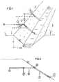
- Fig. 1 shows a drain ditch 1, in which two drain tubes 2 are debouching.
- channels 3 draining at an angle 4 with respect to the longitudinal direction of the ditch, said angle being preferably 90°, but dependent on the shape of the area to be drained said angle may be different.
- the slope of the talus 5 of the ditch is in freshly dug ditches 1:112, which means that the angle 6 between said talus and a horizontal plane is about 33°. In existing water courses or in special cases the angle 6 has another value.
- Fig. 2 shows the complete headwall unit.
- Said headwall unit comprises a tube 8 having at its free end a socket 7 for connecting the drain tube 2 with the tube 8 by means of a click connection.
- the tube 8 is coupled to a gutter-shaped member 9 by means of a coupling head 10.
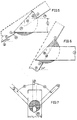
- Fig. 3 shows the talus gutter 9 in a cross-sectional view.
- the gutter has upright edges 11 extending inwardly at an angle of about 80° with respect to the bottom of the gutter, whilst bend-over rims 12 provide additional rigidity.
- ground of the talus is deposited against the upright rims 11, so that a good fixation is ensured, whilst the depth of the gutter is sufficient to accomodate, as shown in Figs. 5 and 6, the coupling head 10, so that with respect to mowing and cleaning of the talus no hindrance occurs.
- Fig. 4 is a front view of the talus gutter 9, which has a circular hole 13, the section of which is slightly smaller than that of the coupling head 10 which has a spherical outer surface.
- Fig. 5 shows a sectional view on the line A-A in Fig. 1 of the coupling head 10 fitting into the hole 13 of the talus gutter 9 at the normal talus slope at an angle 6 of about 33°.
- Fig. 6 shows the same at an angle of 60°.
- Fig. 7 shows that owing to the possibility of lateral pivoting the "setting" of the channel 3 at various angles 4 is possible.
- the outlet construction need not be distorted and the talus gutter 9 can be dug in in a normal manner.
- Fig. 8 is a sectional view of the coupling head 10. As appears from said figure, the centre 16 of the spherical outer surface of said head 10 is located at a given distance 17 above the axis 18 of the bore accomodating tube 8 (Figs. 5 and 6). A further cylindrical part of the head having a height 19 ensures that the pivotability of the head with respect to the gutter has a limitation in all directions.
- the fixed connection between head 10 and tube 8 is obtained by a plurality of tooth-shaped lugs 20 (Fig. 9) having dimensions such, that the head 10 can be manually forced onto the end of tube 8 in the direction C.
Landscapes
- Engineering & Computer Science (AREA)
- Architecture (AREA)
- Civil Engineering (AREA)
- Structural Engineering (AREA)
- Joints Allowing Movement (AREA)
- Road Paving Structures (AREA)
- Rigid Pipes And Flexible Pipes (AREA)
- Sewage (AREA)
Claims (5)
Priority Applications (1)
| Application Number | Priority Date | Filing Date | Title |
|---|---|---|---|
| AT85200943T ATE34193T1 (de) | 1984-08-28 | 1985-06-14 | Auslaufkonstruktion fuer drainagerohre mit die boeschung schuetzenden eigenschaften. |
Applications Claiming Priority (2)
| Application Number | Priority Date | Filing Date | Title |
|---|---|---|---|
| NL8402621A NL8402621A (nl) | 1984-08-28 | 1984-08-28 | Uitmondingsconstructie met taludbeschermende eigenschappen t.b.v. buisleidingen in het algemeen en draineerleidingen in het bijzonder. |
| NL8402621 | 1984-08-28 |
Publications (2)
| Publication Number | Publication Date |
|---|---|
| EP0175396A1 EP0175396A1 (de) | 1986-03-26 |
| EP0175396B1 true EP0175396B1 (de) | 1988-05-11 |
Family
ID=19844378
Family Applications (1)
| Application Number | Title | Priority Date | Filing Date |
|---|---|---|---|
| EP85200943A Expired EP0175396B1 (de) | 1984-08-28 | 1985-06-14 | Auslaufkonstruktion für Drainagerohre mit die Böschung schützenden Eigenschaften |
Country Status (4)
| Country | Link |
|---|---|
| EP (1) | EP0175396B1 (de) |
| AT (1) | ATE34193T1 (de) |
| DE (1) | DE3562641D1 (de) |
| NL (1) | NL8402621A (de) |
Families Citing this family (5)
| Publication number | Priority date | Publication date | Assignee | Title |
|---|---|---|---|---|
| RU2137972C1 (ru) * | 1998-03-19 | 1999-09-20 | Предприятие по добыче, переработке и транспорту газа "Севергазпром" | Водопропускное сооружение под насыпью |
| RU2195596C2 (ru) * | 2000-03-20 | 2002-12-27 | ООО "Баштрансгаз" ОАО "Газпром" | Переход трубопровода через водную преграду |
| NL1036027C (nl) * | 2008-10-07 | 2010-04-14 | Aannemersbedrijf Knipscheer B V | Afwatering. |
| CN102102344B (zh) * | 2011-01-28 | 2013-03-13 | 中铁十七局集团第四工程有限公司 | 组装式波纹管涵洞快速拼装方法 |
| NL2028508B1 (nl) * | 2021-06-22 | 2022-12-29 | Sijbren Bergsma Brugt | Inrichting voor het inbedden van een drainage-uitloop in een walkant |
Family Cites Families (7)
| Publication number | Priority date | Publication date | Assignee | Title |
|---|---|---|---|---|
| NL283993A (de) * | 1900-01-01 | |||
| US1832333A (en) * | 1930-08-13 | 1931-11-17 | Michael L Sullivan | Universal connection between headwall and drainpipe |
| BE794454A (fr) * | 1972-01-24 | 1973-07-24 | Pfeifenbring Bau | Mur ou paroi frontale pour ponceau de cours d'eau |
| CH595581A5 (en) * | 1975-11-19 | 1978-02-15 | Promastic Ag | Plastics pipe to be bonded to concrete socket |
| JPS5375520A (en) * | 1976-12-16 | 1978-07-05 | Kubota Ltd | Universal joint for plastic pipes |
| NL7614163A (en) * | 1976-12-20 | 1978-06-22 | Bleek Walter | Embankment pipe outlet protective securing slab unit - with varying dia. rings inserted from rear into opening cut |
| JPS5441548A (en) * | 1977-08-11 | 1979-04-02 | Robertson Co H H | Head wall unit |
-
1984
- 1984-08-28 NL NL8402621A patent/NL8402621A/nl not_active Application Discontinuation
-
1985
- 1985-06-14 EP EP85200943A patent/EP0175396B1/de not_active Expired
- 1985-06-14 AT AT85200943T patent/ATE34193T1/de not_active IP Right Cessation
- 1985-06-14 DE DE8585200943T patent/DE3562641D1/de not_active Expired
Also Published As
| Publication number | Publication date |
|---|---|
| EP0175396A1 (de) | 1986-03-26 |
| DE3562641D1 (en) | 1988-06-16 |
| NL8402621A (nl) | 1986-03-17 |
| ATE34193T1 (de) | 1988-05-15 |
Similar Documents
| Publication | Publication Date | Title |
|---|---|---|
| US4490067A (en) | Modular drain system | |
| US5568785A (en) | Utility marking device | |
| US5092076A (en) | Planter edging landscaping system | |
| US4702034A (en) | Edging assembly | |
| US4815888A (en) | Swimming pool drain | |
| US5564857A (en) | Slutted drain | |
| US4349989A (en) | Fence guard | |
| US7413382B2 (en) | Coupler for leaching chamber systems | |
| EP0175396B1 (de) | Auslaufkonstruktion für Drainagerohre mit die Böschung schützenden Eigenschaften | |
| US7306402B2 (en) | Landscaping channel liner apparatus | |
| CA2260442A1 (en) | Paver block edging system | |
| US20230220633A1 (en) | Articulating channel | |
| US6202700B1 (en) | Self-flushing pipe | |
| US4865503A (en) | Device for joining together building units | |
| KR102119325B1 (ko) | 데크로드의 지지대 결속용 지주 결속구 | |
| ES2347040T3 (es) | Dispositivo para el soporte o conduccion de lineas en canales. | |
| US6413015B1 (en) | Beaver controlling culvert attachment | |
| JP3100872U (ja) | 管継手 | |
| JP3535663B2 (ja) | 雨水ます | |
| JPH0721672Y2 (ja) | 合成樹脂製u字溝 | |
| KR200445658Y1 (ko) | 무소음 트렌치 커버 | |
| AU613940B2 (en) | Method of constructing a sewer and a sewer duct used for the sewer | |
| JPH0735894Y2 (ja) | 合成樹脂製u字溝 | |
| JPH08284344A (ja) | 竪樋と排水管との接続構造 | |
| GB2220245A (en) | Fin drain jointing system |
Legal Events
| Date | Code | Title | Description |
|---|---|---|---|
| PUAI | Public reference made under article 153(3) epc to a published international application that has entered the european phase |
Free format text: ORIGINAL CODE: 0009012 |
|
| AK | Designated contracting states |
Kind code of ref document: A1 Designated state(s): AT BE CH DE FR GB IT LI LU NL SE |
|
| 17P | Request for examination filed |
Effective date: 19860902 |
|
| 17Q | First examination report despatched |
Effective date: 19870227 |
|
| GRAA | (expected) grant |
Free format text: ORIGINAL CODE: 0009210 |
|
| AK | Designated contracting states |
Kind code of ref document: B1 Designated state(s): AT BE CH DE FR GB IT LI LU NL SE |
|
| PG25 | Lapsed in a contracting state [announced via postgrant information from national office to epo] |
Ref country code: NL Effective date: 19880511 Ref country code: LI Effective date: 19880511 Ref country code: IT Free format text: LAPSE BECAUSE OF FAILURE TO SUBMIT A TRANSLATION OF THE DESCRIPTION OR TO PAY THE FEE WITHIN THE PRESCRIBED TIME-LIMIT;WARNING: LAPSES OF ITALIAN PATENTS WITH EFFECTIVE DATE BEFORE 2007 MAY HAVE OCCURRED AT ANY TIME BEFORE 2007. THE CORRECT EFFECTIVE DATE MAY BE DIFFERENT FROM THE ONE RECORDED. Effective date: 19880511 Ref country code: FR Free format text: THE PATENT HAS BEEN ANNULLED BY A DECISION OF A NATIONAL AUTHORITY Effective date: 19880511 Ref country code: CH Effective date: 19880511 Ref country code: BE Effective date: 19880511 Ref country code: AT Effective date: 19880511 |
|
| REF | Corresponds to: |
Ref document number: 34193 Country of ref document: AT Date of ref document: 19880515 Kind code of ref document: T |
|
| PG25 | Lapsed in a contracting state [announced via postgrant information from national office to epo] |
Ref country code: SE Effective date: 19880531 |
|
| REF | Corresponds to: |
Ref document number: 3562641 Country of ref document: DE Date of ref document: 19880616 |
|
| PG25 | Lapsed in a contracting state [announced via postgrant information from national office to epo] |
Ref country code: LU Free format text: LAPSE BECAUSE OF NON-PAYMENT OF DUE FEES Effective date: 19880630 |
|
| REG | Reference to a national code |
Ref country code: CH Ref legal event code: PL |
|
| EN | Fr: translation not filed | ||
| NLV1 | Nl: lapsed or annulled due to failure to fulfill the requirements of art. 29p and 29m of the patents act | ||
| PG25 | Lapsed in a contracting state [announced via postgrant information from national office to epo] |
Ref country code: DE Effective date: 19890301 |
|
| PLBE | No opposition filed within time limit |
Free format text: ORIGINAL CODE: 0009261 |
|
| STAA | Information on the status of an ep patent application or granted ep patent |
Free format text: STATUS: NO OPPOSITION FILED WITHIN TIME LIMIT |
|
| 26N | No opposition filed | ||
| PG25 | Lapsed in a contracting state [announced via postgrant information from national office to epo] |
Ref country code: GB Effective date: 19890614 |
|
| GBPC | Gb: european patent ceased through non-payment of renewal fee |