EP0174752A2 - Brennkraftmaschine - Google Patents
Brennkraftmaschine Download PDFInfo
- Publication number
- EP0174752A2 EP0174752A2 EP85305842A EP85305842A EP0174752A2 EP 0174752 A2 EP0174752 A2 EP 0174752A2 EP 85305842 A EP85305842 A EP 85305842A EP 85305842 A EP85305842 A EP 85305842A EP 0174752 A2 EP0174752 A2 EP 0174752A2
- Authority
- EP
- European Patent Office
- Prior art keywords
- valve
- piston
- shaft
- engine
- slip
- Prior art date
- Legal status (The legal status is an assumption and is not a legal conclusion. Google has not performed a legal analysis and makes no representation as to the accuracy of the status listed.)
- Withdrawn
Links
Images
Classifications
-
- F—MECHANICAL ENGINEERING; LIGHTING; HEATING; WEAPONS; BLASTING
- F01—MACHINES OR ENGINES IN GENERAL; ENGINE PLANTS IN GENERAL; STEAM ENGINES
- F01L—CYCLICALLY OPERATING VALVES FOR MACHINES OR ENGINES
- F01L7/00—Rotary or oscillatory slide valve-gear or valve arrangements
- F01L7/02—Rotary or oscillatory slide valve-gear or valve arrangements with cylindrical, sleeve, or part-annularly shaped valves
- F01L7/028—Rotary or oscillatory slide valve-gear or valve arrangements with cylindrical, sleeve, or part-annularly shaped valves having the rotational axis coaxial with the cylinder axis and the valve surface not surrounding piston or cylinder
-
- F—MECHANICAL ENGINEERING; LIGHTING; HEATING; WEAPONS; BLASTING
- F02—COMBUSTION ENGINES; HOT-GAS OR COMBUSTION-PRODUCT ENGINE PLANTS
- F02B—INTERNAL-COMBUSTION PISTON ENGINES; COMBUSTION ENGINES IN GENERAL
- F02B1/00—Engines characterised by fuel-air mixture compression
- F02B1/02—Engines characterised by fuel-air mixture compression with positive ignition
- F02B1/04—Engines characterised by fuel-air mixture compression with positive ignition with fuel-air mixture admission into cylinder
-
- F—MECHANICAL ENGINEERING; LIGHTING; HEATING; WEAPONS; BLASTING
- F02—COMBUSTION ENGINES; HOT-GAS OR COMBUSTION-PRODUCT ENGINE PLANTS
- F02B—INTERNAL-COMBUSTION PISTON ENGINES; COMBUSTION ENGINES IN GENERAL
- F02B3/00—Engines characterised by air compression and subsequent fuel addition
- F02B3/06—Engines characterised by air compression and subsequent fuel addition with compression ignition
Definitions
- the invention relates to internal combustion engines fuelled by gasoline, diesel oil etc., and in particular to a rotary valve mechanism and cylinder head assembly therefor.
- Patent Specification US 3,274,901 discloses an internal combustion engine having valves rotatable about an axis perpendicular to the crankshaft.
- the valve was provided with a flange which rotates in the combustion chamber to open and close inlet and exhaust gas passages.
- the valve includes a central sleeve in which a helically grooved rod reciprocates and causes the valve and its flange to oscillate, turning back and forth with each cycle. This presupposes two-cycle operation, and the valve, being located in the combustion chamber, is directly exposed to the full heating and corrosive effects of the exhaust gas.
- US Patent 3,989,025 proposes a rotary valve for each of multiple cylinders constructed of pressed graphite to make them self-lubricating and self-fitting despite the conditions in the combustion chamber.
- a shaft is carried by and extends from the piston through its cylinder and valve, and one-way drive means interconnects the shaft and the valve.
- the drive means preferably comprises a key spiralling about the length of an extension of the shaft, a slip-ring driver having a keyway receiving the key and a step for driving a slip-ring fast with respect to the valve and rotatable with respect to the shaft. More than one opposed spiral may be provided. Two sets of such components may be provided so that the valve is rotated part of a revolution by one set on each successive engine stroke. In a four stroke engine, 90° rotation may be provided, in a two stroke 180° as the said part of a revolution.
- the inlet connection may be adjacent the outlet so that the charge of fuel and air fed may be preheated.
- the piston may be provided with a recess tapered on opposite sides for equalizing the combustion of the fuel on ignition.
- the axis of the shaft should be at least parallel to that of the cylinder, and preferably coincident therewith.
- the arrangement involves comparatively little cylinder head mass, by avoiding the need for any timing gear and/or associated tappet valve parts, and makes for efficient performance by kinetic occlusion of exhaust and intake gases.
- the shaft extending from the piston helps guide, the piston in the cylinder, and makes it possible to keep the depth of the piston head low.
- the shaft may be wedged, keyed or pinned to the piston, and may be of the same material.
- the valve may have passageways into and out of the cylinder of an angular extent for producing a desired degree of intake and dwell. This makes the arrangement self timing.
- the engine is capable of "better breathing", of accommodating variations in fuel quality, and can run quietly, economically, coolly, and cleanly.
- the invention is applicable to engines working on the otto cycle (gasoline or LPG or propane combustion) or Diesel cycle.
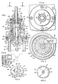
- a cylinder assembly 10 of an IC engine 14 includes a cylinder head assembly 12 having a jacketed cylinder block 16 containing a piston 18. Connected by a wrist pin 20 to the piston 18 is a connecting rod 21, the other end of which is journalled to a crankshaft (not shown).
- the engine 14 may have any number of cylinders.
- a rotary valve 22 is driven by a shaft 24 carried by the piston 18,rotates to control the intake into a combustion chamber 26 of a cylinder 28 of an air-fuel mixture, and the exhaust of combustion gases, as the engine goes through its working cycle.
- the valve 22 rotates about an axis coincident with that of the cylinder 28.
- the valve rotation axis is perpendicular to the axis of rotation of the crankshaft.
- the cylinder block 16 is provided with coolant passages 30 surrounding the cylinder 28 and communicating with corresponding coolant passages 32 in a cylinder head 34 of the head assembly 12, which is fixed to the block 16 by head bolts 36.
- the head assembly 12 includes an upstanding housing 38 for the valve22, defining an internal cylindrical bore 40 in which the valve 22 may rotate.
- the housing 38 is shown with coolant passages 42 communicating with the head passages 32.
- Circumferential cooling fins 44 are spaced along a major portion of the length of housing 38.
- valve 22 Extending laterally from the housing 38 are intake and exhaust manifold connections 46,48 one above the other.
- the valve 22 rotates to permit communication in sequence between each of these connections and the combustion chamber 26.
- the valve 22 is provided with radial recesses 50, 51 in the shape of arc sectors of about 50°.
- the recess 50 provides communication between the intake connection 46 and a port 52 opening through the cylinder into the combustion chamber 26.
- the recess 51 is brought into registry ( Figure 6) with the exhaust connection 48 and with the port 52 opening into the combustion chamber 26.
- the recesses 50,51 are of different arcuate lengths and separated by 90° for movement in succession into registry with the single port 52.
- the recesses 50,51 provide 2-5° of advance or delayed intake and exhaust overlap.
- the cylinder head 34 is also provided with a threaded bore 56 for a spark plug 57.
- a lower end face 58 of the valve 22 is brought into immediate, parallel adjacency to the cylinder head 34 just above the combustion chamber 26, and permits the selection of a timing relationship for intake and exhaust cycles which will make possible the use of fuel of minimum octane.
- Sealing between the valve 22 and bore 40 is provided by an O-ring 60, above which a substantial solid portion of' the valve 22 provides for transfer of the heat generated for extraction by the coolant in the passages 42 and by the fins 44. Thus, there is a marked resistance to the erosion caused by high operating temperatures.
- the shaft 24 reciprocates centrally within the valve 22.
- the valve 22 has a central, axial bore 62 for that purpose, and an O-ring 64 at the lower end of the bore 62 provides sealing about the periphery of the shaft 24.
- the bore 40 of the housing 38 and the lower valve face 58 may be coated with molybdenum disulphide, and/or lubricating oil under pressure may be supplied by passages (not shown) to the housing 38.
- annular recesses 54 are spaced along the valve member 22; they are in effect equally spaced rings, and stop short of the region of the valve 22 which contains the intake and exhaust passages 50,51. In Figure 3, it can be seen there are arcuate sectors containing the intake and exhaust passages 50,51, in which two sectors the annular recesses 54 are not provided.
- valve 22 This permits the greatest possible use of the radius for the intake and exhaust passages, and enhances thermal transfer between the valve 22 and its housing 38 in the sectors which contain the intake and exhaust passages 50,51.
- a series of recesses 55 there are provided in the lower surface 58 of the valve 22 a series of recesses 55, not concentric with the axis of rotation of the valve 22, but eccentric or oval. This provides a sweeping action as the valve 22 rotates for removing carbon pieces and other matter from the floor of the cavity in which valve 22 rotates so that they are burned and ultimately be discharged in the exhaust stream.
- the recesses 55 terminate short of the intake and exhaust passages 50,51. They reduce friction and assist in heat transfer.
- the valve 22 can be formed by casting and then provided with a laminated coating, for example of molybdenum disulphide to provide a smooth, low friction surface inspite of any underlying casting irregularities.
- a slip-ring assembly 66 at the upper end of the housing 38 includes washer-like slip--ring drivers 68 (upper) and 68' (lower) for driving corresponding upper and lower slip-rings 70,70' rotationally in response to reciprocation of the shaft 24.
- the shaft 24 carries a reduced diameter extension 72 at the upper end with keys 74 spiralling about its length, each circumscribing an arc of approximately 90° for sliding interengagement with the slip ring drivers 68,68'.
- These drivers have an annular body 76 and a flange 78 of slightly greater diameter with a sawtooth driving surface 80 forming four ramp surfaces 82 separated by steps 84.
- a central bore 86 has a close tolerance sliding engagement with the shaft extension 72.
- Opening on one side of the bore 86 is a keyway 88 for slidable engagement with one of the keys 74.
- the driver 68 is turned through an arcuate angular sector of substantially 90° with each full extension or retraction of the extension 72.
- the keyway 88 is a slot 90 of approximately 90° arcuate extent for receiving the opposite key 74.
- the slip-rings 70,70' are of the same general configuration as the drivers 68,68' but have a central bore of sufficient diameter not to engage either of the keys 74. They are rotated by the drivers 68,68' as they rotate on reciprocation of the shaft extension 72.
- a spiral compression spring 92 has a relatively light spring constant but urges the drivers 68,68' apart and into engagement with the corresponding slip-rings 70,70'. Movement of the shaft extension 72 in either direction will by the frictional engagement lift one of the drivers 68,68' away from its corresponding slip-ring. If the extension 72 is driven up, the driver 68' will be lifted from its slip-ring 70', while the driver 68 will remain in firm driving engagement with its slip-ring 70.
- the resulting rotation of the slip-ring 70 follows the key 74 in the keyway 88. If the extension 72 moves downward with the piston 18, the driver 68 is carried by frictional engagement away from extension 72, and out of engagement with the slip-ring 70, while the driver 68' rotates its slip-ring 70'.
- Each of the slip-rings 70,70' is driven in the same direction of rotation about the longitudinal axis of extension 72 by reciprocating movement of the piston 18.
- the valve 22 is rotated by the slip-rings 70,70' through a sleeve 22'; which is an integral extension of the valve 22.
- the sleeve 22' is secured to the slip-ring 70' by radially spaced pins 96 and to the slip-ring 70' by similar bolts 98 threaded into a laterally projecting collar 94.
- the housing 38 has at its upper end an enlarged diameter portion 100 for receiving the collar 94.
- a retainer ring 102 is fitted above the portion 100 and threaded thereto by screws 104 to retain the collar 94 and valve 22 in the housing 38.
- a detent pin assembly 101 includes a spring-loaded ball or tip t fitting into one of the corresponding recesses of the valve 22, there being four such recesses spaced at 90° about the valve 22, for ensuring that the valve is driven in precise steps.
- a guard 106 above the housing 38 is of thin metal or synthetic material to provide a shroud for projecting the shaft extension 72.
- the guard 106 is only partially illustrated in Figure 1, being broken away for illustrative purposes, but is of sufficient height to enclose the extension 72 when the piston 18 is at its top dead centre position.
- the extension 72 is fitted to shaft 24 by being threaded as at 108, and the shaft 24 may be threaded into a corresponding bore 110 in piston 18.
- lateral bores 112 extend across the upper end of the valve 22 opening from opposite sides of the housing 38 for pins for locking the extension 72 for removal on disassembly, or replacement.
- Exhaust gases are driven from the chamber 26 as the piston 18 moves towards its top dead centre position once more.
- the spark initiates the ignition, and burning of the compressed and heated mixture in the chamber 26 preferably occurs while the piston is still rising to the end of its compression stroke.
- Equal ignition provided by shaping piston 18 with a crown which provides the chamber 26 with a hollowed configuration for allowing the combustion mixture to undergo a gradual compression as the piston approaches top dead centre.
- the piston 18 is provided with a recess 114 providing an arcuate portion 116 of the piston crown which is flat but tapering at 10° uniformally from opposite sides to a deepest point 118 opposite and located below the spark plug 57 in its bore 56.
- the recess 114 allows the mixture to be directed towards the spark plug 57, and results in ignition such that the fuel mixture is fed into the advancing flame front and causes fuel to be completely burned.
- additional space is provided in the region of the spark plug 57 for a build-up of heat in the charge of mixture in the chamber 26. This causes the flame front to be advanced smoothly around both sides of shaft 24, and smooth, detonation-free combustion. This build-up of heat should not be permitted to abate or cool too quickly, lest the mixture does not burn fully causing fuel exhaust pollution.
- the recess 114 being tapered on opposite sides of the flat portion 116 and towards the spark plug 57, there is produced a sudden squeeze in the space occupied by the fuel and air mixture as the piston 18 rises toward the cylinder head.
- the mixture is compressed out of a region 120, over the flat portion 116, and into the remaining combustion space of the chamber 26. This increases turbulence, and forces the mixture towards the flame front for better combustion.
- the tapering recess 114 allows the compression to be gradual before the piston 18 reaches top dead centre.
- the resultant smooth advance of the mixture reduces the formation of oxides of nitrogen and consequent pollution. No gases are trapped behind shaft 24.
- the configuration of the piston 18 and cylinder 28 produces a combustion efficiency which is very near 1.0.
- the location of the intake connection 46 above the exhaust connection 48 causes the intake mixture to be warmed as it enters the cylinder. This preheating is advantageous.
- the shaft 24 results in the piston 18 being stably oriented and reduces the need for a deep skirt.
- the piston may be machined perfectly circular which is important from an economic and manufacturing viewpoint.
- the valve configuration eliminates the need for such cavities and other irregularities in the combustion chamber 26. A smooth gas flow is thus achieved during the firing cycle and utilized for preventing formation of nitrogen oxides.
Landscapes
- Engineering & Computer Science (AREA)
- Mechanical Engineering (AREA)
- General Engineering & Computer Science (AREA)
- Valve-Gear Or Valve Arrangements (AREA)
- Cylinder Crankcases Of Internal Combustion Engines (AREA)
- Taps Or Cocks (AREA)
- Multiple-Way Valves (AREA)
- Valve Device For Special Equipments (AREA)
Applications Claiming Priority (2)
| Application Number | Priority Date | Filing Date | Title |
|---|---|---|---|
| US06/649,699 US4592312A (en) | 1984-09-12 | 1984-09-12 | High efficiency performance kinetic occlude system with rotary valve |
| US649699 | 1984-09-12 |
Publications (2)
| Publication Number | Publication Date |
|---|---|
| EP0174752A2 true EP0174752A2 (de) | 1986-03-19 |
| EP0174752A3 EP0174752A3 (de) | 1987-02-04 |
Family
ID=24605881
Family Applications (1)
| Application Number | Title | Priority Date | Filing Date |
|---|---|---|---|
| EP85305842A Withdrawn EP0174752A3 (de) | 1984-09-12 | 1985-08-16 | Brennkraftmaschine |
Country Status (3)
| Country | Link |
|---|---|
| US (1) | US4592312A (de) |
| EP (1) | EP0174752A3 (de) |
| JP (1) | JPS6172811A (de) |
Cited By (1)
| Publication number | Priority date | Publication date | Assignee | Title |
|---|---|---|---|---|
| US9458315B2 (en) | 2009-08-25 | 2016-10-04 | Sabic Global Technologies B.V. | Flame retardant thermoplastic polycarbonate compositions and films made therefrom |
Families Citing this family (3)
| Publication number | Priority date | Publication date | Assignee | Title |
|---|---|---|---|---|
| US5967108A (en) * | 1996-09-11 | 1999-10-19 | Kutlucinar; Iskender | Rotary valve system |
| US20060102130A1 (en) * | 2004-11-18 | 2006-05-18 | Bachelier Leon D | Rotary valve |
| RU2373404C2 (ru) * | 2007-11-16 | 2009-11-20 | Олег Станиславович Гладкевич | Механизм газораспределения двигателей внутреннего сгорания |
Family Cites Families (20)
| Publication number | Priority date | Publication date | Assignee | Title |
|---|---|---|---|---|
| GB597729A (en) * | 1945-08-24 | 1948-02-02 | Alfred Charles Morrison | Improvements in or relating to combustion chambers of internal combustion engines |
| FR480321A (de) * | 1900-01-01 | |||
| US821227A (en) * | 1905-05-11 | 1906-05-22 | Thaddious V Elliott | Oscillating valve for steam-engines. |
| FR422804A (fr) * | 1910-11-19 | 1911-03-31 | Constant Francois Marie Galain | Moteur à explosions sans soupapes |
| FR13863E (fr) * | 1910-11-19 | 1911-07-25 | Constant Francois Marie Galain | Moteur à explosions sans soupapes |
| US1010754A (en) * | 1911-03-14 | 1911-12-05 | Allen E Hall | Internal-combustion engine. |
| FR468311A (fr) * | 1913-02-10 | 1914-07-03 | Fernand Bastet | Distributeur automatique rotatif pour moteur sans soupapes |
| US1177698A (en) * | 1914-04-28 | 1916-04-04 | John Good | Internal-combustion engine. |
| US1232849A (en) * | 1916-05-16 | 1917-07-10 | Leon L Russell | Valve. |
| US1359669A (en) * | 1918-03-13 | 1920-11-23 | Continental Engineering Corp | Valve-rotator for internal-combustion engines |
| GB151142A (en) * | 1919-08-06 | 1920-09-23 | Cyril Prescott Schulz | Improvement in the valve mechanism of internal combustion engines |
| US1361978A (en) * | 1920-03-08 | 1920-12-14 | George John William | Internal-combustion engine |
| US1580720A (en) * | 1922-07-31 | 1926-04-13 | John K Gold | Two-cycle engine |
| US1777464A (en) * | 1929-08-10 | 1930-10-07 | Addison Invest Company | Rotary-valve mechanism |
| US1924188A (en) * | 1929-10-10 | 1933-08-29 | Malcolm S Losey | Rotary valve for internal combustion engines |
| US1974454A (en) * | 1932-02-08 | 1934-09-25 | Louis P Gamache | Oscillating valve |
| US3274901A (en) * | 1964-09-28 | 1966-09-27 | Oscar A Yost | Oscillating port valve |
| US3989025A (en) * | 1975-02-18 | 1976-11-02 | Daniel Franco | Rotary valve |
| JPS5838610B2 (ja) * | 1979-03-05 | 1983-08-24 | トヨタ自動車株式会社 | 内燃機関 |
| DE3137738C1 (de) * | 1981-09-23 | 1983-06-01 | Dr.Ing.H.C. F. Porsche Ag, 7000 Stuttgart | Brennkraftmaschine mit Fremdzuendung |
-
1984
- 1984-09-12 US US06/649,699 patent/US4592312A/en not_active Expired - Fee Related
-
1985
- 1985-08-16 EP EP85305842A patent/EP0174752A3/de not_active Withdrawn
- 1985-09-12 JP JP60202509A patent/JPS6172811A/ja active Pending
Cited By (1)
| Publication number | Priority date | Publication date | Assignee | Title |
|---|---|---|---|---|
| US9458315B2 (en) | 2009-08-25 | 2016-10-04 | Sabic Global Technologies B.V. | Flame retardant thermoplastic polycarbonate compositions and films made therefrom |
Also Published As
| Publication number | Publication date |
|---|---|
| US4592312A (en) | 1986-06-03 |
| JPS6172811A (ja) | 1986-04-14 |
| EP0174752A3 (de) | 1987-02-04 |
Similar Documents
| Publication | Publication Date | Title |
|---|---|---|
| US4467752A (en) | Internal combustion engine | |
| US5868112A (en) | Deep angle injection nozzle and piston having complementary combustion bowl | |
| US5152259A (en) | Cylinder head for internal combustion engine | |
| JPH05503129A (ja) | 内燃機関 | |
| US4934344A (en) | Modified four stroke cycle and mechanism | |
| US5816201A (en) | Offset crankshaft mechanism for an internal combustion engine | |
| HU219044B (hu) | Axiáldugattyús forgógép | |
| US20210293178A1 (en) | Internal Combustion Engine with Adaptable Piston Stroke | |
| KR20200015472A (ko) | 압축 착화 엔진의 개선된 시스템 및 방법 | |
| EP0293335A2 (de) | Steuerungsvorrichtung für Hubkolbenmaschinen, wie endothermische Hubmaschinen, mit einem Drehventil in Form eines Drehkörpers, insbesondere einer Kugel | |
| US5228294A (en) | Rotary internal combustion engine | |
| EP0604223A1 (de) | Kolbenskopf fur Dieselmotor | |
| EP0174752A2 (de) | Brennkraftmaschine | |
| US4800853A (en) | Adiabatic internal combustion engine | |
| US5072705A (en) | Rotary engine and method | |
| CN101096930A (zh) | 旋转气缸阀发动机 | |
| US4867117A (en) | Rotary valve with integrated combustion chamber | |
| US4401062A (en) | Rotary piston engine | |
| US4974553A (en) | Rotary internal combustion engine | |
| US7121247B2 (en) | Spherical rotary engine valve assembly | |
| US5161378A (en) | Rotary internal combustion engine | |
| US4682572A (en) | High efficiency performance kinetic occlude system with rotary valve | |
| AU633032B2 (en) | Rotary internal combustion engine | |
| EP1282764B1 (de) | Zweitaktbrennkraftmaschine mit vergrössertem wirkungsgrad und niedrigem giftgasausstoss | |
| US6478006B1 (en) | Working cycle for a heat engine, especially an internal combustion engine, and an internal combustion engine |
Legal Events
| Date | Code | Title | Description |
|---|---|---|---|
| PUAI | Public reference made under article 153(3) epc to a published international application that has entered the european phase |
Free format text: ORIGINAL CODE: 0009012 |
|
| AK | Designated contracting states |
Kind code of ref document: A2 Designated state(s): DE FR GB IT SE |
|
| PUAL | Search report despatched |
Free format text: ORIGINAL CODE: 0009013 |
|
| AK | Designated contracting states |
Kind code of ref document: A3 Designated state(s): DE FR GB IT SE |
|
| 17P | Request for examination filed |
Effective date: 19870722 |
|
| 17Q | First examination report despatched |
Effective date: 19871228 |
|
| STAA | Information on the status of an ep patent application or granted ep patent |
Free format text: STATUS: THE APPLICATION HAS BEEN WITHDRAWN |
|
| 18W | Application withdrawn |
Withdrawal date: 19880611 |