EP0174631B1 - Method and apparatus for forming warp beam of uniform diameter - Google Patents
Method and apparatus for forming warp beam of uniform diameter Download PDFInfo
- Publication number
- EP0174631B1 EP0174631B1 EP85111402A EP85111402A EP0174631B1 EP 0174631 B1 EP0174631 B1 EP 0174631B1 EP 85111402 A EP85111402 A EP 85111402A EP 85111402 A EP85111402 A EP 85111402A EP 0174631 B1 EP0174631 B1 EP 0174631B1
- Authority
- EP
- European Patent Office
- Prior art keywords
- warp
- winding tension
- reed
- warps
- middle portion
- Prior art date
- Legal status (The legal status is an assumption and is not a legal conclusion. Google has not performed a legal analysis and makes no representation as to the accuracy of the status listed.)
- Expired
Links
- 238000000034 method Methods 0.000 title claims description 16
- 238000004804 winding Methods 0.000 claims description 32
- 235000014676 Phragmites communis Nutrition 0.000 claims description 19
- 238000012545 processing Methods 0.000 claims description 3
- 238000009940 knitting Methods 0.000 description 3
- 238000011144 upstream manufacturing Methods 0.000 description 3
- 230000003247 decreasing effect Effects 0.000 description 2
- 238000012544 monitoring process Methods 0.000 description 2
- 238000006243 chemical reaction Methods 0.000 description 1
- 230000001276 controlling effect Effects 0.000 description 1
- 238000010586 diagram Methods 0.000 description 1
- 239000004744 fabric Substances 0.000 description 1
- 238000007689 inspection Methods 0.000 description 1
- 230000001788 irregular Effects 0.000 description 1
- 238000005259 measurement Methods 0.000 description 1
- 239000000843 powder Substances 0.000 description 1
- 230000001105 regulatory effect Effects 0.000 description 1
- 238000012360 testing method Methods 0.000 description 1
- 239000002759 woven fabric Substances 0.000 description 1
Images
Classifications
-
- D—TEXTILES; PAPER
- D02—YARNS; MECHANICAL FINISHING OF YARNS OR ROPES; WARPING OR BEAMING
- D02H—WARPING, BEAMING OR LEASING
- D02H5/00—Beaming machines
Definitions
- the present invention relates to warp beaming for a warp knitting machine or a loom, especially to a method and an apparatus for forming a warp beam of uniform diameter, even in a salvedge portion while controlling winding tension of a warp.
- a predetermined number of warp beams are fixedly held on one common shaft to form an integrated single warp beam.
- a sheet consisting of a plurality of parallel warps is withdrawn therefrom by rotation of the shaft for a knitting operation. If the warp beams are different in diameter (below, "inter-beam diameter difference") or if a single beam is different in diameter (below, "intra-beam diameter difference”), the tension of the warp in the sheet tends to vary along the width of the sheet. The difference of the tension causes a wale streak in the resultant fabric.
- a similar drawback occurs in a loom for producing a woven fabric. Therefore, it has been desired for a long time to provide a method and apparatus for obtaining warp beams of a uniform diameter even in a selvedge portion.
- the local diameter of the beam i.e., a diameter of the beam at a certain widthwise position
- the distance between the flanges 32 increases the further out from the barrrel.
- local diameters of various portions of the beam on the warper are frequently inspected during the winding operation by stopping the machine. If there is a certain difference between measured diameters, a width and/or a position of reed is adjusted to compensate for distribution of the warp on the beam. It is apparent that this method is very cumbersome and lowers productivity.
- a correlation coefficient is calculated from an accumulated warp length already wound on a beam and accumulated revolutions of the beam corresponding thereto and is compared to a predetermined reference correlation coefficient, whereby the total winding tension is controlled to compensate for the beam diameter.
- a correlation coefficient is calculated from a rotational rate of a warp beam and a winding speed of warp and is compared to a predetermined reference correlation coefficient, whereby the total winding tension is controlled to compensate for the beam diameter.
- the objects of the present invention are achievable by a method for forming a warp beam of uniform diameter in a warper, while guiding warps by a reed, including the steps of:
- the local winding tension is preferably measured at a middle portion of the warp sheet besides the opposite side portions.
- the intra-beam diameter difference on the beam is judged by using, as a reference, a value obtained from the middle portion.
- the abovesaid method preferably further includes a step of avoiding damage of the warp due to an excessive winding tension in the upstream region.
- the local winding tension of the middle portion warp may be controlled to follow a predetermined time schedule pattern by referring to the control signal.
- the abovesaid method according to the present invention is preferably carried out by a device for forming a warp beam of uniform diameter in a warper, while guiding warps by a reed, including means for measuring a local winding tension at a plurality of widthwise portions of a warp sheet to be wound on the warp beam, including opposite side portions thereof; means for processing the measured values of the local winding tension and generating a control signal for adjusting a width and/or a position of the reed; and means for adjusting the reed in accordance with the control signal.
- the abovesaid device may further include means for adjusting a local winding tension of the middle portion warps, means for adjusting a winding speed of the warps and means for memorizing a time schedule of a predetermined winding tension to be fed to the processing means.
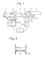
- Fig. 1 Main parts of a device according to a first embodiment are shown in Fig. 1, in which warps Y are fed in a sheet form from the right and wound on a positively driven warp beam 1. Midway of the passage, the warps Y pass through a front roller 41 and a measuring roller 42; a group of sensors 51, 52, 53, each provided at one side portion, a middle portion, and the other side portion of the width of the warp sheet for detecting a local winding tension, i.e., a tension of a yarn at a given widthwise position; a middle reed 3; and a front reed 21.
- the sensor group constitutes a local tension measuring part 5 together with an analog to digital (A/D) converter 54.
- the front reed 21 constitutes a reed adjusting part 2 in combination with motors 22, 23 and an A/D converter 24.
- the front reed 21 is adjustable in its widthwise position and its width by means of the motors 22 and
- the local tensions measured by the sensors 51, 52, and 53 are converted through the A/D converter 54 to digital signals and input to a processor 7, in which the signals are compared to each other and whereby the degree of the intra-beam diameter difference on the beam now being formed is judged. From the result, if control of the beam diameter is required, a signal is output from the processor 7 for driving the motors 22 and 23 to adjust the position and width of the front reed 21 for compensating for the widthwise irregularity of beam diameter.
- a rotational speed of the warp beam 1 is controlled to be a constant value by comparing a voltage V1 preliminarily set in a yarn speed setter 81 and a voltage V2 output from a tacho generator 43 for detecting a yarn speed connected to the measuring roller 42 and
- An excessive winding tension monitoring part 6 is provided upstream of the front roller 41 for detecting a winding tension of the warps Y between a creel of a warp source (not shown) and the front roller 41 including a sensor 61 and an A/D converter 62 for receiving a signal from the former and transmitting it to the processor 7 while converting the signal to a digital form.
- a tension regulating part 4 is provided in the vicinity of the front roller 41 and the measuring roller 42 just downstream of the tension measuring part 6, wherein an electromagnetic brake 45 of a powder type for braking the front roller 41 to increase warp tension between the beam 1 and the front roller 41, a motor 44 for positively driving the measuring roller 42 to decrease warp tension between the beam 1 and the front roller 41, and a counter 46 for measuring the number of revolutions of the measuring roller 42 are provided.
- the rotational speed of the motor 44 is decreased to some extent or, in an extreme case, to zero, so that damage of the warps can be avoided.
- the preset voltage in the yarn speed setter 81 is changed so that the rotational rate of the beam is decreased.
- the local winding tension of the middle portion warp detected by the sensor 52 (hereinafter referring to "reference tension") is compared, in the processor 7, with a corresponding value on a tension pattern relative to the time passage preset in the storage 10 by taking an accumulated number of revolutions of the measuring roller 42 into account. If there is any difference therebetween, signals are generated from the processor 7 to the electromagnetic brake 45 and the motor 44 as well as the yarn speed setter 81 through lines C1, C2, and C3, respectively, so that the reference winding tension is matched with the preset tension pattern.
- warp beams having identical diameters are always obtained, whereby the inter-beam dia- . meter difference is eliminated.
- the intra-beam diameter difference is also avoidable by the provision of the local tension measuring part 5 and the reed adjusting part 2, as described before in relation to Fig. 1.
- 600 ends of 100 denier diacetate filament yarns were wound to form a warp beam at a rate of 600 m/min by utilizing a warper provided with the device of Fig. 1 according to the present invention.
- Tension meters having a detecting range of from 0 to 50 gr were adopted as the sensors 51, 52, and 53, engaged with the leftmost warp, the 300th warp, and the rightmost warp, respectively.
- the measured values were output therefrom as voltages in a range from 5 to 20 mV to the converter 54, for conversion to a digital value, then input to the processor 7.
- Measurement was carried out sequentially ten times per second in each sensor, and the moving average of the ten data was adopted as the measured tension by taking the possible tension variance caused by eccentricity of the beam into account.
Landscapes
- Engineering & Computer Science (AREA)
- Textile Engineering (AREA)
- Warping, Beaming, Or Leasing (AREA)
- Looms (AREA)
Description
- The present invention relates to warp beaming for a warp knitting machine or a loom, especially to a method and an apparatus for forming a warp beam of uniform diameter, even in a salvedge portion while controlling winding tension of a warp.
- In a conventional warp knitting machine, a predetermined number of warp beams are fixedly held on one common shaft to form an integrated single warp beam. A sheet consisting of a plurality of parallel warps is withdrawn therefrom by rotation of the shaft for a knitting operation. If the warp beams are different in diameter (below, "inter-beam diameter difference") or if a single beam is different in diameter (below, "intra-beam diameter difference"), the tension of the warp in the sheet tends to vary along the width of the sheet. The difference of the tension causes a wale streak in the resultant fabric. A similar drawback occurs in a loom for producing a woven fabric. Therefore, it has been desired for a long time to provide a method and apparatus for obtaining warp beams of a uniform diameter even in a selvedge portion.
- Especially, since a
barrel 31 on which the beam is formed has taperedflanges 32 at opposite ends thereof, as shown in Fig. 3, the local diameter of the beam (i.e., a diameter of the beam at a certain widthwise position) at the selvedge portions tends to be irregular relative to the middle portion of the beam, because the distance between theflanges 32 increases the further out from the barrrel. In the prior art, to avoid this intra-beam diameter difference, local diameters of various portions of the beam on the warper are frequently inspected during the winding operation by stopping the machine. If there is a certain difference between measured diameters, a width and/or a position of reed is adjusted to compensate for distribution of the warp on the beam. It is apparent that this method is very cumbersome and lowers productivity. - In Japanese Examined Patent Publication (Kokoku) No. 56-34661, to avoid inter-beam diameter difference, a correlation coefficient is calculated from an accumulated warp length already wound on a beam and accumulated revolutions of the beam corresponding thereto and is compared to a predetermined reference correlation coefficient, whereby the total winding tension is controlled to compensate for the beam diameter. Also in Japanese- Examined Patent Publication (Kokoku) No. 56-34662, a correlation coefficient is calculated from a rotational rate of a warp beam and a winding speed of warp and is compared to a predetermined reference correlation coefficient, whereby the total winding tension is controlled to compensate for the beam diameter. These methods, however, are effective only for inter-beam diameter differences and cannot improve the intra-beam diameter difference.
- It may be possible, in principle, to carry out inspection of the local diameter of the selvedge portion of the beam directly by an image sensor or a video sensor. This technique, however, is not . reliable yet and, even if it becomes so in the future, the cost could be too high for practical use.
- Thus, it is an object of the present invention to improve the intra- and/or inter-beam diameter difference based on a principle that the winding tension of the warp varies corresponding to the beam diameter.
- It is another object of the present invention to provide a method and a device for achieving a uniform intra- and/or inter-beam diameter of warp beams by utilizing the abovesaid correspondence of winding tension and beam diameter. The objects of the present invention are achievable by a method for forming a warp beam of uniform diameter in a warper, while guiding warps by a reed, including the steps of:
- continuously measuring a local winding tension of warps at a plurality of portions of a warp sheet to be wound on the warp beam, including opposite side portions thereof;
- judging whether there is an intra-beam diameter difference from the measured local tension values and, if existing, generating a control signal; and
- automatically adjusting a position and/or a . width of the reed in accordance with the control signal to improve the warp distribution on the beam and compensate for the intra-beam diameter difference on the beam.
- The local winding tension is preferably measured at a middle portion of the warp sheet besides the opposite side portions. The intra-beam diameter difference on the beam is judged by using, as a reference, a value obtained from the middle portion.
- The abovesaid method preferably further includes a step of avoiding damage of the warp due to an excessive winding tension in the upstream region.
- Further, the local winding tension of the middle portion warp may be controlled to follow a predetermined time schedule pattern by referring to the control signal.
- The abovesaid method according to the present invention is preferably carried out by a device for forming a warp beam of uniform diameter in a warper, while guiding warps by a reed, including means for measuring a local winding tension at a plurality of widthwise portions of a warp sheet to be wound on the warp beam, including opposite side portions thereof; means for processing the measured values of the local winding tension and generating a control signal for adjusting a width and/or a position of the reed; and means for adjusting the reed in accordance with the control signal.
- The abovesaid device may further include means for adjusting a local winding tension of the middle portion warps, means for adjusting a winding speed of the warps and means for memorizing a time schedule of a predetermined winding tension to be fed to the processing means.
- Other objects and advantages of the present invention will be apparent from the following description with reference to the drawings, illustrating preferable embodiments of the present invention, wherein
- Fig. 1 is a diagrammatic perspective view of a first embodiment of a device according to the present invention;
- Fig. 2 is a block diagram of a second embodiment of a device according to the present invention; and
- Fig. 3 is a side view of a barrel of a warp beam, illustrating a tapered flange portion thereof.
- Main parts of a device according to a first embodiment are shown in Fig. 1, in which warps Y are fed in a sheet form from the right and wound on a positively driven warp beam 1. Midway of the passage, the warps Y pass through a
front roller 41 and ameasuring roller 42; a group ofsensors middle reed 3; and afront reed 21. The sensor group constitutes a localtension measuring part 5 together with an analog to digital (A/D)converter 54. Thefront reed 21 constitutes areed adjusting part 2 in combination withmotors D converter 24. Thefront reed 21 is adjustable in its widthwise position and its width by means of themotors - The local tensions measured by the
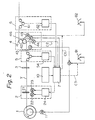
sensors D converter 54 to digital signals and input to aprocessor 7, in which the signals are compared to each other and whereby the degree of the intra-beam diameter difference on the beam now being formed is judged. From the result, if control of the beam diameter is required, a signal is output from theprocessor 7 for driving themotors front reed 21 for compensating for the widthwise irregularity of beam diameter. - In a second embodiment of a device according to the present invention shown in Fig. 2, further parts are added for achieving a more improved compensation of diameter difference of the beam, especially the inter-beam diameter difference. In Fig. 2, the rotational speed of the warp beam 1 is controlled to be a constant value by comparing a voltage V1 preliminarily set in a
yarn speed setter 81 and a voltage V2 output from atacho generator 43 for detecting a yarn speed connected to themeasuring roller 42 and - by adjusting a voltage to be fed to a beam driving DC motor 11 so that a difference between the voltages V1 and V2 is eliminated.
- An excessive winding
tension monitoring part 6 is provided upstream of thefront roller 41 for detecting a winding tension of the warps Y between a creel of a warp source (not shown) and thefront roller 41 including asensor 61 and an A/D converter 62 for receiving a signal from the former and transmitting it to theprocessor 7 while converting the signal to a digital form. A tension regulating part 4 is provided in the vicinity of thefront roller 41 and themeasuring roller 42 just downstream of thetension measuring part 6, wherein anelectromagnetic brake 45 of a powder type for braking thefront roller 41 to increase warp tension between the beam 1 and thefront roller 41, amotor 44 for positively driving themeasuring roller 42 to decrease warp tension between the beam 1 and thefront roller 41, and acounter 46 for measuring the number of revolutions of themeasuring roller 42 are provided. - According to the above arrangement, if the upstream winding tension exceeding a value preset in a
storage 10 is detected by thetension monitoring part 6, the rotational speed of themotor 44 is decreased to some extent or, in an extreme case, to zero, so that damage of the warps can be avoided. In addition, the preset voltage in theyarn speed setter 81 is changed so that the rotational rate of the beam is decreased. - On the other hand, the local winding tension of the middle portion warp detected by the sensor 52 (hereinafter referring to "reference tension") is compared, in the
processor 7, with a corresponding value on a tension pattern relative to the time passage preset in thestorage 10 by taking an accumulated number of revolutions of themeasuring roller 42 into account. If there is any difference therebetween, signals are generated from theprocessor 7 to theelectromagnetic brake 45 and themotor 44 as well as the yarn speed setter 81 through lines C1, C2, and C3, respectively, so that the reference winding tension is matched with the preset tension pattern. Thus, warp beams having identical diameters are always obtained, whereby the inter-beam dia- . meter difference is eliminated. Of course, the intra-beam diameter difference is also avoidable by the provision of the localtension measuring part 5 and thereed adjusting part 2, as described before in relation to Fig. 1. - 600 ends of 100 denier diacetate filament yarns were wound to form a warp beam at a rate of 600 m/min by utilizing a warper provided with the device of Fig. 1 according to the present invention. Tension meters having a detecting range of from 0 to 50 gr were adopted as the
sensors converter 54, for conversion to a digital value, then input to theprocessor 7. - Measurement was carried out sequentially ten times per second in each sensor, and the moving average of the ten data was adopted as the measured tension by taking the possible tension variance caused by eccentricity of the beam into account.
- In a preliminary test, when a diameter of the selvedge portion was 2 mm larger than that of the middle portion, the tension difference between the
sensors 52 and one of 51 and 53 was 12 gr. On the contrary, when a diameter of the selvedge portion was 2 mm smaller than that of the middle portion, the tension difference was -5 gr. By reed control in accordance with a control limit of from -3 gr to 10 gr, the intra-beam diameter difference was suppressed to within 2 mm.
Claims (8)
Applications Claiming Priority (2)
| Application Number | Priority Date | Filing Date | Title |
|---|---|---|---|
| JP189095/84 | 1984-09-10 | ||
| JP59189095A JPS6170038A (en) | 1984-09-10 | 1984-09-10 | Automatic wind-up method and apparatus of warper |
Publications (3)
| Publication Number | Publication Date |
|---|---|
| EP0174631A2 EP0174631A2 (en) | 1986-03-19 |
| EP0174631A3 EP0174631A3 (en) | 1986-08-06 |
| EP0174631B1 true EP0174631B1 (en) | 1988-07-27 |
Family
ID=16235254
Family Applications (1)
| Application Number | Title | Priority Date | Filing Date |
|---|---|---|---|
| EP85111402A Expired EP0174631B1 (en) | 1984-09-10 | 1985-09-09 | Method and apparatus for forming warp beam of uniform diameter |
Country Status (5)
| Country | Link |
|---|---|
| US (1) | US4670953A (en) |
| EP (1) | EP0174631B1 (en) |
| JP (1) | JPS6170038A (en) |
| KR (1) | KR920009245B1 (en) |
| DE (1) | DE3563991D1 (en) |
Cited By (1)
| Publication number | Priority date | Publication date | Assignee | Title |
|---|---|---|---|---|
| US11904297B1 (en) | 2023-01-11 | 2024-02-20 | Iliad Ip Company, Llc | Process for manufacturing lithium selective adsorption/separation media |
Families Citing this family (8)
| Publication number | Priority date | Publication date | Assignee | Title |
|---|---|---|---|---|
| CH678196A5 (en) * | 1988-05-27 | 1991-08-15 | Benninger Ag Maschf | |
| US5179769A (en) * | 1991-09-18 | 1993-01-19 | John H. Ferguson, Sr. | Vision system for bobbin stripping |
| DE4304956C2 (en) * | 1993-02-18 | 1998-09-24 | Mayer Textilmaschf | Method and device for warping threads |
| DE19642410A1 (en) * | 1996-10-14 | 1998-04-16 | Sucker Mueller Hacoba Gmbh | Method and device for winding a warp beam |
| JP3410433B2 (en) * | 2000-06-01 | 2003-05-26 | 有限会社スズキワーパー | Sample warping machine, warping method and warped yarn group |
| JP2009013534A (en) * | 2007-07-05 | 2009-01-22 | Tsudakoma Corp | Method for warping yarn beam |
| CN102505241A (en) * | 2011-11-29 | 2012-06-20 | 绍兴县永乐纺织机械有限公司 | Warping machine capable of automatically adjusting tension |
| CN103305998B (en) * | 2013-05-22 | 2015-06-17 | 黑牡丹(集团)股份有限公司 | System for controlling yarn tension of ball warp leasing machine |
Family Cites Families (11)
| Publication number | Priority date | Publication date | Assignee | Title |
|---|---|---|---|---|
| US3174207A (en) * | 1963-04-25 | 1965-03-23 | Du Pont | Beaming apparatus |
| US3382352A (en) * | 1963-04-25 | 1968-05-07 | Du Pont | Process control apparatus with velocity pattern repertory |
| US3421193A (en) * | 1965-03-31 | 1969-01-14 | Burlington Industries Inc | Process for crimping multifilament yarn |
| NL6606476A (en) * | 1966-05-12 | 1967-11-13 | ||
| GB1185017A (en) * | 1966-07-12 | 1970-03-18 | Courtaulds Ltd | Improvements in and relating to Wrap Beaming |
| DE2507750A1 (en) * | 1975-02-22 | 1976-09-09 | Sucker Geb | CHANGING DEVICE FOR A SHEET OF THREADS TO BE WINDED ON A WAREHOUSE |
| CA1041005A (en) * | 1976-03-11 | 1978-10-24 | Michael J. Wolstencroft | Preparation of a warp beam wound with flexible tapes |
| US4326322A (en) * | 1979-03-15 | 1982-04-27 | American Fabrics Company | Beaming machine |
| EP0023583B1 (en) * | 1979-08-03 | 1982-11-17 | Akzo GmbH | Process and apparatus for detecting differences in yarn tensions |
| JPS5634661A (en) * | 1979-08-29 | 1981-04-06 | Fuso Kagaku Kogyo Kk | Preparation of 1,4-bis dicyanomethylene cyclohexane |
| JPS5634662A (en) * | 1979-08-31 | 1981-04-06 | Ono Pharmaceut Co Ltd | Guanidinobenzoic acid derivative and its preparation |
-
1984
- 1984-09-10 JP JP59189095A patent/JPS6170038A/en active Granted
-
1985
- 1985-09-06 US US06/773,058 patent/US4670953A/en not_active Expired - Fee Related
- 1985-09-09 DE DE8585111402T patent/DE3563991D1/en not_active Expired
- 1985-09-09 EP EP85111402A patent/EP0174631B1/en not_active Expired
- 1985-09-09 KR KR1019850006562A patent/KR920009245B1/en not_active IP Right Cessation
Cited By (1)
| Publication number | Priority date | Publication date | Assignee | Title |
|---|---|---|---|---|
| US11904297B1 (en) | 2023-01-11 | 2024-02-20 | Iliad Ip Company, Llc | Process for manufacturing lithium selective adsorption/separation media |
Also Published As
| Publication number | Publication date |
|---|---|
| KR920009245B1 (en) | 1992-10-15 |
| KR860002602A (en) | 1986-04-28 |
| DE3563991D1 (en) | 1988-09-01 |
| JPS6170038A (en) | 1986-04-10 |
| US4670953A (en) | 1987-06-09 |
| EP0174631A3 (en) | 1986-08-06 |
| JPH0140133B2 (en) | 1989-08-25 |
| EP0174631A2 (en) | 1986-03-19 |
Similar Documents
| Publication | Publication Date | Title |
|---|---|---|
| US5060881A (en) | Process for the winding of warp beams | |
| US4792101A (en) | Process for unwinding a thread from a reel in looms, and arrangement used therefor | |
| US3878872A (en) | Warp let-off means | |
| JP2735605B2 (en) | Method and apparatus for determining the package circumference of a twilled package and utilizing the result | |
| EP0174631B1 (en) | Method and apparatus for forming warp beam of uniform diameter | |
| US4974301A (en) | Method and apparatus for regulating the yarn strip width in warping machines | |
| US4685629A (en) | Monitor of abnormality in a yarn winding apparatus | |
| US4074404A (en) | Apparatus for controlling application of warp sections during warping | |
| JP3040246B2 (en) | Method and apparatus for determining twist angle of fiber material | |
| EP0655409B1 (en) | Method for the winding of filaments | |
| US5394591A (en) | Autoleveller drafting arrangement with mass fluctuation control | |
| US5544390A (en) | Regulating drawing unit for a sliver drawing frame and regulating method | |
| US4572243A (en) | System and apparatus for the measurement of the tension of textile fabrics in textile machines | |
| US7086129B2 (en) | System for producing wound warps | |
| US3945181A (en) | Process and apparatus for measuring uniformity of physical properties of yarn | |
| US4200212A (en) | Process and apparatus for conveying individual strands into a composite strand under controlled speeds and tensions | |
| JP2002504633A (en) | Adjustment system for paper machine | |
| US5791134A (en) | Winding device and method for wrapping a product being processed in cable technology | |
| US3857023A (en) | Method and apparatus for improving the uniformity of the basic weight of a fabric | |
| US3648338A (en) | Automatic tension control apparatus | |
| US5295287A (en) | Method and installation for the on-line production of a ply of assemblies and the winding thereof on a beam | |
| US3683160A (en) | A method and apparatus for monitoring and predicting the level of dyeability of yarn during its processing | |
| CN1236406A (en) | Method and device for warping with a cone sectional warper | |
| DE19808879A1 (en) | Method and device for detecting the tension of a yarn and method for winding yarn | |
| US20010011508A1 (en) | Flexographic printing machine with a multiplicity of individually driven printing units |
Legal Events
| Date | Code | Title | Description |
|---|---|---|---|
| PUAI | Public reference made under article 153(3) epc to a published international application that has entered the european phase |
Free format text: ORIGINAL CODE: 0009012 |
|
| AK | Designated contracting states |
Kind code of ref document: A2 Designated state(s): DE FR GB IT |
|
| PUAL | Search report despatched |
Free format text: ORIGINAL CODE: 0009013 |
|
| AK | Designated contracting states |
Kind code of ref document: A3 Designated state(s): DE FR GB IT |
|
| 17P | Request for examination filed |
Effective date: 19860725 |
|
| 17Q | First examination report despatched |
Effective date: 19871026 |
|
| GRAA | (expected) grant |
Free format text: ORIGINAL CODE: 0009210 |
|
| AK | Designated contracting states |
Kind code of ref document: B1 Designated state(s): DE FR GB IT |
|
| ITF | It: translation for a ep patent filed | ||
| REF | Corresponds to: |
Ref document number: 3563991 Country of ref document: DE Date of ref document: 19880901 |
|
| ET | Fr: translation filed | ||
| PLBE | No opposition filed within time limit |
Free format text: ORIGINAL CODE: 0009261 |
|
| STAA | Information on the status of an ep patent application or granted ep patent |
Free format text: STATUS: NO OPPOSITION FILED WITHIN TIME LIMIT |
|
| 26N | No opposition filed | ||
| ITTA | It: last paid annual fee | ||
| PGFP | Annual fee paid to national office [announced via postgrant information from national office to epo] |
Ref country code: GB Payment date: 19930901 Year of fee payment: 9 |
|
| PGFP | Annual fee paid to national office [announced via postgrant information from national office to epo] |
Ref country code: DE Payment date: 19930908 Year of fee payment: 9 |
|
| PGFP | Annual fee paid to national office [announced via postgrant information from national office to epo] |
Ref country code: FR Payment date: 19930909 Year of fee payment: 9 |
|
| PG25 | Lapsed in a contracting state [announced via postgrant information from national office to epo] |
Ref country code: GB Effective date: 19940909 |
|
| GBPC | Gb: european patent ceased through non-payment of renewal fee |
Effective date: 19940909 |
|
| PG25 | Lapsed in a contracting state [announced via postgrant information from national office to epo] |
Ref country code: FR Effective date: 19950531 |
|
| PG25 | Lapsed in a contracting state [announced via postgrant information from national office to epo] |
Ref country code: DE Effective date: 19950601 |
|
| REG | Reference to a national code |
Ref country code: FR Ref legal event code: ST |