EP0174530A2 - Refrigerant compressor discharge valve - Google Patents
Refrigerant compressor discharge valve Download PDFInfo
- Publication number
- EP0174530A2 EP0174530A2 EP85110520A EP85110520A EP0174530A2 EP 0174530 A2 EP0174530 A2 EP 0174530A2 EP 85110520 A EP85110520 A EP 85110520A EP 85110520 A EP85110520 A EP 85110520A EP 0174530 A2 EP0174530 A2 EP 0174530A2
- Authority
- EP
- European Patent Office
- Prior art keywords
- valve plate
- valve
- spring
- plate
- leaf spring
- Prior art date
- Legal status (The legal status is an assumption and is not a legal conclusion. Google has not performed a legal analysis and makes no representation as to the accuracy of the status listed.)
- Granted
Links
Images


Classifications
-
- F—MECHANICAL ENGINEERING; LIGHTING; HEATING; WEAPONS; BLASTING
- F04—POSITIVE - DISPLACEMENT MACHINES FOR LIQUIDS; PUMPS FOR LIQUIDS OR ELASTIC FLUIDS
- F04C—ROTARY-PISTON, OR OSCILLATING-PISTON, POSITIVE-DISPLACEMENT MACHINES FOR LIQUIDS; ROTARY-PISTON, OR OSCILLATING-PISTON, POSITIVE-DISPLACEMENT PUMPS
- F04C29/00—Component parts, details or accessories of pumps or pumping installations, not provided for in groups F04C18/00 - F04C28/00
- F04C29/12—Arrangements for admission or discharge of the working fluid, e.g. constructional features of the inlet or outlet
- F04C29/124—Arrangements for admission or discharge of the working fluid, e.g. constructional features of the inlet or outlet with inlet and outlet valves specially adapted for rotary or oscillating piston pumps
- F04C29/126—Arrangements for admission or discharge of the working fluid, e.g. constructional features of the inlet or outlet with inlet and outlet valves specially adapted for rotary or oscillating piston pumps of the non-return type
- F04C29/128—Arrangements for admission or discharge of the working fluid, e.g. constructional features of the inlet or outlet with inlet and outlet valves specially adapted for rotary or oscillating piston pumps of the non-return type of the elastic type, e.g. reed valves
-
- F—MECHANICAL ENGINEERING; LIGHTING; HEATING; WEAPONS; BLASTING
- F16—ENGINEERING ELEMENTS AND UNITS; GENERAL MEASURES FOR PRODUCING AND MAINTAINING EFFECTIVE FUNCTIONING OF MACHINES OR INSTALLATIONS; THERMAL INSULATION IN GENERAL
- F16K—VALVES; TAPS; COCKS; ACTUATING-FLOATS; DEVICES FOR VENTING OR AERATING
- F16K15/00—Check valves
- F16K15/14—Check valves with flexible valve members
- F16K15/16—Check valves with flexible valve members with tongue-shaped laminae
- F16K15/161—Check valves with flexible valve members with tongue-shaped laminae with biasing means in addition to material resiliency, e.g. spring
-
- F—MECHANICAL ENGINEERING; LIGHTING; HEATING; WEAPONS; BLASTING
- F16—ENGINEERING ELEMENTS AND UNITS; GENERAL MEASURES FOR PRODUCING AND MAINTAINING EFFECTIVE FUNCTIONING OF MACHINES OR INSTALLATIONS; THERMAL INSULATION IN GENERAL
- F16K—VALVES; TAPS; COCKS; ACTUATING-FLOATS; DEVICES FOR VENTING OR AERATING
- F16K15/00—Check valves
- F16K15/14—Check valves with flexible valve members
- F16K15/16—Check valves with flexible valve members with tongue-shaped laminae
- F16K15/162—Check valves with flexible valve members with tongue-shaped laminae with limit stop
Definitions
- This invention relates to a discharge valve arrangement suitable for a refrigerant compressor having a compression chamber bounded by a wall plate having a discharge port, said arrangement comprising: a resiliently flexible valve plate having a displaceable end portion for opening and closing said port; and a spring means arranged to bias said valve plate against said wall plate.
- a valve plate for opening and closing a discharge port between a compression chamber and a housing space is biased by a leaf spring to a closed position. Contact between the valve plate and the leaf spring gives rise to frictional damping.
- the leaf spring applies bias force to the free end of the valve plate with the consequence that opening of the discharge port is delayed owing to the resistance of the spring.
- pressure in the cyclinder builds up to a higher level than internal housing pressure (so-called overshoot) which increases the power required for driving and lowers efficiency.
- An object of this invention is to provide a refrigerant discharge valve which increases the efficiency of the compressor.
- Another object of the invention is to provide a refrigerant discharge valve which reduces operational noise.
- a further object of the invention is to provide a refrigerant discharge valve which produces substantially no overshoot.
- a yet further object of the invention is to provide a refrigerant discharge valve which minimizes power requirements.
- valve arrangement defined in the first paragraph of the specification is characterized in that said valve plate is biased by said spring means in such manner that said end portion is displaceable for opening said port substantially free of bias from said spring means.
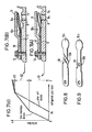
- Figs. 1 and 2 illustrate a rotary compressor for a refrigerator, e.g. as disclosed in Japanese Laid-Open Utility Model Publication No. 57-174773, wherein a closed housing 1 contains a motor 2 and a compressor -unit 3 comprising a cylinder 4, a crankshaft 5, a rolling piston 6, a radially slidable vane (not shown), and bearing end plates 7a, 7b closing the opposite ends of the cylinder to define a compression chamber A .and support the crankshaft.
- the end plate 7a has a port 8 defined therein for discharging the refrigerant from the compression chamber A into the space within the housing.
- a valve plate 9 mounted on the end plate 7a has a free end 9a for opening and closing the discharge port 8.
- a leaf spring is superposed on and fixed to the valve plate for biasing the valve plate 7a to a closed position.
- a known leaf spring 10 is shown in Figures 3 and 4 and has a free end 10a for biasing the free end 9a of the valve plate into a closed position.
- a valve holder 11 is fastened by a bolt 12 to fix the opposite ends of the valve plate 9 and the leaf spring 10 to the bearing end plate 7a as shown in Fig. 3.
- the leaf spring has an intermediate bend at 10b for establishing its biasing force.
- the natural frequencies of the leaf spring and the valve plate are varied to reduce noises due to frictional damping forces generated between their contacting surfaces.
- the timing of the opening of the refrigerant discharge port is delayed by an interval corresponding to the resistance imposed by the leaf spring.
- the pressure in the cylinder 4 thus builds up to a higher level than the internal pressure in the housing, resulting in a so-called "overshoot" which requires an extra amount of drive power and lowers the efficiency of the compressor.
- FIGs. 5 and 6 illustrate a refrigerant discharge valve according to a first embodiment of the invention.
- a bearing end plate 7a has a refrigerant discharge port 8.
- a valve plate 9 mounted on the end plate 7a has a free end 9a for opening and closing the discharge port.
- a leaf spring 10 is superposed on the valve plate 9.
- a valve holder 11 is fastened by a bolt 12 to fix the opposite ends of the valve plate and the leaf spring to the end plate 7a as shown in Fig. 5.
- the leaf spring has a free end 10a, and a downwardly bent portion at an intermediate position 10b between the fixed and free ends thereof.
- the bent portion has a press point 10c which bears on an intermediate zone of the valve plate 9 to bias it downwardly against the end plate 7a.
- the first and second phases of valve plate movement are represented in the force deflection diagram of Fig. 7 (C) and contrasted with the prior art.
- the first and second phases correspond to curve segments 51 and 52 respectively, whilst segment 53 shows the end phase in which both leaf spring 10 and valve plate 9 are strongly flexed upwardly against valve holder 11.
- the discharge valve of Figures 5 and 6 is not so constantly biased and thus opens at an earlier time, thereby reducing or substantially eliminating the opening pressure overshoot and reducing the compressor drive power. Since no leaf spring force acts on the free end of the valve plate during its initial flexing, the flow speed of the refrigerant through the discharge port is lowered, and hence any noise resulting from the refrigerant flow through the port is also reduced.
- the deformed portion of the spring 10 comprises a vertically bent intermediate step, it may also comprise a U-shaped groove as shown in Fig. 8 or a circular projection as shown in Fig. 9. Moreover, the portion of the leaf spring extending from the press point 10c to the free end 10a may be simply omitted or eliminated, depending upon the flexural characteristics of the particular spring employed.
- a refrigerant discharge valve including a leaf spring for biasing a valve plate, the leaf spring having a deformed portion for establishing a biasing force, but wherein the spring engages the valve plate at an intermediate zone thereof, and the free end of the valve plate is not subjected to any spring pressure during the initial opening of the refrigerant discharge port.
Landscapes
- Engineering & Computer Science (AREA)
- General Engineering & Computer Science (AREA)
- Mechanical Engineering (AREA)
- Compressor (AREA)
- Check Valves (AREA)
- Applications Or Details Of Rotary Compressors (AREA)
Abstract
Description
- This invention relates to a discharge valve arrangement suitable for a refrigerant compressor having a compression chamber bounded by a wall plate having a discharge port, said arrangement comprising: a resiliently flexible valve plate having a displaceable end portion for opening and closing said port; and
a spring means arranged to bias said valve plate against said wall plate. - In a known rotary compressor for a refrigerator, as shown in Japanese Utility Model Publication No. 57-A-174773, a valve plate for opening and closing a discharge port between a compression chamber and a housing space is biased by a leaf spring to a closed position. Contact between the valve plate and the leaf spring gives rise to frictional damping.
- In the known construction, the leaf spring applies bias force to the free end of the valve plate with the consequence that opening of the discharge port is delayed owing to the resistance of the spring. As a result, pressure in the cyclinder builds up to a higher level than internal housing pressure (so-called overshoot) which increases the power required for driving and lowers efficiency.
- Furthermore, the frictional damping forces between contacting surfaces of the leaf spring and valve plate give rise to noisy operation, although this can be reduced by appropriate selection and adjustment of the natural frequencies of the leaf spring and valve plate.
- An object of this invention is to provide a refrigerant discharge valve which increases the efficiency of the compressor.
- Another object of the invention is to provide a refrigerant discharge valve which reduces operational noise.
- A further object of the invention is to provide a refrigerant discharge valve which produces substantially no overshoot.
- A yet further object of the invention is to provide a refrigerant discharge valve which minimizes power requirements.
- According to the invention, the valve arrangement defined in the first paragraph of the specification is characterized in that said valve plate is biased by said spring means in such manner that said end portion is displaceable for opening said port substantially free of bias from said spring means.
- For a better understanding of the invention, and to show how the same may be carried into effect, reference will now be made, by way of example, to the accompanying drawings, in which:
- Fig. 1 is an axial cross-sectional view of a refrigerant compressor incorporating a discharge valve;
- Fig. 2 is a cross-sectional view taken along line II-II of Fig. 1;
- Fig. 3 is an enlarged cross-sectional view of a known valve arrangement taken along line III-III of Fig. 2; .
- Fig. 4 is an exploded cross-sectional view of the refrigerant discharge valve of Fig. 3;
- Fig. 5 is an enlarged cross-sectional view similar to Figure 3 of a refrigerant compressor discharge valve according to one embodiment of the present invention;
- Fig. 6 is an exploded cross-sectional view of the discharge valve illustrated in Fig. 5;
- Figs. 7(A), 7(B) and 7(C) are diagrams showing the comparative degrees of flexing of a discharge valve plate according to one embodiment of the invention and according to the prior art; and
- Figs. 8 and 9 are perspective views of leaf spring configurations for use in further embodiments of the invention.
- Figs. 1 and 2 illustrate a rotary compressor for a refrigerator, e.g. as disclosed in Japanese Laid-Open Utility Model Publication No. 57-174773, wherein a closed housing 1 contains a motor 2 and a compressor -
unit 3 comprising a cylinder 4, a crankshaft 5, a rolling piston 6, a radially slidable vane (not shown), and bearingend plates end plate 7a has aport 8 defined therein for discharging the refrigerant from the compression chamber A into the space within the housing. Avalve plate 9 mounted on theend plate 7a has afree end 9a for opening and closing thedischarge port 8. A leaf spring is superposed on and fixed to the valve plate for biasing thevalve plate 7a to a closed position. - A known
leaf spring 10 is shown in Figures 3 and 4 and has afree end 10a for biasing thefree end 9a of the valve plate into a closed position. Avalve holder 11 is fastened by abolt 12 to fix the opposite ends of thevalve plate 9 and theleaf spring 10 to thebearing end plate 7a as shown in Fig. 3. The leaf spring has an intermediate bend at 10b for establishing its biasing force. - In operation, when the motor 2 is energized the crankshaft 5 is driven thereby to rotate the exen- trically mounted piston 6 and compress the refrigerant gas in the cylinder 4 as the volume of the chamber A varies. When the internal pressure in the compression chamber exceeds the sum of the pressure in the closed housing 1 and the biasing force of the
leaf spring 10, the free ends of thevalve plate 9 and the leaf spring flex upwardly to open thedischarge port 8 and allow the compressed refrigerant gas to discharge into the housing. - By varying the thickness and/or shape of the
leaf spring 10 with respect to thevalve plate 9, the natural frequencies of the leaf spring and the valve plate are varied to reduce noises due to frictional damping forces generated between their contacting surfaces. - With the construction of the conventional refrigerant discharge valve, the timing of the opening of the refrigerant discharge port is delayed by an interval corresponding to the resistance imposed by the leaf spring. The pressure in the cylinder 4 thus builds up to a higher level than the internal pressure in the housing, resulting in a so-called "overshoot" which requires an extra amount of drive power and lowers the efficiency of the compressor.
- Figs. 5 and 6 illustrate a refrigerant discharge valve according to a first embodiment of the invention. A
bearing end plate 7a has arefrigerant discharge port 8. - A
valve plate 9 mounted on theend plate 7a has afree end 9a for opening and closing the discharge port. Aleaf spring 10 is superposed on thevalve plate 9. Avalve holder 11 is fastened by abolt 12 to fix the opposite ends of the valve plate and the leaf spring to theend plate 7a as shown in Fig. 5. The leaf spring has afree end 10a, and a downwardly bent portion at anintermediate position 10b between the fixed and free ends thereof. The bent portion has apress point 10c which bears on an intermediate zone of thevalve plate 9 to bias it downwardly against theend plate 7a. When assembled as shown in Fig. 5, thefree end 10a of the leaf spring is held against the lower surface of thevalve holder 11. Thus, no spring force is applied to thefree end 9a of the valve plate, at least during the initial opening of therefrigerant discharge port 8. - As soon as the pressure in the compression chamber A reaches the internal pressure in the housing 1, that is, when the compressed refrigerant gas load F on the plate equals zero, the
valve plate 9 starts to flex as shown in Figure 7 (A). In this first phase the free end of the valve plate flexes without any biasing force from theleaf spring 10. Thereafter, in a second phase, with the parts in the condition as shown in Fig. 7(B), the biasing force from the spring acts on thevalve plate 9, which then flexes at a reduced rate as the refrigerant gas load increases. More specifically, the force from theleaf spring 10 acts on thevalve plate 9 through the bent portion of the spring. During the initial flexing of the valve plate no spring force is applied to itsfree end 9a. - The first and second phases of valve plate movement are represented in the force deflection diagram of Fig. 7 (C) and contrasted with the prior art. The first and second phases correspond to
curve segments segment 53 shows the end phase in which bothleaf spring 10 andvalve plate 9 are strongly flexed upwardly againstvalve holder 11. - Thus with this arrangement of Figures 5 and 6 the flexing of the
valve plate 9 at the time of discharging the compressed refrigerant varies through threeregions 51 through 53 as indicated by the solid line in Fig. 7(C), dependent on the load from the compressed refrigerant gas. - With a conventional discharge valve, the valve plate is always biased by the leaf spring and does not begin to flex until the compressed refrigerant gas load F = Fo, as indicated by the chain line in Fig. 7(C). The discharge valve of Figures 5 and 6 is not so constantly biased and thus opens at an earlier time, thereby reducing or substantially eliminating the opening pressure overshoot and reducing the compressor drive power. Since no leaf spring force acts on the free end of the valve plate during its initial flexing, the flow speed of the refrigerant through the discharge port is lowered, and hence any noise resulting from the refrigerant flow through the port is also reduced.
- In as much as the
leaf spring 10 is held at itsfree end 10a against thevalve holder 11 and at itspress point 10c against thevalve plate 9, it reduces noise due to frictional damping forces generated at the contact points, whilst the desired frictional damping effect is nevertheless retained. - While in the foregoing embodiment the deformed portion of the
spring 10 comprises a vertically bent intermediate step, it may also comprise a U-shaped groove as shown in Fig. 8 or a circular projection as shown in Fig. 9. Moreover, the portion of the leaf spring extending from thepress point 10c to thefree end 10a may be simply omitted or eliminated, depending upon the flexural characteristics of the particular spring employed. - Thus, there is provided a refrigerant discharge valve including a leaf spring for biasing a valve plate, the leaf spring having a deformed portion for establishing a biasing force, but wherein the spring engages the valve plate at an intermediate zone thereof, and the free end of the valve plate is not subjected to any spring pressure during the initial opening of the refrigerant discharge port. This arrangement reduces any delay in the timing of the opening of the discharge port by the free end of the valve plate.
Claims (11)
a spring means (10) arranged to bias said valve plate (9) against said wall plate (7a),
characterized in that said valve plate (9) is biased by said spring means (10) in such manner that said end portion (9a) is displaceable for opening said port (8) substantially free of bias from said spring means (10).
Applications Claiming Priority (2)
| Application Number | Priority Date | Filing Date | Title |
|---|---|---|---|
| JP186901/84 | 1984-09-06 | ||
| JP59186901A JPS6165973A (en) | 1984-09-06 | 1984-09-06 | Compressor refrigerant discharge valve device |
Publications (3)
| Publication Number | Publication Date |
|---|---|
| EP0174530A2 true EP0174530A2 (en) | 1986-03-19 |
| EP0174530A3 EP0174530A3 (en) | 1987-04-22 |
| EP0174530B1 EP0174530B1 (en) | 1990-04-11 |
Family
ID=16196659
Family Applications (1)
| Application Number | Title | Priority Date | Filing Date |
|---|---|---|---|
| EP85110520A Expired - Lifetime EP0174530B1 (en) | 1984-09-06 | 1985-08-21 | Refrigerant compressor discharge valve |
Country Status (4)
| Country | Link |
|---|---|
| US (1) | US4628963A (en) |
| EP (1) | EP0174530B1 (en) |
| JP (1) | JPS6165973A (en) |
| DE (1) | DE3577122D1 (en) |
Cited By (8)
| Publication number | Priority date | Publication date | Assignee | Title |
|---|---|---|---|---|
| FR2725770A1 (en) * | 1994-10-12 | 1996-04-19 | Abb Flakt | Air flow regulator for ventilation and air conditioning installations |
| CN1041342C (en) * | 1994-12-28 | 1998-12-23 | 东芝株式会社 | Rotary compressor |
| CN103541901A (en) * | 2012-07-10 | 2014-01-29 | 艾默生环境优化技术(苏州)有限公司 | Pressure control valve and scroll compressor |
| CN103703335A (en) * | 2011-07-21 | 2014-04-02 | 松下电器产业株式会社 | Cooling device, electronic equipment equipped with the same, and electric vehicle |
| CN104454543A (en) * | 2014-12-01 | 2015-03-25 | 广东美芝制冷设备有限公司 | Rotary compressor and bearing component thereof |
| WO2016058600A1 (en) * | 2014-10-14 | 2016-04-21 | Schaeffler Technologies AG & Co. KG | Control valve with check valve |
| WO2016082015A1 (en) * | 2014-11-25 | 2016-06-02 | Whirlpool S.A. | Reciprocating compressor valves arrangement |
| EP3330544A1 (en) * | 2016-11-30 | 2018-06-06 | Mitsubishi Heavy Industries Thermal Systems, Ltd. | Compressor |
Families Citing this family (36)
| Publication number | Priority date | Publication date | Assignee | Title |
|---|---|---|---|---|
| JPH0631629B2 (en) * | 1987-03-09 | 1994-04-27 | 三菱電機株式会社 | Rotary compressor |
| GB8820524D0 (en) * | 1988-08-31 | 1988-09-28 | Grovag Grossventiltech | Seals for gas isolators |
| US5015161A (en) * | 1989-06-06 | 1991-05-14 | Ford Motor Company | Multiple stage orbiting ring rotary compressor |
| US5135368A (en) * | 1989-06-06 | 1992-08-04 | Ford Motor Company | Multiple stage orbiting ring rotary compressor |
| BR9002967A (en) * | 1990-06-19 | 1991-12-24 | Brasil Compressores Sa | VALVE FOR HERMETIC COOLING COMPRESSOR |
| KR930005874Y1 (en) * | 1991-01-31 | 1993-09-01 | 삼성전자 주식회사 | Compressor |
| JP3110455B2 (en) * | 1992-03-03 | 2000-11-20 | 松下冷機株式会社 | Hermetic compressor |
| JPH08193575A (en) * | 1995-01-13 | 1996-07-30 | Sanden Corp | Valve plate device |
| KR200154567Y1 (en) * | 1995-06-03 | 1999-08-16 | 윤종용 | Compression valve device of compressor |
| KR0161094B1 (en) * | 1995-09-05 | 1999-03-20 | 구자홍 | Valve device of hermetic compressor |
| US5823870A (en) * | 1996-07-03 | 1998-10-20 | Chrysler Corporation | Method and apparatus for reducing exhaust flap movement |
| US5769126A (en) * | 1996-09-12 | 1998-06-23 | Samsung Electronics Co., Ltd. | Discharge valve assembly in a reciprocating compressor |
| US5934305A (en) * | 1996-09-12 | 1999-08-10 | Samsung Electronics Co., Ltd. | Method of manufacturing a reciprocating compressor |
| JPH10103243A (en) * | 1996-10-01 | 1998-04-21 | Sanden Corp | Valve structure of compressor |
| US5848615A (en) * | 1996-12-04 | 1998-12-15 | Ingersoll-Rand Company | Check valve cartridge for fluid pump |
| US6309194B1 (en) | 1997-06-04 | 2001-10-30 | Carrier Corporation | Enhanced oil film dilation for compressor suction valve stress reduction |
| US6468060B1 (en) | 1998-03-02 | 2002-10-22 | Carrier Corporation | Oil film dilation for compressor suction valve stress reduction |
| US6099275A (en) * | 1998-04-15 | 2000-08-08 | Carrier Corporation | Biased open suction valve |
| US6565336B1 (en) | 1998-05-06 | 2003-05-20 | Carrier Corporation | Normally unseated suction valve |
| US6102680A (en) * | 1998-07-01 | 2000-08-15 | Carrier Corporation | Suction valve with release timing chamber |
| DE19840098A1 (en) * | 1998-09-03 | 2000-03-09 | Asea Brown Boveri | Method and device for relieving the thrust of a turbocharger |
| FR2798965B1 (en) * | 1999-09-28 | 2001-12-07 | Tecumseh Europe Sa | DISCHARGE VALVE DEVICE FOR REFRIGERANT FLUID COMPRESSOR |
| FR2800831B1 (en) * | 1999-11-05 | 2002-02-15 | Tecumseh Europe Sa | DISCHARGE VALVE DEVICE FOR A FLUID COMPRESSOR |
| KR100408997B1 (en) * | 2000-12-28 | 2003-12-06 | 엘지전자 주식회사 | Compressor |
| KR100422363B1 (en) * | 2001-06-29 | 2004-03-12 | 삼성광주전자 주식회사 | Valve assembly for compressor |
| JP4928447B2 (en) * | 2004-06-24 | 2012-05-09 | ルーク アウトモービルテヒニーク ゲゼルシャフト ミット ベシュレンクテル ハフツング ウント コンパニー コマンディトゲゼルシャフト | pump |
| JP4752257B2 (en) * | 2004-12-08 | 2011-08-17 | パナソニック株式会社 | Hermetic compressor |
| WO2007116989A1 (en) * | 2006-04-06 | 2007-10-18 | Panasonic Corporation | Hermetic compressor |
| WO2009027000A1 (en) * | 2007-08-25 | 2009-03-05 | Ixetic Mac Gmbh | Reciprocating piston machine |
| JP5107145B2 (en) * | 2008-06-10 | 2012-12-26 | 日立アプライアンス株式会社 | Hermetic compressor |
| JP5414088B2 (en) * | 2008-06-17 | 2014-02-12 | サンデン株式会社 | Compressor |
| EP2318713A1 (en) * | 2008-08-21 | 2011-05-11 | Ixetic Mac Gmbh | Reciprocating piston engine |
| CN103748361B (en) * | 2011-08-24 | 2016-03-09 | 松下电器产业株式会社 | Control valve unit and the hermetic type compressor possessing this control valve unit of compressor |
| US9863422B2 (en) | 2013-12-17 | 2018-01-09 | Magna Powertrain Bad Homburg GmbH | Vacuum pump outlet valve |
| CN113586772A (en) * | 2020-04-30 | 2021-11-02 | 艾默生环境优化技术(苏州)有限公司 | Valve assembly and compressor |
| TWI789742B (en) * | 2021-04-16 | 2023-01-11 | 周文三 | Air compressor |
Family Cites Families (9)
| Publication number | Priority date | Publication date | Assignee | Title |
|---|---|---|---|---|
| US2000883A (en) * | 1932-03-07 | 1935-05-07 | Alfred F Pillsbury | Valve |
| US2118356A (en) * | 1935-03-07 | 1938-05-24 | Crosiey Radio Corp | One-way valve |
| US2161769A (en) * | 1936-03-23 | 1939-06-06 | Mills Novelty Co | Discharge valve for compressors and the like |
| FR997033A (en) * | 1949-10-07 | 1951-12-31 | Compressor valve | |
| NL108432C (en) * | 1959-03-23 | 1900-01-01 | ||
| FR1492539A (en) * | 1966-09-13 | 1967-08-18 | New York Air Brake Co | Valve, in particular for vacuum pump |
| DE2309228A1 (en) * | 1973-02-24 | 1974-08-29 | Bosch Gmbh Robert | LEAF SPRING VALVE TONGUE AS VALVE CLOSING BODY OF A COMPRESSOR INLET OR OUTLET VALVE |
| AT350701B (en) * | 1975-10-06 | 1979-06-11 | Hoerbiger Ventilwerke Ag | SUPPORT FOR THE LAMELLA OF A LAMELLA VALVE |
| DE3100886A1 (en) * | 1981-01-14 | 1982-08-05 | Fichtel & Sachs Ag, 8720 Schweinfurt | HYDRAULIC VIBRATION DAMPER WITH LOW-NOISE SHOCK VALVES |
-
1984
- 1984-09-06 JP JP59186901A patent/JPS6165973A/en active Pending
-
1985
- 1985-07-22 US US06/757,418 patent/US4628963A/en not_active Expired - Fee Related
- 1985-08-21 DE DE8585110520T patent/DE3577122D1/en not_active Expired - Lifetime
- 1985-08-21 EP EP85110520A patent/EP0174530B1/en not_active Expired - Lifetime
Cited By (14)
| Publication number | Priority date | Publication date | Assignee | Title |
|---|---|---|---|---|
| FR2725770A1 (en) * | 1994-10-12 | 1996-04-19 | Abb Flakt | Air flow regulator for ventilation and air conditioning installations |
| CN1041342C (en) * | 1994-12-28 | 1998-12-23 | 东芝株式会社 | Rotary compressor |
| CN103703335B (en) * | 2011-07-21 | 2015-12-02 | 松下电器产业株式会社 | Cooling device, electronic equipment equipped with the same, and electric vehicle |
| CN103703335A (en) * | 2011-07-21 | 2014-04-02 | 松下电器产业株式会社 | Cooling device, electronic equipment equipped with the same, and electric vehicle |
| EP2735834A4 (en) * | 2011-07-21 | 2014-12-10 | Panasonic Corp | COOLING APPARATUS, ELECTRONIC APPARATUS EQUIPPED WITH SAME, AND ELECTRIC VEHICLE |
| CN103541901B (en) * | 2012-07-10 | 2015-10-07 | 艾默生环境优化技术(苏州)有限公司 | Pressure control valve and scroll compressor |
| CN103541901A (en) * | 2012-07-10 | 2014-01-29 | 艾默生环境优化技术(苏州)有限公司 | Pressure control valve and scroll compressor |
| US10072659B2 (en) | 2012-07-10 | 2018-09-11 | Emerson Climate Technologies (Suzhou) Co., Ltd. | Pressure control valve and scroll compressor |
| WO2016058600A1 (en) * | 2014-10-14 | 2016-04-21 | Schaeffler Technologies AG & Co. KG | Control valve with check valve |
| US10260383B2 (en) | 2014-10-14 | 2019-04-16 | Schaeffler Technologies AG & Co. KG | Control valve with check valve |
| WO2016082015A1 (en) * | 2014-11-25 | 2016-06-02 | Whirlpool S.A. | Reciprocating compressor valves arrangement |
| US10174756B2 (en) | 2014-11-25 | 2019-01-08 | Whirlpool S.A. | Reciprocating compressor valves arrangement |
| CN104454543A (en) * | 2014-12-01 | 2015-03-25 | 广东美芝制冷设备有限公司 | Rotary compressor and bearing component thereof |
| EP3330544A1 (en) * | 2016-11-30 | 2018-06-06 | Mitsubishi Heavy Industries Thermal Systems, Ltd. | Compressor |
Also Published As
| Publication number | Publication date |
|---|---|
| DE3577122D1 (en) | 1990-05-17 |
| EP0174530B1 (en) | 1990-04-11 |
| EP0174530A3 (en) | 1987-04-22 |
| US4628963A (en) | 1986-12-16 |
| JPS6165973A (en) | 1986-04-04 |
Similar Documents
| Publication | Publication Date | Title |
|---|---|---|
| EP0174530A2 (en) | Refrigerant compressor discharge valve | |
| US4978285A (en) | Reed valve for hermetic compressor | |
| CA2124655C (en) | Refrigerator compressor having a spherical discharge valve | |
| JPS636757B2 (en) | ||
| JPH0353477B2 (en) | ||
| US5370156A (en) | Reduced noise valve stop | |
| CN1005039B (en) | Discharge valve of refrigeration compressor | |
| US5720601A (en) | Valve apparatus of hermetic type compressor | |
| GB2163236A (en) | A compressor | |
| US20030075224A1 (en) | High efficient valve assembly of compressor | |
| JPH10184547A (en) | Valve device for hermetic compressor | |
| US5738502A (en) | Valve keeper for a valve of a reciprocating compressor | |
| KR970045523A (en) | Valve type discharge mechanism of fluid displacement device | |
| CN100376795C (en) | hermetic compressor | |
| JP3026692B2 (en) | Compressor | |
| CN102626985B (en) | Manufacturing method of sealing component and forming device | |
| KR100194142B1 (en) | Lead valve device and hermetic reciprocating compressor having same | |
| KR100631531B1 (en) | Discharge valve device of the compressor | |
| KR0119847Y1 (en) | Discharge valve device of hermetic compressor | |
| JPH06257568A (en) | Sealed compressor | |
| CN109779882B (en) | Exhaust assembly for linear compressor and linear compressor | |
| JP2790489B2 (en) | Valve device for reciprocating compressor | |
| KR100216193B1 (en) | Compressor | |
| KR100531897B1 (en) | Supporting structure for spring in reciprocating compressor | |
| RU2107860C1 (en) | Straightway valve |
Legal Events
| Date | Code | Title | Description |
|---|---|---|---|
| PUAI | Public reference made under article 153(3) epc to a published international application that has entered the european phase |
Free format text: ORIGINAL CODE: 0009012 |
|
| AK | Designated contracting states |
Kind code of ref document: A2 Designated state(s): DE FR GB IT SE |
|
| PUAL | Search report despatched |
Free format text: ORIGINAL CODE: 0009013 |
|
| AK | Designated contracting states |
Kind code of ref document: A3 Designated state(s): DE FR GB IT SE |
|
| 17P | Request for examination filed |
Effective date: 19870622 |
|
| 17Q | First examination report despatched |
Effective date: 19880915 |
|
| GRAA | (expected) grant |
Free format text: ORIGINAL CODE: 0009210 |
|
| AK | Designated contracting states |
Kind code of ref document: B1 Designated state(s): DE FR GB IT SE |
|
| ITF | It: translation for a ep patent filed | ||
| REF | Corresponds to: |
Ref document number: 3577122 Country of ref document: DE Date of ref document: 19900517 |
|
| ET | Fr: translation filed | ||
| PLBE | No opposition filed within time limit |
Free format text: ORIGINAL CODE: 0009261 |
|
| STAA | Information on the status of an ep patent application or granted ep patent |
Free format text: STATUS: NO OPPOSITION FILED WITHIN TIME LIMIT |
|
| 26N | No opposition filed | ||
| ITTA | It: last paid annual fee | ||
| EAL | Se: european patent in force in sweden |
Ref document number: 85110520.5 |
|
| ITPR | It: changes in ownership of a european patent |
Owner name: OFFERTA DI LICENZA AL PUBBLICO |
|
| REG | Reference to a national code |
Ref country code: GB Ref legal event code: 746 Effective date: 19960611 |
|
| REG | Reference to a national code |
Ref country code: FR Ref legal event code: D6 |
|
| PGFP | Annual fee paid to national office [announced via postgrant information from national office to epo] |
Ref country code: SE Payment date: 19980806 Year of fee payment: 14 |
|
| PGFP | Annual fee paid to national office [announced via postgrant information from national office to epo] |
Ref country code: GB Payment date: 19980812 Year of fee payment: 14 |
|
| PGFP | Annual fee paid to national office [announced via postgrant information from national office to epo] |
Ref country code: FR Payment date: 19980814 Year of fee payment: 14 |
|
| PGFP | Annual fee paid to national office [announced via postgrant information from national office to epo] |
Ref country code: DE Payment date: 19980831 Year of fee payment: 14 |
|
| PG25 | Lapsed in a contracting state [announced via postgrant information from national office to epo] |
Ref country code: GB Free format text: LAPSE BECAUSE OF NON-PAYMENT OF DUE FEES Effective date: 19990821 |
|
| PG25 | Lapsed in a contracting state [announced via postgrant information from national office to epo] |
Ref country code: SE Free format text: THE PATENT HAS BEEN ANNULLED BY A DECISION OF A NATIONAL AUTHORITY Effective date: 19990830 |
|
| GBPC | Gb: european patent ceased through non-payment of renewal fee |
Effective date: 19990821 |
|
| PG25 | Lapsed in a contracting state [announced via postgrant information from national office to epo] |
Ref country code: FR Free format text: LAPSE BECAUSE OF NON-PAYMENT OF DUE FEES Effective date: 20000428 |
|
| EUG | Se: european patent has lapsed |
Ref document number: 85110520.5 |
|
| PG25 | Lapsed in a contracting state [announced via postgrant information from national office to epo] |
Ref country code: DE Free format text: LAPSE BECAUSE OF NON-PAYMENT OF DUE FEES Effective date: 20000601 |
|
| REG | Reference to a national code |
Ref country code: FR Ref legal event code: ST |