EP0174254B1 - Dispositif mécanique destinés à améliorer les transferts thermiques et à prévenir l'encrassement des échangeurs de chaleur - Google Patents
Dispositif mécanique destinés à améliorer les transferts thermiques et à prévenir l'encrassement des échangeurs de chaleur Download PDFInfo
- Publication number
- EP0174254B1 EP0174254B1 EP85401696A EP85401696A EP0174254B1 EP 0174254 B1 EP0174254 B1 EP 0174254B1 EP 85401696 A EP85401696 A EP 85401696A EP 85401696 A EP85401696 A EP 85401696A EP 0174254 B1 EP0174254 B1 EP 0174254B1
- Authority
- EP
- European Patent Office
- Prior art keywords
- movable element
- tube
- rigid
- heat
- heat exchanger
- Prior art date
- Legal status (The legal status is an assumption and is not a legal conclusion. Google has not performed a legal analysis and makes no representation as to the accuracy of the status listed.)
- Expired
Links
- 239000012530 fluid Substances 0.000 claims abstract description 26
- 229910052751 metal Inorganic materials 0.000 claims abstract description 13
- 239000002184 metal Substances 0.000 claims abstract description 13
- 230000008878 coupling Effects 0.000 claims abstract 5
- 238000010168 coupling process Methods 0.000 claims abstract 5
- 238000005859 coupling reaction Methods 0.000 claims abstract 5
- 239000000463 material Substances 0.000 claims description 4
- 241000207836 Olea <angiosperm> Species 0.000 claims description 3
- 238000004519 manufacturing process Methods 0.000 claims description 3
- 229910000831 Steel Inorganic materials 0.000 claims description 2
- RTAQQCXQSZGOHL-UHFFFAOYSA-N Titanium Chemical compound [Ti] RTAQQCXQSZGOHL-UHFFFAOYSA-N 0.000 claims description 2
- 239000000956 alloy Substances 0.000 claims description 2
- 229910045601 alloy Inorganic materials 0.000 claims description 2
- 229910052782 aluminium Inorganic materials 0.000 claims description 2
- XAGFODPZIPBFFR-UHFFFAOYSA-N aluminium Chemical compound [Al] XAGFODPZIPBFFR-UHFFFAOYSA-N 0.000 claims description 2
- 230000035939 shock Effects 0.000 claims description 2
- 239000010959 steel Substances 0.000 claims description 2
- 239000010936 titanium Substances 0.000 claims description 2
- 229910052719 titanium Inorganic materials 0.000 claims description 2
- 239000004411 aluminium Substances 0.000 claims 1
- 230000000717 retained effect Effects 0.000 claims 1
- 240000007817 Olea europaea Species 0.000 description 6
- 239000010779 crude oil Substances 0.000 description 4
- 210000001015 abdomen Anatomy 0.000 description 3
- 230000007797 corrosion Effects 0.000 description 3
- 238000005260 corrosion Methods 0.000 description 3
- 239000000126 substance Substances 0.000 description 3
- 238000004804 winding Methods 0.000 description 3
- 230000015572 biosynthetic process Effects 0.000 description 2
- 230000000694 effects Effects 0.000 description 2
- 229930195733 hydrocarbon Natural products 0.000 description 2
- 150000002430 hydrocarbons Chemical class 0.000 description 2
- 229910052500 inorganic mineral Inorganic materials 0.000 description 2
- 238000005304 joining Methods 0.000 description 2
- 239000007788 liquid Substances 0.000 description 2
- 238000000034 method Methods 0.000 description 2
- 239000011707 mineral Substances 0.000 description 2
- 230000003071 parasitic effect Effects 0.000 description 2
- 239000003208 petroleum Substances 0.000 description 2
- 239000007787 solid Substances 0.000 description 2
- 230000002159 abnormal effect Effects 0.000 description 1
- 230000000903 blocking effect Effects 0.000 description 1
- 230000000295 complement effect Effects 0.000 description 1
- 230000036461 convulsion Effects 0.000 description 1
- 238000000354 decomposition reaction Methods 0.000 description 1
- 238000004821 distillation Methods 0.000 description 1
- 230000002349 favourable effect Effects 0.000 description 1
- 239000012212 insulator Substances 0.000 description 1
- 230000007774 longterm Effects 0.000 description 1
- 238000003754 machining Methods 0.000 description 1
- 230000014759 maintenance of location Effects 0.000 description 1
- 239000007769 metal material Substances 0.000 description 1
- 125000005608 naphthenic acid group Chemical group 0.000 description 1
- 238000013021 overheating Methods 0.000 description 1
- 210000004417 patella Anatomy 0.000 description 1
- 229920000642 polymer Polymers 0.000 description 1
- 230000003449 preventive effect Effects 0.000 description 1
- 230000001737 promoting effect Effects 0.000 description 1
- 230000001902 propagating effect Effects 0.000 description 1
- 238000000197 pyrolysis Methods 0.000 description 1
- 238000011084 recovery Methods 0.000 description 1
- 150000003839 salts Chemical class 0.000 description 1
- 239000000523 sample Substances 0.000 description 1
- 239000013049 sediment Substances 0.000 description 1
- 238000011144 upstream manufacturing Methods 0.000 description 1
Images
Classifications
-
- F—MECHANICAL ENGINEERING; LIGHTING; HEATING; WEAPONS; BLASTING
- F28—HEAT EXCHANGE IN GENERAL
- F28F—DETAILS OF HEAT-EXCHANGE AND HEAT-TRANSFER APPARATUS, OF GENERAL APPLICATION
- F28F21/00—Constructions of heat-exchange apparatus characterised by the selection of particular materials
- F28F21/08—Constructions of heat-exchange apparatus characterised by the selection of particular materials of metal
-
- B—PERFORMING OPERATIONS; TRANSPORTING
- B08—CLEANING
- B08B—CLEANING IN GENERAL; PREVENTION OF FOULING IN GENERAL
- B08B9/00—Cleaning hollow articles by methods or apparatus specially adapted thereto
- B08B9/02—Cleaning pipes or tubes or systems of pipes or tubes
- B08B9/027—Cleaning the internal surfaces; Removal of blockages
- B08B9/04—Cleaning the internal surfaces; Removal of blockages using cleaning devices introduced into and moved along the pipes
- B08B9/043—Cleaning the internal surfaces; Removal of blockages using cleaning devices introduced into and moved along the pipes moved by externally powered mechanical linkage, e.g. pushed or drawn through the pipes
- B08B9/045—Cleaning the internal surfaces; Removal of blockages using cleaning devices introduced into and moved along the pipes moved by externally powered mechanical linkage, e.g. pushed or drawn through the pipes the cleaning devices being rotated while moved, e.g. flexible rotating shaft or "snake"
-
- F—MECHANICAL ENGINEERING; LIGHTING; HEATING; WEAPONS; BLASTING
- F28—HEAT EXCHANGE IN GENERAL
- F28F—DETAILS OF HEAT-EXCHANGE AND HEAT-TRANSFER APPARATUS, OF GENERAL APPLICATION
- F28F13/00—Arrangements for modifying heat-transfer, e.g. increasing, decreasing
- F28F13/06—Arrangements for modifying heat-transfer, e.g. increasing, decreasing by affecting the pattern of flow of the heat-exchange media
- F28F13/12—Arrangements for modifying heat-transfer, e.g. increasing, decreasing by affecting the pattern of flow of the heat-exchange media by creating turbulence, e.g. by stirring, by increasing the force of circulation
- F28F13/125—Arrangements for modifying heat-transfer, e.g. increasing, decreasing by affecting the pattern of flow of the heat-exchange media by creating turbulence, e.g. by stirring, by increasing the force of circulation by stirring
-
- F—MECHANICAL ENGINEERING; LIGHTING; HEATING; WEAPONS; BLASTING
- F28—HEAT EXCHANGE IN GENERAL
- F28F—DETAILS OF HEAT-EXCHANGE AND HEAT-TRANSFER APPARATUS, OF GENERAL APPLICATION
- F28F19/00—Preventing the formation of deposits or corrosion, e.g. by using filters or scrapers
-
- F—MECHANICAL ENGINEERING; LIGHTING; HEATING; WEAPONS; BLASTING
- F28—HEAT EXCHANGE IN GENERAL
- F28G—CLEANING OF INTERNAL OR EXTERNAL SURFACES OF HEAT-EXCHANGE OR HEAT-TRANSFER CONDUITS, e.g. WATER TUBES OR BOILERS
- F28G3/00—Rotary appliances
- F28G3/08—Rotary appliances having coiled wire tools, i.e. basket type
-
- F—MECHANICAL ENGINEERING; LIGHTING; HEATING; WEAPONS; BLASTING
- F28—HEAT EXCHANGE IN GENERAL
- F28D—HEAT-EXCHANGE APPARATUS, NOT PROVIDED FOR IN ANOTHER SUBCLASS, IN WHICH THE HEAT-EXCHANGE MEDIA DO NOT COME INTO DIRECT CONTACT
- F28D21/00—Heat-exchange apparatus not covered by any of the groups F28D1/00 - F28D20/00
- F28D2021/0019—Other heat exchangers for particular applications; Heat exchange systems not otherwise provided for
- F28D2021/0059—Other heat exchangers for particular applications; Heat exchange systems not otherwise provided for for petrochemical plants
Definitions
- the present invention relates to improvements made to heat exchangers, with a view to improving heat transfers and preventing their rapid fouling.
- a first solution in particular described in US-A-4,174,750, consists in introducing a helical ribbon which scrapes the wall of the exchanger tube by turning on itself and puts the circulating fluid in total turbulence.
- the use of such a tape is not favorable, because it wears out the wall and, above all, its presence in the tube increases the pressure drop.
- the helical spring of judiciously chosen elasticity, is animated by a vibratory and / or rotational movement, caused by a non-continuous mechanical drive device following a back-and-forth movement, or simply by the action of the fluid flow circulating in these tubes.
- the elastic spring can move like a propagating wave either under the action of the back and forth movement due to the drive device, or under the action of the jerks of circulating fluid, when the flow flow is not constant, or even like a standing wave, under the action of a flow at constant flow.
- the elastic spring has knots and bellies over a portion of the length of the exchanger tube.
- the spring can touch the wall of the exchanger tube in a rotary movement around the axis of the exchanger tube. The wall is thus scraped at the points of contact with the bellies of the spring and is only cleaned at these points, in particular in the case of patent FR-A-2,479,964.
- the rotary movement is not a real rotation of the spring, but a torsion of the latter on itself, from a rigid attachment system. Indeed, the system of hooking the spring does not allow it to rotate freely, regardless of the direction of rotation, and independently of the point of attachment.
- the springs can break and be entrained by the fluid, thereby blocking the outlet and creating an abnormal increase in the pressure drop.
- the invention aims to propose a rigid and robust device, can be reused, which is not very sensitive to jolts in the flow and viscosity of the circulating fluid, and which creates little or no pressure drop.
- the subject of the present invention is a heat exchanger comprising a plurality of tubes in which a fluid circulates and in at least one of which is housed a movable element constituted by a metallic winding in the form of a solenoid, of which at least one of the ends is held in position by a fastening system such that said mobile element can be driven in rotation by the fluid, in order to prevent fouling of said tube and to improve heat transfers,
- this exchanger being characterized in that said element mobile in the form of a solenoid is undeformable and rigid, so that it can be rotated without coming into contact with the internal wall of said tube during its movement, while said attachment system comprises a means of attachment external to said exchanger tube and a mechanical connection allowing the free rotation of said movable element on itself, around the axis of said exchanger tube.
- the term “mobile, non-deformable and rigid element” means a mobile which cannot be deformed under the action of the fluid, under normal conditions of operation of the exchanger tubes.
- the mobile is not deformed when the circulating fluid has variations in speed, viscosity and / or temperature.
- the mobile is rigid, it never touches the wall of the tube by turning on itself, which prevents wear of the latter.
- the reduced size of the mobile makes it possible to best limit the pressure drop, and thus to improve the economy of the process.
- a person skilled in the art can manufacture it from a material resistant to temperature and thermal shock, preferably from a metal such as titanium, aluminum, steel. or an alloy, this metallic material possibly having been heat-treated in order to improve its physico-chemical properties.
- attachment system for the mobile means a system comprising a means for fixing the device and a mechanical connection comprising a mechanical articulation allowing the rotation of the mobile on itself.
- the mechanical articulation allowing the rotation of the mobile can consist of an articulated ball joint, of which, for example, a part corresponds to the free end of a rigid rod connected by means fixing the device by a means known per se, and the other part of which corresponds to one of the ends of the mobile.
- Another embodiment of the mechanical joint comprises a hollow olive pierced at both ends of its largest axis of revolution.
- the holes allow, on the one hand, the retention of the ends, in a manner known per se, of the mobile and of the rigid rod connected to the fixing means, on the other hand, the independent rotations of the olive relative to the rod and mobile compared to the olive.
- the mechanical articulation can also be constituted by a stirrup rigidly connected, for example, by means of fixing using a rigid rod, one part joining the branches of the stirrup and which serves as a support during normal use thereof is pierced with a hole in which the end of the mobile, terminated in a protrusion of section greater than that of the hole, can rotate freely independently of the fixing means.
- the fixing means is pierced with a light through which a metal rod can rotate freely in the latter, and comprising at one end a round head of diameter greater than that of the hole and the second end of which can be connected to mobile.
- the probe terminating the same metal rod is embedded in the fixing means.
- the means of fixing the device will be generally disposed along the axis of the exchanger tube, so that the rotation of the movable element on itself takes place around this axis. It can be specific to each tube or common to all the tubes on the same side of the exchanger. It can be materialized for example by the anchor point of a rigid rod, according to a mode known per se, on a wire or at the intersection of two wires, these wires being able to be fixed along the diameters of a crown circular or of a ring positioned coaxially on the exchanger tube or which can advantageously form part of a grid placed over the entire section of the exchanger.
- the grid can be judiciously replaced by a succession of parallel sections between them, distributed in front of the orifices of the tubes, the fixing of the mobile via the mechanical connection being done, for example, by fixing according to a mode known per se of the rigid rod resulting from the mechanical connection, or by embedding a part of the mechanical connection in the profile, in particular by embedding the olive, the stirrup, the cardan or the part female patella.
- these sections constituting the means for fixing the device may have dimensions and a shape suitable for minimizing the size of the section of the exchanger and allowing free circulation of the fluid.
- the use of a device according to the invention in an exchanger tube is particularly advantageous, since the mobile in rotation has the effect of increasing the turbulence of the fluid circulating mainly at the periphery of the tube, of homogenizing its temperature over the entire section of the tube, thus avoiding the creation of hot spots on the wall of the tube and consequently considerably reducing the risks of formation of a deposit.
- the rotating mobile can be inscribed in a fictitious cylinder of diameter d f smaller than the diameter d, of the exchanger tube in which it is placed.
- the diameters d f and d t in order to turbulence the fluid as far as the internal wall of the exchanger tube and thus avoid hot spots, the diameters d f and d t will be such that the ratio d f / d t is between 0.1 and 0.9 and preferably between 0.5 and 0.9.
- the mobile does not touch the wall of the tube at any time, and it does not scratch it, and therefore it does not create parasitic roughness thereon, promoting any corrosion phenomenon.
- the device according to the invention is advantageous in that it has a preventive role, because its use minimizes the formation of deposits and does not increase parasitic phenomena such as corrosion, and that it resists sudden variations in the flow rate and viscosity of the circulating fluid, the mobile rotating more or less quickly without breaking.
- Another advantage of the invention is that the mobile of the device can be connected, upstream or downstream of the flow of circulating fluid or even by its two ends, to one or two fixing means using mechanical connections allowing the rotation.
- the mobile can be made entirely from a rigid metal rod which, after machining, can be in the form of a rigid helical winding, such as a pitch solenoid regular or not.
- a rigid helical winding such as a pitch solenoid regular or not.
- the mobile turns in the opposite direction of the pitch, with a speed which depends on its weight, the flow rate and the viscosity of the circulating fluid.
- the shape of the mobile can vary from one exchanger to another depending on the nature of the fluid. For a given mobile, there is a minimum speed of the circulating fluid, allowing the mobile to rotate.
- the device according to the invention can be introduced into any tube traversed by a fluid, whatever its pressure, this fluid being able to be an organic or mineral liquid, but also a gas.
- the temperature of the tube can be as high as 400-500 ° C, if the nature of the material constituting the mobile allows it.
- these devices can be installed in the heat exchanger tubes, in the pyrolysis tubes.
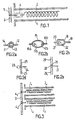
- FIG. 1 represents an embodiment of the device according to the invention, housed in a tube 1 of heat exchanger.
- This device comprises a mobile 2, connected by means of a mechanical articulation 4 to a rigid rod 5, fixed on a member 3.
- the connection between the mobile 2 and the mechanical articulation 4 is such that the mobile 2 can rotate freely on itself, relative to the articulation 4.
- This articulation 4 can, in certain cases, pivot freely relative to the rod 5.
- the mobile 2 is constituted by a rigid metal rod wound in the form of a solenoid, which allows it to rotate under the stress of the fluid circulating in the tube 1.
- the articulation shown in FIG. 2a comprises a ball joint of which a solid spherical part 13, integral with a rod 12, is housed in a spherical recess of complementary shape, 11, integral with a rod 14.
- the rods 12 and 14 can indifferently be integral with, or constituted by, the rod 5 and the end of the mobile 2 of FIG. 1.
- the articulation comprises a hollow olive 15, pierced along its major axis of revolution, with two orifices in which two rods 16a, 16b are engaged, held integral with the olive 15 by two heads 17a. 17b, housed inside it.
- the rods 16a and 16b can indifferently be integral with or constituted by the rod 5 and the end of the mobile 2 in FIG. 1.
- FIG. 2c is shown another embodiment of the articulation of the device according to the invention, comprising a stirrup 18 rigidly secured to a rod 19.
- the rectilinear part 20 joining the branches of the stirrup is pierced with a light in which is engaged a rod 21, which a head 22 holds integral with the stirrup.
- the rods 19 and 21 can be made indifferently integral with the rod 5 or the end of the mobile 2 of FIG. 1 or be formed by these.
- a metal rod 24 passes through the fixing means 25 and ends in a round head 23 of diameter greater than the passage hole of the rod, the other end of the rod 24 is connected to the mobile 2.
- the round head 26 of the metal rod 27 is embedded in the cavity 28 of the fixing means 29.
- FIG. 3 represents a part of an exchanger, the tubes 1 1 and 1 2 , parallel and situated on the same line, are equipped with devices which are objects of the invention, the mobile elements 2 1 and 2 2 of which are stiffened by adding rigid rods at the periphery of the solenoid. They have the same fixing means 3, consisting of the same metal profile, in which are embedded the hollow olives 4 1 and 4 2 of the mechanical connections. These olives are fixed, but they allow the free and permanent rotation of mobiles 2 1 and 2 ⁇ .
Landscapes
- Engineering & Computer Science (AREA)
- Mechanical Engineering (AREA)
- General Engineering & Computer Science (AREA)
- Physics & Mathematics (AREA)
- Thermal Sciences (AREA)
- Chemical & Material Sciences (AREA)
- Combustion & Propulsion (AREA)
- Heat-Exchange Devices With Radiators And Conduit Assemblies (AREA)
- Heat Treatment Of Articles (AREA)
Description
- La présente invention concerne des perfectionnements apportés aux échangeurs de chaleur, en vue d'améliorer les transferts thermiques et de prévenir leur encrassement rapide.
- Il est connu, dans l'industrie, que les transferts thermiques diminuent au cours du temps, car les tubes d'échangeurs s'encrassent, leurs parois internes se recouvrant progressivement d'une substance solide, ou dépôt, agissant comme isolant thermique à faible conductivité thermique. Ce dépôt provient généralement de la surchauffe du fluide sur les parois internes des tubes qu'il traverse, mais aussi des effets de la corrosion. Les industriels de la chimie, de la pétrochimie et du pétrole observent de tels dépôts, provenant de la décomposition de produits organiques du type des polymères ou des hydrocarbures et de produits minéraux à l'état liquide.
- Par ailleurs, l'industrie agro-alimentaire provoque également de tels dépôts et s'intéresse à ces problèmes.
- Dans l'industrie pétrolière, les techniciens se sont appliqués, ces dernières années, à mieux intégrer leurs unités, en vue de récupérer le maximum d'énergie, par exemple en préchauffant un pétrole brut par le résidu atmosphérique sortant chaud de l'unité de distillation atmosphérique. Or ce type de récupération d'énergie nécessite l'emploi d'échangeurs, dans lesquels les transferts thermiques doivent être très bons. Les pétroles bruts traités dans une raffinerie sont souvent d'origine très diverse et, parmi eux, de nombreux pétroles bruts, dits lourds, sont très riches en sédiments, en sels et en acides naphté- niques, donc très corrosifs et sujets à former des dépôts sur les parois internes des tubes d'échangeurs à l'intérieur desquels ils circulent généralement. Certains résidus atmosphériques, en mélange dans les pétroles bruts, ont tendance à former des dépôts en se condensant sur les parois des tubes d'échangeurs. L'emploi de ces hydrocarbures lourds, difficiles à traiter, tend donc à accroître la vitesse d'encrassement des tubes d'échangeurs, à augmenter plus rapidement la résistance au transfert thermique et, par suite, à diminuer l'efficacité des transferts thermiques.
- Plusieurs solutions à ce problème ont été envisagées. Une première solution, notamment décrite dans le brevet US-A-4 174 750, consiste à introduire un ruban hélicoïdal qui gratte la paroi du tube échangeur en tournant sur lui-même et met le fluide circulant en totale turbulence. L'utilisation d'un tel ruban n'est pas favorable, car il use la paroi et, surtout, sa présence dans le tube augmente la perte de charge.
- Un dispositif analogue, dans son principe, est décrit dans Betriebstechnik, vol. 23, Juin 1983, n° 1, page 6, « Denkbar einfache Lôsung. » Une deuxième solution consiste à introduire dans chaque tube d'échangeur un ressort élastique, généralement hélicoïdal, tendu entre deux points ou maintenu à l'une de ses extrémités à l'aide d'une liaison rigide, comme dans les brevets français FR-A-2 435 292 et FR-A-2 479 964.
- Selon ces deux brevets, le ressort hélicoïdal, d'élasticité judicieusement choisie, est animé d'un mouvement vibratoire et/ou de rotation, provoqué par un dispositif mécanique d'entraînement non continu suivant un mouvement de va-et-vient, ou simplement par l'action du flux de fluide circulant dans ces tubes.
- Le ressort élastique peut se mouvoir à la façon d'une onde propagatrice soit sous l'action du mouvement de va-et-vient dû au dispositif d'entraînement, soit sous l'action des à-coups de fluide circulant, lorsque le débit du flux n'est pas constant, ou encore à la façon d'une onde stationnaire, sous l'action d'un flux à débit constant. Dans les deux cas, le ressort élastique présente des noeuds et des ventres sur une portion de la longueur du tube d'échangeur. Au niveau d'amplitude maximale des ventres, le ressort peut venir toucher la paroi du tube d'échangeur en un mouvement rotatoire autour de l'axe du tube d'échangeur. La paroi est ainsi raclée aux points de contact avec les ventres du ressort et n'est nettoyée qu'à ces points, notamment dans le cas du brevet FR-A-2 479 964.
- Selon les deux brevets précités, le mouvement rotatoire n'est pas une rotation réelle du ressort, mais une torsion de celui-ci sur lui-même, à partir d'un système d'accrochage rigide.. En effet, le système d'accrochage du ressort ne permet pas à celui-ci de tourner librement, quel que soit le sens de rotation, et indépendamment du point d'accrochage.
- L'utilisation de ces dispositifs améliore de façon certaine les transferts thermiques et repousse la limite tolérable de l'encrassement des tubes, mais des problèmes subsistent.
- Ainsi, dans des tubes d'échangeur équipés de tels dispositifs, on observe qu'à l'extrémité située en aval du flux du ressort élastique, celui-ci se comprime, n'est plus animé de mouvement vibratoire et/ou de rotation, ne vient pas toucher la paroi du tube et donc est inefficace sur cette portion de tube. La fraction du tube non soumise aux vibrations est encore plus grande, si le ressort est fixé à ses deux extrémités.
- De plus, lorsque le fluide circulant présente des à-coups de débit ou de viscosité, les ressorts peuvent se casser et se trouver entraînés par le fluide, en bouchant ainsi la sortie et en créant une augmentation anormale de la perte de charge.
- De plus, comme ces ressorts élastiques sont soumis à une déformation permanente, ils se détendent et perdent leur élasticité, ce qui les rend inefficaces après un certain temps d'utilisation et par conséquent irrécupérables.
- L'inefficacité à long terme de ces dispositifs étant liée notamment à la perte d'élasticité des ressorts et à leur manque de robustesse, l'invention vise à proposer un dispositif rigide et robuste, pouvant être réutilisé, qui soit peu sensible aux à-coups du débit et de la viscosité du fluide circulant, et qui ne crée pas ou peu de pertes de charge.
- La présente invention a pour objet un échangeur thermique comprenant une pluralité de tubes dans lesquels circule un fluide et dans l'un au moins desquels est logé un élément mobile constitué par un enroulement métallique en forme de solénoïde, dont l'une au moins des extrémités est maintenue en position par un système d'accrochage tel que ledit élément mobile puisse être entraîné en rotation par le fluide, en vue de prévenir l'encrassage dudit tube et d'améliorer les transferts thermiques, cet échangeur étant caractérisé en ce que ledit élément mobile en forme de solénoïde est indéformable et rigide, de manière à pouvoir être entraîné en rotation sans entrer en contact avec la paroi interne dudit tube au cours de son mouvement, tandis que ledit système d'accrochage comprend un moyen de fixation extérieur audit tube échangeur et une liaison mécanique permettant la libre rotation dudit élément mobile sur lui-même, autour de l'axe dudit tube d'échangeur.
- Dans la présente description, on entend par élément mobile, indéformable et rigide, un mobile qui ne peut pas être déformé sous l'action du fluide, dans les conditions normales de marche des tubes d'échangeur. En particulier, le mobile n'est pas déformé lorsque le fluide circulant présente des variations de vitesse, de viscosité et/ou de température. Comme le mobile est rigide, il ne touche à aucun moment la paroi du tube en tournant sur lui-même, ce qui évite l'usure de celle-ci. En outre, l'encombrement réduit du mobile permet de limiter au mieux la perte de charge, et ainsi d'améliorer l'économie du procédé.
- Pour disposer d'un mobile indéformable, l'homme de l'art peut le fabriquer à partir d'un matériau résistant à la température et aux chocs thermiques, de préférence en un métal tel que le titane, l'aluminium, l'acier ou un alliage, ce matériau métallique pouvant avoir été non traité thermiquement afin d'améliorer ses propriétés physi- co-chimiques.
- L'homme de l'art peut également rendre le mobile indéformable, en fixant sur celui-ci des tiges rigides, selon un mode connu en soi. Cette façon de rigidifier le mobile permet l'emploi de matériaux légers et souples lors de sa fabrication.
- Dans la présente description, on entend, par système d'accrochage du mobile, un système comprenant un moyen de fixation du dispositif et une liaison mécanique comprenant une articulation mécanique permettant la rotation du mobile sur lui-même.
- Pour l'homme de l'art, cette articulation mécanique peut être réalisée selon différents modes connus en eux-mêmes.
- Selon un mode de réalisation de l'invention, l'articulation mécanique permettant la rotation du mobile peut être constituée d'une rotule articulée, dont, par exemple, une partie correspond à f l'extrémité libre d'une tige rigide reliée au moyen de fixation du dispositif par un moyen connu en soi, et dont l'autre partie correspond à une des extrémités du mobile.
- Une autre forme de réalisation de l'articulation mécanique comprend une olive creuse trouée aux deux extrémités de son axe de révolution le plus grand. Les trous permettent, d'une part, le maintien des extrémités, de façon connue en soi, du mobile et de la tige rigide reliée au moyen de fixation, d'autre part, les rotations indépendantes de l'olive par rapport à la tige et du mobile par rapport à l'olive.
- Selon l'invention, l'articulation mécanique peut être également constituée par un étrier relié de façon rigide, par exemple, au moyen de fixation à l'aide d'une tige rigide, dont une partie réunissant les branches de l'étrier et qui sert de support lors d'une utilisation normale de celui-ci est percée d'un trou dans lequel l'extrémité du mobile, terminée par une excroissance de section supérieure à celle du trou, peut tourner librement indépendamment du moyen de fixation.
- Deux autres formes de réalisation de l'invention sont possibles. Pour la première, le moyen de fixation est percé d'une lumière traversée par une tige métallique pouvant tourner librement dans celle-ci, et comprenant à une extrémité une tête ronde de diamètre supérieur à celui du trou et dont la deuxième extrémité peut être raccordée au mobile. Dans la seconde forme, la sonde terminant une même tige métallique est enchâssée dans le moyen de fixation.
- Toute articulation de type cardan connue en soi peut être utilisée dans le cadre de l'invention.
- Pour mettre en oeuvre l'invention, le moyen de fixation du dispositif sera disposé généralement suivant l'axe du tube d'échangeur, de manière que la rotation de l'élément mobile sur lui-même s'effectue autour de cet axe. Il peut être propre à chaque tube ou commun à tous les tubes d'un même côté de l'échangeur. Il peut être matérialisé par exemple par le point d'ancrage d'une tige rigide, selon un mode connu en soi, sur un fil ou à l'intersection de deux fils, ces fils pouvant être fixés le long des diamètres d'une couronne circulaire ou d'une bague positionnée coaxialement sur le tube d'échangeur ou pouvant avantageusement faire partie d'une grille placée sur toute la section de l'échangeur. Dans un autre mode de réalisation de l'invention, la grille peut être judicieusement remplacée par une succession de profilés parallèles entre eux, distribués devant les orifices des tubes, la fixation du mobile via la liaison mécanique se faisant, par exemple, par fixation selon un mode connu en soi de la tige rigide issue de la liaison mécanique, ou par enchâssage d'une partie de la liaison mécanique dans le profilé, en particulier par enchâssage de l'olive, de l'étrier, du cardan ou de la partie femelle de la rotule. Pour l'homme de l'art, ces profilés constituant le moyen de fixation du dispositif peuvent présenter des dimensions et une forme appropriées pour minimiser l'encombrement de la section de l'échangeur et permettre une libre circulation du fluide.
- L'utilisation d'un dispositif selon l'invention dans un tube d'échangeur est particulièrement avantageuse, car le mobile en rotation a pour effet d'augmenter la turbulence du fluide circulant principalement à la périphérie du tube, d'homogénéiser sa température sur toute la section du tube, donc d'éviter la création de points chauds sur la paroi du tube et par conséquent de diminuer considérablement les risques de formation d'un dépôt. Selon une caractéristique de l'invention, le mobile en rotation peut s'inscrire dans un cylindre fictif de diamètre df inférieur au diamètre d, du tube d'échangeur dans lequel il est placé. Dans un mode de réalisation préféré de l'invention, afin de mettre en turbulence le fluide jusque sur la paroi interne du tube d'échangeur et ainsi éviter les points chauds, les diamètres df et dt seront tels que le rapport df/dt soit compris entre 0,1 et 0,9 et, de préférence, entre 0,5 et 0,9.
- Ainsi, le mobile ne touche à aucun moment la paroi du tube, et il ne la raye pas, et donc il ne crée pas d'aspérités parasites sur celle-ci, favorisant tout phénomène de corrosion. Le dispositif selon l'invention est avantageux en ce qu'il a un rôle préventif, car son utilisation minimise la formation de dépôt et n'accroît pas les phénomènes parasites tels que la corrosion, et qu'il résiste aux variations brutales du débit et de la viscosité du fluide circulant, le mobile tournant plus ou moins rapidement sans se casser. Un autre avantage de l'invention est que le mobile du dispositif peut être relié, en amont ou en aval du flux de fluide circulant ou encore par ses deux extrémités, à un ou deux moyens de fixation à l'aide de liaisons mécaniques permettant la rotation.
- Selon un mode de réalisation préféré de l'invention, le mobile peut être entièrement réalisé à partir d'une tige métallique rigide qui, après usinage, peut se présenter sous la forme d'un enroulement hélicoïdal rigide, tel qu'un solénoïde de pas régulier ou non. Plus le pas de l'enroulement est faible, par exemple entre 0,1 et 10 fois le diamètre d, du tube d'échangeur, et de préférence entre 0,5 et 2 fois dt, plus la vitesse de rotation du mobile est grande, et plus l'efficacité de l'échangeur thermique est élevée.
- Dans ce cas, le mobile tourne dans le sens inverse du pas, avec une vitesse qui dépend de son poids, du débit et de la viscosité du fluide circulant. Ainsi, la forme du mobile peut varier d'un échangeur à l'autre en fonction de la nature du fluide. Pour un mobile donné, il existe une vitesse minimale du fluide circulant, permettant la mise en rotation du mobile.
- Le dispositif selon l'invention peut être introduit dans tout tube parcouru par un fluide, quelle que soit sa pression, ce fluide pouvant être un liquide organique ou minéral, mais aussi un gaz. La température du tube peut être aussi élevée que 400-500 °C, si la nature du matériau constituant le mobile le permet.
- A titre d'exemples non limitatifs, ces dispositifs peuvent être installés dans les tubes d'échangeurs thermiques, dans les tubes de pyrolyse.
- Les dessins schématiques annexés illustrent des formes de mise en oeuvre de l'invention. Sur ces dessins :
- La figure 1 est une vue en coupe d'un tube d'échangeur équipé d'un mode de réalisation du dispositif selon l'invention ;
- Les figures 2a, 2b, 2c, 2d et 2e, représentent différents moyens de réaliser la liaison mécanique du dispositif selon l'invention ;
- La figure 3 illustre un moyen de fixation commun des dispositifs selon l'invention dans un échangeur et des mobiles rendus indéformables et rigides par l'ajout de tiges rigides.
- La figure 1 représente une forme de réalisation du dispositif selon l'invention, logée dans un tube 1 d'échangeur thermique. Ce dispositif comprend un mobile 2, relié par l'intermédiaire d'une articulation mécanique 4 à une tige rigide 5, fixée sur un organe 3. La liaison entre le mobile 2 et l'articulation mécanique 4 est telle que le mobile 2 peut tourner librement sur lui-même, par rapport à l'articulation 4. Cette articulation 4 peut, dans certains cas, pivoter librement par rapport à la tige 5.
- Dans le cas de la figure 1, le mobile 2 est constitué par une tige métallique rigide enroulée en forme de solénoïde, ce qui lui permet de tourner sous la sollicitation du fluide circulant dans le tube 1.
- On va maintenant décrire diverses formes de réalisation de l'articulation mécanique du dispositif conforme à l'invention en se référant aux figures 2a, 2b, 2c, 2d et 2e.
- L'articulation représentée sur la figure 2a comprend une rotule dont une partie sphérique pleine 13, solidaire d'une tige 12, est logée dans un évidement sphérique de forme complémentaire, 11, solidaire d'une tige 14. Les tiges 12 et 14 peuvent indifféremment être solidaires de, ou constituées par, la tige 5 et l'extrémité du mobile 2 de la figure 1.
- Dans le cas de la figure 2b, l'articulation comprend une olive creuse 15, percée suivant son grand axe de révolution, de deux orifices dans lesquels sont engagées deux tiges 16a, 16b, maintenues solidaires de l'olive 15 par deux têtes 17a. 17b, logées à l'intérieur de celle-ci. Ici encore, les tiges 16a et 16b peuvent indifféremment être solidaires de ou constituées par la tige 5 et l'extrémité du mobile 2 de la figure 1.
- Sur la figure 2c est représentée une autre forme de réalisation de l'articulation du dispositif selon l'invention, comprenant un étrier 18 rigidement solidaire d'une tige 19. La partie rectiligne 20 réunissant les branches de l'étrier est percée d'une lumière dans laquelle est engagée une tige 21, qu'une tête 22 maintient solidaire de l'étrier. Ici encore, les tiges 19 et 21 peuvent être rendues solidaires indifféremment de la tige 5 ou de l'extrémité du mobile 2 de la figure 1 ou être constituées par celles-ci.
- Sur la figure 2d, une tige métallique 24 traverse le moyen de fixation 25 et se termine par une tête ronde 23 de diamètre supérieur au trou de passage de la tige, l'autre extrémité de la tige 24 est reliée au mobile 2.
- Sur la figure 2e, la tête ronde 26 de la tige métallique 27 est enchâssée dans la cavité 28 du moyen de fixation 29.
- La figure 3 représente une partie d'échangeur dont les tubes 11 et 12, parallèles et situés sur une même ligne, sont équipés de dispositifs objets de l'invention, dont les éléments mobiles 21 et 22 sont rigidifiés par ajout de tiges rigides à la périphérie du solénoïde. Ils possèdent un même moyen de fixation 3, constitué d'un même profilé métallique, dans lequel sont enchâssées les olives creuses 41 et 42 des liaisons mécaniques. Ces olives sont fixes, mais elles permettent la rotation libre et permanente des mobiles 21 et 2ε.
Claims (6)
Priority Applications (1)
| Application Number | Priority Date | Filing Date | Title |
|---|---|---|---|
| AT85401696T ATE38558T1 (de) | 1984-08-31 | 1985-08-29 | Mechanische vorrichtung zur verbesserung des waermetausches, sowie zur verhinderung der verschmutzung von waermetauschern. |
Applications Claiming Priority (2)
| Application Number | Priority Date | Filing Date | Title |
|---|---|---|---|
| FR8413518A FR2569829B1 (fr) | 1984-08-31 | 1984-08-31 | Procede et dispositif mecanique destines a ameliorer les transferts thermiques et a prevenir l'encrassement des echangeurs de chaleur |
| FR8413518 | 1984-08-31 |
Publications (2)
| Publication Number | Publication Date |
|---|---|
| EP0174254A1 EP0174254A1 (fr) | 1986-03-12 |
| EP0174254B1 true EP0174254B1 (fr) | 1988-11-09 |
Family
ID=9307360
Family Applications (1)
| Application Number | Title | Priority Date | Filing Date |
|---|---|---|---|
| EP85401696A Expired EP0174254B1 (fr) | 1984-08-31 | 1985-08-29 | Dispositif mécanique destinés à améliorer les transferts thermiques et à prévenir l'encrassement des échangeurs de chaleur |
Country Status (4)
| Country | Link |
|---|---|
| EP (1) | EP0174254B1 (fr) |
| AT (1) | ATE38558T1 (fr) |
| DE (1) | DE3566158D1 (fr) |
| FR (1) | FR2569829B1 (fr) |
Families Citing this family (10)
| Publication number | Priority date | Publication date | Assignee | Title |
|---|---|---|---|---|
| FR2592924B1 (fr) * | 1986-01-10 | 1989-10-20 | Total France | Dispositif de maintien en position d'une extremite d'un element mobile, entraine en rotation dans un tube et application a la prevention de l'encrassement et au nettoyage de ce tube. |
| FR2612267B1 (fr) * | 1987-03-13 | 1989-07-21 | Total France | Dispositif pour le maintien en position d'une extremite d'un element monte mobile en rotation dans un tube et application de ce dispositif |
| WO1994027106A1 (fr) * | 1993-05-07 | 1994-11-24 | Envirecon Services Limited | Appareil d'evaluation de depot sur un conduit |
| FR2820197B1 (fr) | 2001-01-30 | 2006-01-06 | Elf Antar France | Dispositif reducteur d'encrassement d'un echangeur thermique tubulaire |
| FR2890162B1 (fr) | 2005-08-30 | 2007-11-30 | Total France Sa | Dispositif reducteur d'encrassement d'un echangeur thermique tubulaire. |
| CN101210791B (zh) * | 2006-12-29 | 2010-11-10 | 北京华夏英蓝科技发展有限公司 | 传热管内自清洁强化传热的低流阻转子 |
| CN102128560B (zh) * | 2011-04-19 | 2012-10-17 | 北京化工大学 | 换热管内扭带型挂件 |
| FR2975754B1 (fr) * | 2011-05-24 | 2013-07-05 | Total Sa | Chaudiere a vapeur avec insert |
| CN108636177B (zh) * | 2018-06-01 | 2021-02-23 | 江西省耐力科技股份有限公司 | 一种锂离子电池生产用电极浆料搅拌装置 |
| FR3094764B1 (fr) | 2019-04-05 | 2021-05-14 | Total Raffinage Chimie | Insert d’extrémité de conduit |
Family Cites Families (7)
| Publication number | Priority date | Publication date | Assignee | Title |
|---|---|---|---|---|
| GB347904A (en) * | 1930-05-17 | 1931-05-07 | Vilhelm Mickelsen | Improvements in heat interchangers for fluids |
| US3648754A (en) * | 1969-07-28 | 1972-03-14 | Hugo H Sephton | Vortex flow process and apparatus for enhancing interfacial surface and heat and mass transfer |
| FR2244149A1 (en) * | 1973-09-18 | 1975-04-11 | Ferodo Sa | Helical static agitator for heat exchanger tube - has strip of material formed into helix with an O.D. less than tube I.D. |
| US4174750A (en) * | 1978-04-18 | 1979-11-20 | Nichols Billy M | Tube cleaner having anchored rotatable spiral member |
| JPS5535912A (en) * | 1978-09-06 | 1980-03-13 | Mitsui Toatsu Chemicals | Pipe inside scratchinggoff device |
| FR2479964A1 (fr) * | 1980-04-08 | 1981-10-09 | Elf France | Systeme d'auto-nettoyage en marche des echangeurs cote tube |
| DE3303019A1 (de) * | 1983-01-29 | 1984-08-02 | Paul 6643 Perl Czichon | Verfahen zur erzeugung von wirbelschichten in wandnaehe der kuehlrohre von oberflaechenwaermeaustauschern |
-
1984
- 1984-08-31 FR FR8413518A patent/FR2569829B1/fr not_active Expired
-
1985
- 1985-08-29 AT AT85401696T patent/ATE38558T1/de not_active IP Right Cessation
- 1985-08-29 EP EP85401696A patent/EP0174254B1/fr not_active Expired
- 1985-08-29 DE DE8585401696T patent/DE3566158D1/de not_active Expired
Also Published As
| Publication number | Publication date |
|---|---|
| FR2569829B1 (fr) | 1989-06-16 |
| ATE38558T1 (de) | 1988-11-15 |
| FR2569829A1 (fr) | 1986-03-07 |
| EP0174254A1 (fr) | 1986-03-12 |
| DE3566158D1 (en) | 1988-12-15 |
Similar Documents
| Publication | Publication Date | Title |
|---|---|---|
| EP1934546B1 (fr) | Dispositif reducteur d'encrassement d'un echangeur thermique tubulaire | |
| EP0174254B1 (fr) | Dispositif mécanique destinés à améliorer les transferts thermiques et à prévenir l'encrassement des échangeurs de chaleur | |
| US11383278B2 (en) | Cleaning coke deposits from process equipment | |
| EP0233092B1 (fr) | Dispositif de maintien en position d'une extrêmité d'un élément mobile, entraîné en rotation dans un tube, et application de ce dispositif | |
| EP0027406B1 (fr) | Raccord de canalisation comprenant un collier à chaîne | |
| EP1228330B1 (fr) | Systeme de pinces pour maintenir une conduite en tension, et support flottant en comprenant | |
| EP2585725B1 (fr) | Rondelle de blocage a double effet | |
| EP0369851B1 (fr) | Dispositif de nettoyage d'un tube dans lequel circule un fluide | |
| FR2601732A1 (fr) | Dispositif de liaison a separation rapide et application d'un tel dispositif a la realisation de connecteurs a deverrouillage rapide | |
| CA2373100C (fr) | Racleur optimise pour conduite | |
| CA2777285C (fr) | Element de connexion electrique de turbomachine | |
| EP2741861B1 (fr) | Dispositif de décapage cryogénique de surfaces non planes, en particulier de l'intérieur d'un tube | |
| FR2953249A1 (fr) | Composants de garniture de forage et train de composants | |
| EP1564381B1 (fr) | Levier de commande du calage angulaire d'une aube dans une turbomachine | |
| EP2367642B1 (fr) | Dispositif pour la reduction de l'encrassement a l'interieur d'un tube | |
| CA1185758A (fr) | Brosse metallique et application de celle-ci a l'enlevement d'un revetement anticorrosion | |
| EP0433192B1 (fr) | Dispositif permettant d'effectuer le rodage par vissage-dévissage de jonctions filetées pour assemblage de tubes | |
| FR2584953A1 (fr) | Buse de soufflage a grande vitesse | |
| EP0846882B1 (fr) | Dispositif d'accouplement flexible de deux arbres tournants | |
| EP0130494B1 (fr) | Procédé de protection d'un système mécanique à mouvements limités contre un milieu agressif | |
| EP2596875B1 (fr) | Elément de nettoyage de conduites | |
| FR2558519A1 (fr) | Moteur de taille a helice, notamment pour le forage de puits | |
| EP0980489A1 (fr) | Dispositif de protection pour conduite deposee en partie sur un fond marin | |
| BE421946A (fr) | ||
| CA2162295A1 (fr) | Joint d'expansion pour reseau de pipeline |
Legal Events
| Date | Code | Title | Description |
|---|---|---|---|
| PUAI | Public reference made under article 153(3) epc to a published international application that has entered the european phase |
Free format text: ORIGINAL CODE: 0009012 |
|
| AK | Designated contracting states |
Kind code of ref document: A1 Designated state(s): AT BE CH DE FR GB IT LI LU NL |
|
| 17P | Request for examination filed |
Effective date: 19860526 |
|
| 17Q | First examination report despatched |
Effective date: 19860929 |
|
| ITF | It: translation for a ep patent filed | ||
| GRAA | (expected) grant |
Free format text: ORIGINAL CODE: 0009210 |
|
| RAP1 | Party data changed (applicant data changed or rights of an application transferred) |
Owner name: COMPAGNIE DE RAFFINAGE ET DE DISTRIBUTION TOTAL F |
|
| AK | Designated contracting states |
Kind code of ref document: B1 Designated state(s): AT BE CH DE FR GB IT LI LU NL |
|
| REF | Corresponds to: |
Ref document number: 38558 Country of ref document: AT Date of ref document: 19881115 Kind code of ref document: T |
|
| REF | Corresponds to: |
Ref document number: 3566158 Country of ref document: DE Date of ref document: 19881215 |
|
| GBT | Gb: translation of ep patent filed (gb section 77(6)(a)/1977) | ||
| PLBE | No opposition filed within time limit |
Free format text: ORIGINAL CODE: 0009261 |
|
| STAA | Information on the status of an ep patent application or granted ep patent |
Free format text: STATUS: NO OPPOSITION FILED WITHIN TIME LIMIT |
|
| 26N | No opposition filed | ||
| ITTA | It: last paid annual fee | ||
| EPTA | Lu: last paid annual fee | ||
| PGFP | Annual fee paid to national office [announced via postgrant information from national office to epo] |
Ref country code: LU Payment date: 19960701 Year of fee payment: 12 |
|
| PGFP | Annual fee paid to national office [announced via postgrant information from national office to epo] |
Ref country code: CH Payment date: 19960726 Year of fee payment: 12 |
|
| PGFP | Annual fee paid to national office [announced via postgrant information from national office to epo] |
Ref country code: AT Payment date: 19960730 Year of fee payment: 12 |
|
| PG25 | Lapsed in a contracting state [announced via postgrant information from national office to epo] |
Ref country code: LU Free format text: LAPSE BECAUSE OF NON-PAYMENT OF DUE FEES Effective date: 19970829 Ref country code: AT Free format text: LAPSE BECAUSE OF NON-PAYMENT OF DUE FEES Effective date: 19970829 |
|
| PG25 | Lapsed in a contracting state [announced via postgrant information from national office to epo] |
Ref country code: LI Free format text: LAPSE BECAUSE OF NON-PAYMENT OF DUE FEES Effective date: 19970831 Ref country code: CH Free format text: LAPSE BECAUSE OF NON-PAYMENT OF DUE FEES Effective date: 19970831 |
|
| REG | Reference to a national code |
Ref country code: CH Ref legal event code: PL |
|
| REG | Reference to a national code |
Ref country code: GB Ref legal event code: IF02 |
|
| PGFP | Annual fee paid to national office [announced via postgrant information from national office to epo] |
Ref country code: GB Payment date: 20040730 Year of fee payment: 20 |
|
| PGFP | Annual fee paid to national office [announced via postgrant information from national office to epo] |
Ref country code: DE Payment date: 20040805 Year of fee payment: 20 |
|
| PGFP | Annual fee paid to national office [announced via postgrant information from national office to epo] |
Ref country code: NL Payment date: 20040818 Year of fee payment: 20 |
|
| PGFP | Annual fee paid to national office [announced via postgrant information from national office to epo] |
Ref country code: FR Payment date: 20040826 Year of fee payment: 20 |
|
| PGFP | Annual fee paid to national office [announced via postgrant information from national office to epo] |
Ref country code: BE Payment date: 20040902 Year of fee payment: 20 |
|
| PG25 | Lapsed in a contracting state [announced via postgrant information from national office to epo] |
Ref country code: GB Free format text: LAPSE BECAUSE OF EXPIRATION OF PROTECTION Effective date: 20050828 |
|
| PG25 | Lapsed in a contracting state [announced via postgrant information from national office to epo] |
Ref country code: NL Free format text: LAPSE BECAUSE OF EXPIRATION OF PROTECTION Effective date: 20050829 |
|
| BE20 | Be: patent expired |
Owner name: CIE DE RAFFINAGE ET DE DISTRIBUTION *TOTAL FRANCE Effective date: 20050829 |
|
| REG | Reference to a national code |
Ref country code: GB Ref legal event code: PE20 |
|
| NLV7 | Nl: ceased due to reaching the maximum lifetime of a patent |
Effective date: 20050829 |
|
| BE20 | Be: patent expired |
Owner name: CIE DE RAFFINAGE ET DE DISTRIBUTION *TOTAL FRANCE Effective date: 20050829 |