EP0173844A2 - Servosystem zur Magnetkopfausrichtung für eine Magnetplattenvorrichtung mit einem Mehrspur-Magnetkopf und Verfahren zu dessen Anwendung - Google Patents
Servosystem zur Magnetkopfausrichtung für eine Magnetplattenvorrichtung mit einem Mehrspur-Magnetkopf und Verfahren zu dessen Anwendung Download PDFInfo
- Publication number
- EP0173844A2 EP0173844A2 EP85109184A EP85109184A EP0173844A2 EP 0173844 A2 EP0173844 A2 EP 0173844A2 EP 85109184 A EP85109184 A EP 85109184A EP 85109184 A EP85109184 A EP 85109184A EP 0173844 A2 EP0173844 A2 EP 0173844A2
- Authority
- EP
- European Patent Office
- Prior art keywords
- servo
- head
- elements
- disk
- read
- Prior art date
- Legal status (The legal status is an assumption and is not a legal conclusion. Google has not performed a legal analysis and makes no representation as to the accuracy of the status listed.)
- Granted
Links
Images

Classifications
-
- G—PHYSICS
- G11—INFORMATION STORAGE
- G11B—INFORMATION STORAGE BASED ON RELATIVE MOVEMENT BETWEEN RECORD CARRIER AND TRANSDUCER
- G11B5/00—Recording by magnetisation or demagnetisation of a record carrier; Reproducing by magnetic means; Record carriers therefor
- G11B5/48—Disposition or mounting of heads or head supports relative to record carriers ; arrangements of heads, e.g. for scanning the record carrier to increase the relative speed
- G11B5/58—Disposition or mounting of heads or head supports relative to record carriers ; arrangements of heads, e.g. for scanning the record carrier to increase the relative speed with provision for moving the head for the purpose of maintaining alignment of the head relative to the record carrier during transducing operation, e.g. to compensate for surface irregularities of the latter or for track following
- G11B5/596—Disposition or mounting of heads or head supports relative to record carriers ; arrangements of heads, e.g. for scanning the record carrier to increase the relative speed with provision for moving the head for the purpose of maintaining alignment of the head relative to the record carrier during transducing operation, e.g. to compensate for surface irregularities of the latter or for track following for track following on disks
- G11B5/59688—Servo signal format patterns or signal processing thereof, e.g. dual, tri, quad, burst signal patterns
Definitions
- This invention relates to servomechanisms for position control of the read and write transducers on the rotating disk of a magnetic recording disk file, and in particular to a magnetic recording disk having a specific pattern of pre-recorded servo signals for providing sampled position signals to the control system.
- certain magnetic recording disk files which have a relatively high density of data tracks, it is necessary to provide servo control of the read and write heads to both maintain the heads over the tracks in the presence of various disturbances and to quickly and accurately position the heads to other tracks for subsequent read and write operations.
- certain conventional disk files utilize pre-recorded servo signals on either a dedicated servo disk or the data disk to provide a position error signal (PES) to the control system.
- PES position error signal
- One well known method of incorporating this servo information is to record the information on a separate dedicated disk and use a servo read head on that disk to imply the location of read/write heads on the same actuator on other data disks within a given tolerance limit.
- the control system can receive a continuous PES to permit very accurate positioning of the servo head, but the read/write heads suffer track misalignment to a given tolerance limit due to thermal effects and mechanical effects such as disk flutter.
- Another well known method of incorporating this servo information is to place pre-recorded servo- signals on equally angularly spaced sectors which extend out radially from the data disk center.
- the read/write head or a dedicated servo read head receives sampled position signals as the sectors pass beneath the head. Because in this method the sectors of servo information are recorded on the disk between sectors of data, there is less surface area available on the disk for data.
- the sector servo pattern occupies from 10% to 20% of the available disk recording surface area. While it is thus desirable to minimize the amount of disk surface area required for the servo information, it is also necessary to maximize the number of servo sectors in order to obtain as high a sampling rate as possible to generate the PES for the control system.
- the present invention is a disk having an improved sector servo pattern for use in a disk file having a multiple element head.
- the pattern comprises a plurality of angularly spaced-apart sectors in which each sector includes radially spaced-apart segments of pre-recorded servo information.
- the segments on any one sector are circumferentially coincident with the gaps between segments on adjacent sectors and the radial length of each segment is approximately equal to the spacing between the elements of the multiple element head.
- switching circuitry automatically switches in each of the elements in the multiple element head for reading the servo signal from that segment radially aligned with the active element.
- the present invention provides two alternate possibilities for improving the conventional sector servo pattern when a multiple element head is used in the disk file.
- the surface area dedicated to servo signals then only a fraction of the surface area required for the conventional sector servo pattern is required, that fraction being approximately equal to 1/N, where N is the number of elements in the multiple element head.
- the invention provides, in one of its aspects, a method of bringing or maintaining the h d elements of a read/write head assembly in a magnetic recording disc file in precise alignment with the centre lines of concentric data tracks on a rotatable magnetic recording disc having servo signal prerecorded in the data tracks, said method being characterised by deriving a correction signal by combining signals produced alternately during a rotational cycle of the disk by first and second head elements from servo signals read alternately from first and second data tracks with which the two head elements are aligned, generating a head assembly alignment signal from the correction signal for supplementing, when necessary, actuation of an actuator connected to the head assembly for moving the assembly radially over the disc surface, and supplying the head assembly alignment signal to the actuator so as to bring, when necessary, the head elements back into precise alignment with the data tracks.
- the invention also provides, in another of its aspects, a magnetic recording disc file comprising a read/write head assembly having a plurality of head elements for simultaneously reading from or writing on a plurality of concentric data tracks on a rotatable magnetic recording disk containing prerecorded servo signals, an actuator connected to the head assembly for moving the assembly radially over he disc surface, and a servo control system including means for interpreting servo signal read by the head elements from the data tracks with which they are aligned and for generating a correction signal for the actuator so as to bring and/or maintain the head elements aligned with the centre lines of the data tracks, said disc file being characterised in that:
- FIG. 1 A portion of a conventional sector servo pattern on a magnetic recording disk is graphically depicted in Fig. 1.
- Typical servo sectors 10, 12, and 14 are shown equally angularly spaced by an angle 6 and extend radially outwardly from the disk center. While sectors 10, 12, and 14 are shown extending only over six separate data tracks 20, 21, 22, 23, 24, and 25, each of the sectors in actuality extends over the entire radial extent of the effective annular recording surface of the disk.
- a read/write head is designated 30 and aligned with data track 20, which will move under head 30 in the direction indicated by arrow 32 as the disk rotates.
- the technique illustrated in Fig. 1 utilizes a plurality of pairs of blocks A and B which make up each of the sectors, such as typical sectors 10, 12, and 14.
- This arrangement of block pairs, and the technique by which the head 30 is maintained over the center line 2 8 of track 20, is but one of many possible arrangements and does not constitute a part of this invention.
- the servo signals on the disk include blocks of one type of signal, identified as servo block A signals, and blocks of another type of servo signal, identified as servo block B signals.
- Servo block A signals are spaced from each other along the same data track by the angle R between adjacent sectors.
- Servo block B signals are similarly spaced along the same data track from each other.
- the block A and block B signals in each sector such as sector 10 in Fig. 1, are alternately spaced from each other angularly about the center line of each sector and radially about the center line of each data track.
- the servo system in the disk file operates to sense the signals in block A and block B in each servo sector and attempts to position the magnetic head 30 so as to balance the energy levels of the signals from these blocks to produce a null condition, which would indicate that the head 30 is positioned over the center line 28 of data track 20.
- the information detected by the servo system during the reading of information from the blocks A and B of a servo sector is stored and used to control the position of head 30 while the following data portion of the disk located between the adjacent servo sectors is passing beneath it.
- the sector servo pattern of the present invention is illustrated in Fig. 2.
- This servo pattern is used with a multiple element head, such as the dual element head having elements 50 and 52.
- Each of the sectors 40, 41, 42 and 43 extend radially outwardly from the disk center and are equally angularly spaced by an angle j6.
- each of the sectors of the pattern in Fig. 2 comprises a plurality of segments, such as segments 44, 45, 46 and 47 in sectors 40, 41, 42 and 43, respectively, which are spaced radially from adjacent segments within each sector by an amount approximately equal to the radial length of each segment. For example, if the pattern of Fig.
- each segment contains pairs of blocks of servo signals A and B which function as part of the servo system in the manner previously described.
- the radial length of each of the segments is equal to the radial spacing between elements 50, 52.
- guard bands 54, 56, and 58 which are narrow circumferential bands of unrecordable portions of the disk to prevent data from being written in the space between radially and angularly spaced segments, such as segments 44 and 45.
- guard band 56 will prevent head element 52 from ever writing over the servo information in sectors 40 and 42 due to track misregistration.
- the pattern of servo signals in Fig. 2 controls the positioning and track following of elements 50, 52 in the following manner.
- the pair of blocks A and B in segment 44 and data track 60 will move under element 50 and provide a signal which indicates the position of element 50 relative to the center line 67 of data track 60.
- this position information will also indicate the position of element 52 relative to the center line 68 of data track 63.
- element 50 is again switched back as the active servo element for reading the next blocks A and B of servo signals in segment; 46 and data track 60.
- the most recently read servo sector signal provides information to the control system to position the head so that the elements 50, 52 follow the track center lines 60, 63, respectively.
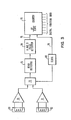
- FIG. 3 A simplified block diagram of one form of circuitry required to alternately switch elements 50, 52 for use with the present servo pattern is illustrated in Fig. 3.
- the signals from blocks A and B of segments 44 and 45 are read by elements 50 and 52, respectively, and amplified by preamplifiers 70, 71.
- a switching circuitry 72 which is supplied with a clock pulse from clock 80, alternately connects the outputs of preamplifiers 70, 71 to a read detector 73 which receives the servo signals.
- the output of read detector 73 is supplied to pulse detector circuitry 74 which supplies the signal on output line 75 indicative of each servo pulse detected. Line 75 is supplied to the input of an up/down counter 76.
- Counter 76 is started at the beginning of a servo sector by a clock signal on input line 78 from clock 80. Assuming that the element 50 is positioned over the center line 67 of the data track 60 as shown in Fig. 2, counter 76 begins counting up as the A block pulses are encountered. As soon as block B pulses of segment 44 are encountered, counter 76 is reversed and begins counting down. After blocks A and B of segment 44 have passed under element 50, the count in the up/down counter 76 provides a digital PES to the servo system to control the radial position of the elements 50, 52 for data track following. When both blocks A and B of segment 44 have passed under element 50, counter 76 is stopped.
- clock 80 switches element 52 into the circuit as the active element for reading the servo signals. This procedure is continued as the elements 50, 52 are alternately switched to read servo signals from the respective servo segments in their respective data tracks.
- the use of a head having N elements with the servo pattern of the present invention would result in a surface area for the servo pattern which occupied a fraction equal to only 1/N of the surface area for the conventional sector servo.
- the angle p in Fig. 2 of this invention does not have to be an integer fraction or multiple of the angle 6 in Fig. 1, since the area allocated to servo information and the servo signal sample rate for a given control system can be selected to any desired and appropriate values.
- the servo pattern of the present invention will function with various combinations of elements in the multiple element head.
- all of the elements could be read/write elements, or a combination of read only and read/write, since data can be written by one of the elements while another of the elements is reading servo signals.
Landscapes
- Engineering & Computer Science (AREA)
- Signal Processing (AREA)
- Moving Of The Head To Find And Align With The Track (AREA)
Applications Claiming Priority (2)
| Application Number | Priority Date | Filing Date | Title |
|---|---|---|---|
| US06/644,244 US4575775A (en) | 1984-08-27 | 1984-08-27 | Magnetic recording disk having a sector servo pattern for use with a multiple element head |
| US644244 | 1984-08-27 |
Publications (3)
| Publication Number | Publication Date |
|---|---|
| EP0173844A2 true EP0173844A2 (de) | 1986-03-12 |
| EP0173844A3 EP0173844A3 (en) | 1987-05-06 |
| EP0173844B1 EP0173844B1 (de) | 1990-06-27 |
Family
ID=24584064
Family Applications (1)
| Application Number | Title | Priority Date | Filing Date |
|---|---|---|---|
| EP85109184A Expired EP0173844B1 (de) | 1984-08-27 | 1985-07-23 | Servosystem zur Magnetkopfausrichtung für eine Magnetplattenvorrichtung mit einem Mehrspur-Magnetkopf und Verfahren zu dessen Anwendung |
Country Status (4)
| Country | Link |
|---|---|
| US (1) | US4575775A (de) |
| EP (1) | EP0173844B1 (de) |
| JP (1) | JPS6159678A (de) |
| DE (1) | DE3578471D1 (de) |
Cited By (5)
| Publication number | Priority date | Publication date | Assignee | Title |
|---|---|---|---|---|
| EP0231103A2 (de) * | 1986-01-23 | 1987-08-05 | Nippon Telegraph And Telephone Corporation | Verfahren zum Positionieren eines Wandlerkopfes |
| EP0249995A1 (de) * | 1986-06-19 | 1987-12-23 | Nec Corporation | Kopfpositioniervorrichtung für Geräte für flexible Platten |
| EP0275078A2 (de) * | 1987-01-13 | 1988-07-20 | Nec Corporation | Spurverfolgung-Kontrollsystem für magnetische Platteneinheit |
| EP0250138B1 (de) * | 1986-06-16 | 1992-09-09 | Sony Corporation | Servosystem für ein Gerät mit starren Platten |
| EP0511862A2 (de) * | 1991-04-30 | 1992-11-04 | Fujitsu Limited | Magnetplatteneinheit |
Families Citing this family (18)
| Publication number | Priority date | Publication date | Assignee | Title |
|---|---|---|---|---|
| US4796125A (en) * | 1987-08-10 | 1989-01-03 | Eastman Kodak Company | Optimizing the positioning of a pair of magnetic heads relative to spaced tracks on magnetic tape |
| US5001579A (en) * | 1988-05-27 | 1991-03-19 | Eastman Kodak Company | Method and apparatus for centering a transducer over a recorded track on a rotary storage medium |
| US5257149A (en) * | 1991-02-13 | 1993-10-26 | Seagate Technology, Inc. | Disc drive with offset address field |
| JP2625609B2 (ja) * | 1991-07-10 | 1997-07-02 | インターナショナル・ビジネス・マシーンズ・コーポレイション | ディスク記憶装置 |
| US5369535A (en) * | 1992-03-25 | 1994-11-29 | International Business Machines Corporation | Fixed block architecture disk file with improved position identification and error handling |
| US5448430A (en) * | 1993-08-05 | 1995-09-05 | International Business Machines Corporation | Track following servo demodulation |
| MY112118A (en) * | 1993-12-23 | 2001-04-30 | Hitachi Global Storage Tech Netherlands B V | System and method for skip-sector mapping in a data recording disk drive. |
| US5523903A (en) * | 1993-12-23 | 1996-06-04 | International Business Machines Corporation | Sector architecture for fixed block disk drive |
| US5587850A (en) * | 1994-08-26 | 1996-12-24 | Quantum Corporation | Data track pattern including embedded servo sectors for magneto-resistive read/inductive write head structure for a disk drive |
| US5760993A (en) * | 1995-12-14 | 1998-06-02 | International Business Machines Corporation | Information storage device with an odd number of track sequences in a zone |
| US6104562A (en) * | 1997-04-03 | 2000-08-15 | International Business Machines Corporation | Multiple element transducer for magnetic recording |
| US6567233B1 (en) | 1998-11-20 | 2003-05-20 | Cirrus Logic, Inc. | 4-D shock-sensing for hard-disk drives |
| US6552405B2 (en) | 2000-07-27 | 2003-04-22 | Kyocera Corporation | Photoelectric conversion device and manufacturing method thereof |
| US8203800B2 (en) * | 2009-03-05 | 2012-06-19 | Western Digital (Fremont), Llc | Servo design in data storage media |
| US8711517B2 (en) | 2012-04-27 | 2014-04-29 | Seagate Technology Llc | Two dimensional magnetic sensor immune to skew angle misalignment |
| US9147431B2 (en) | 2013-08-06 | 2015-09-29 | Seagate Technology Llc | Multi-sensor data transducer |
| WO2015048677A1 (en) | 2013-09-30 | 2015-04-02 | Marvell World Trade Ltd. | Generating position error signal based on data tracks for magnetic data storage |
| WO2015047730A1 (en) * | 2013-09-30 | 2015-04-02 | Marvell World Trade Ltd. | Method and apparatus for determining position of multiple drive heads |
Citations (2)
| Publication number | Priority date | Publication date | Assignee | Title |
|---|---|---|---|---|
| DE1424516B2 (de) * | 1961-10-10 | 1975-10-16 | International Business Machines Corp., Armonk, N.Y. (V.St.A.) | Einrichtung zur Spurnachlaufsteuerung der Magnetköpfe eines Magnetplattenspeichers |
| DE2657266A1 (de) * | 1975-12-23 | 1977-07-07 | Ibm | Einstellvorrichtung fuer den zugriffsarm des magnetkopfes eines magnetplattenspeichers |
Family Cites Families (4)
| Publication number | Priority date | Publication date | Assignee | Title |
|---|---|---|---|---|
| US3593333A (en) * | 1969-11-26 | 1971-07-13 | Ibm | Position detection for a track following servo system |
| JPS54135520A (en) * | 1978-04-12 | 1979-10-20 | Mitsubishi Electric Corp | Magnetic disc apparatus |
| JPS5534303A (en) * | 1978-08-31 | 1980-03-10 | Fujitsu Ltd | Head positioning servo system in magnetic disc device |
| JPS5616966A (en) * | 1979-07-17 | 1981-02-18 | Fujitsu Ltd | Track passing pulse generating circuit |
-
1984
- 1984-08-27 US US06/644,244 patent/US4575775A/en not_active Expired - Fee Related
-
1985
- 1985-06-18 JP JP60130931A patent/JPS6159678A/ja active Granted
- 1985-07-23 EP EP85109184A patent/EP0173844B1/de not_active Expired
- 1985-07-23 DE DE8585109184T patent/DE3578471D1/de not_active Expired - Fee Related
Patent Citations (2)
| Publication number | Priority date | Publication date | Assignee | Title |
|---|---|---|---|---|
| DE1424516B2 (de) * | 1961-10-10 | 1975-10-16 | International Business Machines Corp., Armonk, N.Y. (V.St.A.) | Einrichtung zur Spurnachlaufsteuerung der Magnetköpfe eines Magnetplattenspeichers |
| DE2657266A1 (de) * | 1975-12-23 | 1977-07-07 | Ibm | Einstellvorrichtung fuer den zugriffsarm des magnetkopfes eines magnetplattenspeichers |
Non-Patent Citations (1)
| Title |
|---|
| IBM TECHNICAL DISCLOSURE BULLETIN, vol. 26, no. 2, July 1983, pages 850-852; D.M. JONES "Quadrature servo generation with side-by-side data heads" * |
Cited By (10)
| Publication number | Priority date | Publication date | Assignee | Title |
|---|---|---|---|---|
| EP0231103A2 (de) * | 1986-01-23 | 1987-08-05 | Nippon Telegraph And Telephone Corporation | Verfahren zum Positionieren eines Wandlerkopfes |
| EP0231103A3 (en) * | 1986-01-23 | 1988-09-14 | Nippon Telegraph And Telephone Corporation | A head positioning system |
| EP0250138B1 (de) * | 1986-06-16 | 1992-09-09 | Sony Corporation | Servosystem für ein Gerät mit starren Platten |
| EP0249995A1 (de) * | 1986-06-19 | 1987-12-23 | Nec Corporation | Kopfpositioniervorrichtung für Geräte für flexible Platten |
| EP0275078A2 (de) * | 1987-01-13 | 1988-07-20 | Nec Corporation | Spurverfolgung-Kontrollsystem für magnetische Platteneinheit |
| EP0275078A3 (en) * | 1987-01-13 | 1990-09-12 | Nec Corporation | Track-following control system for magnetic disk drive |
| EP0511862A2 (de) * | 1991-04-30 | 1992-11-04 | Fujitsu Limited | Magnetplatteneinheit |
| EP0511862A3 (en) * | 1991-04-30 | 1993-02-10 | Fujitsu Limited | Magnetic disk drive units |
| US5347410A (en) * | 1991-04-30 | 1994-09-13 | Fujitsu Limited | Sensitivity correcting circuit of servo signal detection on data surface and offset measuring circuit in magnetic disk unit |
| EP0763820A1 (de) * | 1991-04-30 | 1997-03-19 | Fujitsu Limited | Magnetplattenantrieb |
Also Published As
| Publication number | Publication date |
|---|---|
| DE3578471D1 (de) | 1990-08-02 |
| JPH0243275B2 (de) | 1990-09-27 |
| EP0173844B1 (de) | 1990-06-27 |
| US4575775A (en) | 1986-03-11 |
| EP0173844A3 (en) | 1987-05-06 |
| JPS6159678A (ja) | 1986-03-27 |
Similar Documents
| Publication | Publication Date | Title |
|---|---|---|
| US4575775A (en) | Magnetic recording disk having a sector servo pattern for use with a multiple element head | |
| EP0444191B1 (de) | Servo zur positionierung eines mehrspur-magnetkopfes in einem bidirektionalen magnetbandsystem | |
| US4811135A (en) | Tri-phase servo pattern for providing information for positioning the transducers of a magnetic disk storage drive | |
| EP0186662B1 (de) | Selbstsynchronisierte fehlerkonfigurations-abweichung | |
| US4636885A (en) | Servo system for a magnetic disk memory having spiral tracks | |
| EP0097768B1 (de) | Servo-Positioniersystem für eine magnetische Platte | |
| US4589037A (en) | Servo control system using a varying frequency servo pattern for read/write head positioning in a magnetic recording disk file | |
| US5164863A (en) | Method for writing servo patterns to a disc of a hard disc drive | |
| JPH0449187B2 (de) | ||
| US4030130A (en) | Transducer head assembly and apparatus for using same in a plural- track record disk system | |
| JP2574980B2 (ja) | データ記憶デイスク及びその形成方法並びにデータ記録デイスクフアイル | |
| EP0390601A3 (de) | Informationsaufzeichnungsmedium und Informationsaufzeichnungs/-Wiedergabemethode und -vorrichtung, die dergleichen verwendet | |
| EP0240745A2 (de) | Servotechnik für einen Plattenantrieb | |
| US5095393A (en) | Tri-phase servo pattern for providing positioning information in a magnetic disk drive | |
| KR100373879B1 (ko) | 디스크드라이브의데이터필드에대한이중식별 | |
| US4602304A (en) | Servo pattern for dedicated surface track following servo systems | |
| US5027233A (en) | Method for determining servo position data in a disk drive | |
| US4864434A (en) | Method for writing a tri-phase servo pattern which provides information for positioning the transducers of a magnetic storage device | |
| WO1997045832A1 (en) | Disc drive servo system with dual head sampling | |
| EP0250138B1 (de) | Servosystem für ein Gerät mit starren Platten | |
| JPS60193177A (ja) | 磁気ヘツド位置設定方式 | |
| CA1220270A (en) | Servo control system using a varying frequency servo pattern for read/write head positioning in a magnetic recording disk file | |
| JPH0810887Y2 (ja) | 回転記録媒体記録再生装置 | |
| JP2590125B2 (ja) | 磁気ディスク装置 | |
| JPS6356884A (ja) | デイスク装置 |
Legal Events
| Date | Code | Title | Description |
|---|---|---|---|
| PUAI | Public reference made under article 153(3) epc to a published international application that has entered the european phase |
Free format text: ORIGINAL CODE: 0009012 |
|
| AK | Designated contracting states |
Kind code of ref document: A2 Designated state(s): DE FR GB |
|
| 17P | Request for examination filed |
Effective date: 19860624 |
|
| PUAL | Search report despatched |
Free format text: ORIGINAL CODE: 0009013 |
|
| AK | Designated contracting states |
Kind code of ref document: A3 Designated state(s): DE FR GB |
|
| 17Q | First examination report despatched |
Effective date: 19881215 |
|
| GRAA | (expected) grant |
Free format text: ORIGINAL CODE: 0009210 |
|
| AK | Designated contracting states |
Kind code of ref document: B1 Designated state(s): DE FR GB |
|
| REF | Corresponds to: |
Ref document number: 3578471 Country of ref document: DE Date of ref document: 19900802 |
|
| ET | Fr: translation filed | ||
| PLBE | No opposition filed within time limit |
Free format text: ORIGINAL CODE: 0009261 |
|
| STAA | Information on the status of an ep patent application or granted ep patent |
Free format text: STATUS: NO OPPOSITION FILED WITHIN TIME LIMIT |
|
| 26N | No opposition filed | ||
| PGFP | Annual fee paid to national office [announced via postgrant information from national office to epo] |
Ref country code: GB Payment date: 19930622 Year of fee payment: 9 |
|
| PGFP | Annual fee paid to national office [announced via postgrant information from national office to epo] |
Ref country code: FR Payment date: 19930623 Year of fee payment: 9 |
|
| PGFP | Annual fee paid to national office [announced via postgrant information from national office to epo] |
Ref country code: DE Payment date: 19930726 Year of fee payment: 9 |
|
| PG25 | Lapsed in a contracting state [announced via postgrant information from national office to epo] |
Ref country code: GB Effective date: 19940723 |
|
| GBPC | Gb: european patent ceased through non-payment of renewal fee |
Effective date: 19940723 |
|
| PG25 | Lapsed in a contracting state [announced via postgrant information from national office to epo] |
Ref country code: FR Effective date: 19950331 |
|
| PG25 | Lapsed in a contracting state [announced via postgrant information from national office to epo] |
Ref country code: DE Effective date: 19950401 |
|
| REG | Reference to a national code |
Ref country code: FR Ref legal event code: ST |