EP0173658A2 - Bremsbacke für Scheibenbremsen - Google Patents
Bremsbacke für Scheibenbremsen Download PDFInfo
- Publication number
- EP0173658A2 EP0173658A2 EP85850209A EP85850209A EP0173658A2 EP 0173658 A2 EP0173658 A2 EP 0173658A2 EP 85850209 A EP85850209 A EP 85850209A EP 85850209 A EP85850209 A EP 85850209A EP 0173658 A2 EP0173658 A2 EP 0173658A2
- Authority
- EP
- European Patent Office
- Prior art keywords
- brake
- brake pad
- balancing chamber
- pressing force
- support means
- Prior art date
- Legal status (The legal status is an assumption and is not a legal conclusion. Google has not performed a legal analysis and makes no representation as to the accuracy of the status listed.)
- Withdrawn
Links
- 238000003825 pressing Methods 0.000 claims abstract description 20
- 239000007788 liquid Substances 0.000 claims abstract description 9
- 238000001816 cooling Methods 0.000 claims description 14
- 230000001105 regulatory effect Effects 0.000 claims description 5
- 230000002093 peripheral effect Effects 0.000 claims description 2
- 230000000694 effects Effects 0.000 description 1
- 239000000463 material Substances 0.000 description 1
- 238000000034 method Methods 0.000 description 1
- 238000009827 uniform distribution Methods 0.000 description 1
Images


Classifications
-
- F—MECHANICAL ENGINEERING; LIGHTING; HEATING; WEAPONS; BLASTING
- F16—ENGINEERING ELEMENTS AND UNITS; GENERAL MEASURES FOR PRODUCING AND MAINTAINING EFFECTIVE FUNCTIONING OF MACHINES OR INSTALLATIONS; THERMAL INSULATION IN GENERAL
- F16D—COUPLINGS FOR TRANSMITTING ROTATION; CLUTCHES; BRAKES
- F16D65/00—Parts or details
- F16D65/78—Features relating to cooling
- F16D65/84—Features relating to cooling for disc brakes
- F16D65/853—Features relating to cooling for disc brakes with closed cooling system
-
- F—MECHANICAL ENGINEERING; LIGHTING; HEATING; WEAPONS; BLASTING
- F16—ENGINEERING ELEMENTS AND UNITS; GENERAL MEASURES FOR PRODUCING AND MAINTAINING EFFECTIVE FUNCTIONING OF MACHINES OR INSTALLATIONS; THERMAL INSULATION IN GENERAL
- F16D—COUPLINGS FOR TRANSMITTING ROTATION; CLUTCHES; BRAKES
- F16D65/00—Parts or details
- F16D65/02—Braking members; Mounting thereof
- F16D65/04—Bands, shoes or pads; Pivots or supporting members therefor
- F16D65/092—Bands, shoes or pads; Pivots or supporting members therefor for axially-engaging brakes, e.g. disc brakes
-
- F—MECHANICAL ENGINEERING; LIGHTING; HEATING; WEAPONS; BLASTING
- F16—ENGINEERING ELEMENTS AND UNITS; GENERAL MEASURES FOR PRODUCING AND MAINTAINING EFFECTIVE FUNCTIONING OF MACHINES OR INSTALLATIONS; THERMAL INSULATION IN GENERAL
- F16D—COUPLINGS FOR TRANSMITTING ROTATION; CLUTCHES; BRAKES
- F16D65/00—Parts or details
- F16D65/38—Slack adjusters
- F16D65/72—Slack adjusters hydraulic
-
- F—MECHANICAL ENGINEERING; LIGHTING; HEATING; WEAPONS; BLASTING
- F16—ENGINEERING ELEMENTS AND UNITS; GENERAL MEASURES FOR PRODUCING AND MAINTAINING EFFECTIVE FUNCTIONING OF MACHINES OR INSTALLATIONS; THERMAL INSULATION IN GENERAL
- F16D—COUPLINGS FOR TRANSMITTING ROTATION; CLUTCHES; BRAKES
- F16D65/00—Parts or details
- F16D65/78—Features relating to cooling
- F16D2065/784—Features relating to cooling the coolant not being in direct contact with the braking surface
-
- F—MECHANICAL ENGINEERING; LIGHTING; HEATING; WEAPONS; BLASTING
- F16—ENGINEERING ELEMENTS AND UNITS; GENERAL MEASURES FOR PRODUCING AND MAINTAINING EFFECTIVE FUNCTIONING OF MACHINES OR INSTALLATIONS; THERMAL INSULATION IN GENERAL
- F16D—COUPLINGS FOR TRANSMITTING ROTATION; CLUTCHES; BRAKES
- F16D2125/00—Components of actuators
- F16D2125/02—Fluid-pressure mechanisms
- F16D2125/10—Plural pistons interacting by fluid pressure, e.g. hydraulic force amplifiers using different sized pistons
Definitions
- the present invention relates to a brake pad for a friction brake of the disk type, with a brake lining mounted on a support means, where the lining can be pressed against a brake disk with the aid of the support means, which carries a centrally placed pressure distributor for translating pressing force to the brake disk.
- a further reason for having good surface engagement between disk and lining is that conducting heat away can thus be made more efficient. This is particularly important when it is a question of large braking power for long periods. For example, in heavy off-shore winches it may be a matter of providing braking power in the region of 4 MW for as long as half an hour.
- a still further factor that increases the need of good surface engagement between disk and lining is the desire to be able to utilise metallic liners, which have better wear resistance, but less resilience than earlier types of brake lining. Due to their poorer resilience, metallic liners have more trouble in adjusting to deformations in the brake pad.
- the object of the present invention is to provide an improved brake pad that permits giving it large dimensions, with good surface engagement and controlled surface pressure between brake disk and lining.
- the support means including a first and a second part, between which a liquid-filled balancing chamber is arranged, and by force translation between the first and second parts being intended to take place correspondingly via the liquid in the balancing chamber, whereby good surface engagement between brake disk and lining is enabled even for a large pressing force and large extension of the brake pad.
- first and second parts preferably of the O ring type, for defining the balancing chamber, this seal being adapted for being compressed should there be relative movement towards each other of the first and second parts along the line of action of the pressing force. It is further suitable to connect a spacing means for regulating the axial extension of the balancing chamber.
- the entire brake lining may have surface engagement against the brake disk that is better and more uniform than it was possible to achieve before with large brake pads.
- a braking apparatus 1 illustrated in Figure 1 there are two brake pads 3 and 4, executed according to the invention, one on either side of a brake disk 2 and acting counter to each other.
- the pad 4 is only indicated by chain-dotted lines since it is of the same implementation as the pad 3.
- the latter is carried via a pressure distributor 5 by a holder 6 supplying braking force, and can thus be pressed against the brake disk 2.
- a brake lining 7 for engagement with the brake disk 2, the lining being carried by a support means 8, in which there are included a first part 9 and a second part 10, these parts having arranged between them a liquid-filled balancing chamber 11.
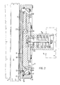
- FIG. 2 An advantageous variant of the invention is illustrated in Figure 2.
- a lining 7 is mounted on a support means 8 comprising a first and a second part 9 and 10, between which there is a balancing chamber 11.
- a seal 12 In the peripheral region between the first part 9 and the second part 10 there is a seal 12, preferably of the 0 ring type, which defines the balancing chamber 11 laterally.
- This seal 12 allows mutual movement between the parts 9 and 10 in the direction of pressure application on the pad 3.
- Pressurised medium may be supplied to the chamber 11 via an inlet 13 arranged in the second part 10, the inlet suitably being provided with a constriction 14.
- an outlet 15 for the balancing chamber is arranged in the second part 10, this outlet being equipped with a spacing regulator 16 for regulating the axial extension of the chamber 11.
- the first part 9 includes an attachment plate 17 for the brake lining, and an intermediate plate 18 situated on the inside of the plate 17 to form a wall for the balancing chamber 11.
- the attachment plate 17 is joined to a frame 19 and is sealed against it by a seal 20.
- the frame 19 is sealed via a seal 21 against the second part 10 arranged in it, such that the part 10 has no-play axial movement in the frame 19.
- the first part 9 is provided with cooling ducts 22 in communication with an inlet 23 arranged in the second part 10, and an outlet 24 also arranged in this part.
- the cooling ducts are suitably formed as grooves in the surface of the lining attachment plate 17 facing towards the intermediate plate 18.
- the implementation of the ducts may of course vary according to requirements.
- the pressure distributor 5 is attached to the brake pad 3 via a spherical bearing 25, which allows the pad to adjust itself to an attitude suitable for engagement against the brake disk 2, the pivoting axis of the bearing suitably being on a level with the surface of the brake lining.
- a possible embodiment of the spacing regulator 16 will be seen from Figure 5.
- a sensing body 26 thrusts into the balancing chamber 11 and is pressed against the intermediate plate 18 with the aid of a spring 27 carried by a holder 28.
- the holder bears via a spring 29 against the bottom of a recess 30 communicating with the outlet 15 in the second'part 10.
- Pressurised medium can pass. from the chamber 11 to the outlet 15 via a gap 31 between the sensing body 26 and a projecting portion of the holder 28.
- the pressure in the balancing chamber 11 and thus its axial extension also may be regulated as a function of the magnitude of the pressing force. For different such forces the chamber 11 will have somewhat varying size, i.e.
- the distance between the first part and the intermediate plate will vary, but independent of the size of the pressing force this will be balanced by the pressure in the balancing chamber. If the pressing force changes from a state where there is equilibrium between the force and the pressure in the chamber 11, the size of the gap 31 will increase for a reduction in the pressing force, which results in a drop in pressure in the chamber. On the other hand, if the pressing force increases, the gap 31 will decrease, with an increase in the chamber pressure as a result. By the bias in the spring 29 being greater than that in the spring 27, damage to the spacing regulator 16 is avoided when the sensing body 26 reaches an end position where it engages against the holder 28.
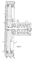
- one and the same pressurised medium may be used for cooling and for pressurising the balancing chamber 11. It is, however, quite possible to use different media for cooling and pressurising, and to provide separate inlets and outlets for them. There is nothing to prevent the cooling facility being dispensed with, which may be desirable with brakes which are only used for short durations and where there is minor need of cooling.
- An embodiment suitable for such a purpose is illustrated in Figure 6, where no cooling facility is utilised and where the intermediate plate 18 has been dispensed with.
- the balancing chamber 11 is here defined by the brake lining attachment plate 17, the seal 12 and the second part 10.
- the spacing regulator 16 has been given a substantially simplified implementation and comprises a constriction arranged around the outlet 15, the constriction being formed between the attachment plate 17 and an annular surface 32 situated between the mouth of the outlet 15 and an annular duct 33 disposed around the outlet 15 in the second part 10.
- inventions according to Figures 1, 2 and 6 are particularly suitable when the pressing force is translated via a movably mounted pressure distributor 5, which is acted on by an exterior pressure unit in the form of a brake force- supplying holder 6, as in the case with conventional disk brakes.
- a pressure distributor 5 is rigidly mounted and where the pressing force is obtained in stead by displacing the first part 9 with the aid of the pressure in the balancing chamber 11 so that the desired pressing force is obtained.
- the first part will be comparatively flexible, in any case much more flexible than the second part 10, which must not be flexible from the aspect of taking up force.
Landscapes
- Engineering & Computer Science (AREA)
- General Engineering & Computer Science (AREA)
- Mechanical Engineering (AREA)
- Braking Arrangements (AREA)
Applications Claiming Priority (2)
| Application Number | Priority Date | Filing Date | Title |
|---|---|---|---|
| SE8403412 | 1984-06-27 | ||
| SE8403412A SE446897B (sv) | 1984-06-27 | 1984-06-27 | Bromssko for friktionsbroms av skivtyp |
Publications (2)
| Publication Number | Publication Date |
|---|---|
| EP0173658A2 true EP0173658A2 (de) | 1986-03-05 |
| EP0173658A3 EP0173658A3 (de) | 1986-12-30 |
Family
ID=20356361
Family Applications (1)
| Application Number | Title | Priority Date | Filing Date |
|---|---|---|---|
| EP85850209A Withdrawn EP0173658A3 (de) | 1984-06-27 | 1985-06-18 | Bremsbacke für Scheibenbremsen |
Country Status (4)
| Country | Link |
|---|---|
| EP (1) | EP0173658A3 (de) |
| JP (1) | JPS6136525A (de) |
| NO (1) | NO852574L (de) |
| SE (1) | SE446897B (de) |
Cited By (5)
| Publication number | Priority date | Publication date | Assignee | Title |
|---|---|---|---|---|
| WO1999037939A1 (en) * | 1998-01-27 | 1999-07-29 | Skf Engineering & Research Centre B.V. | Actuator comprising flexible element, and brake calliper comprising such actuator |
| FR2853378A1 (fr) * | 2003-04-02 | 2004-10-08 | Carbone Lorraine Composants | Plaquettes de frein a disque ventilees |
| WO2018069727A1 (en) * | 2016-10-14 | 2018-04-19 | Mennie Trevor Michael | Brake control system |
| CN111365391A (zh) * | 2020-03-04 | 2020-07-03 | 涡阳县安元汽车配件有限公司 | 一种快速冷却制动器 |
| CN111779779A (zh) * | 2020-06-04 | 2020-10-16 | 吴华 | 一种汽车用刹车片间隙调整机构 |
Family Cites Families (1)
| Publication number | Priority date | Publication date | Assignee | Title |
|---|---|---|---|---|
| GB796455A (en) * | 1955-04-26 | 1958-06-11 | Roy Selden Sanford | Method and means for cooling friction elements |
-
1984
- 1984-06-27 SE SE8403412A patent/SE446897B/sv not_active IP Right Cessation
-
1985
- 1985-06-18 EP EP85850209A patent/EP0173658A3/de not_active Withdrawn
- 1985-06-26 NO NO852574A patent/NO852574L/no unknown
- 1985-06-27 JP JP13924985A patent/JPS6136525A/ja active Pending
Cited By (9)
| Publication number | Priority date | Publication date | Assignee | Title |
|---|---|---|---|---|
| WO1999037939A1 (en) * | 1998-01-27 | 1999-07-29 | Skf Engineering & Research Centre B.V. | Actuator comprising flexible element, and brake calliper comprising such actuator |
| US6598714B1 (en) | 1998-01-27 | 2003-07-29 | Sfk Engineering And Research Centre B.V. | Actuator comprising flexible element, and brake calliper comprising such actuator |
| FR2853378A1 (fr) * | 2003-04-02 | 2004-10-08 | Carbone Lorraine Composants | Plaquettes de frein a disque ventilees |
| WO2004092607A1 (fr) * | 2003-04-02 | 2004-10-28 | Carbone Lorraine Composants | Plaquettes de frein a disque ventilees |
| CN100389273C (zh) * | 2003-04-02 | 2008-05-21 | 洛林碳电路元件公司 | 通风盘式制动块 |
| WO2018069727A1 (en) * | 2016-10-14 | 2018-04-19 | Mennie Trevor Michael | Brake control system |
| US11040708B2 (en) | 2016-10-14 | 2021-06-22 | Trevor Michael Mennie | Brake control system |
| CN111365391A (zh) * | 2020-03-04 | 2020-07-03 | 涡阳县安元汽车配件有限公司 | 一种快速冷却制动器 |
| CN111779779A (zh) * | 2020-06-04 | 2020-10-16 | 吴华 | 一种汽车用刹车片间隙调整机构 |
Also Published As
| Publication number | Publication date |
|---|---|
| NO852574L (no) | 1985-12-30 |
| EP0173658A3 (de) | 1986-12-30 |
| SE8403412D0 (sv) | 1984-06-27 |
| JPS6136525A (ja) | 1986-02-21 |
| SE8403412L (sv) | 1985-12-28 |
| SE446897B (sv) | 1986-10-13 |
Similar Documents
| Publication | Publication Date | Title |
|---|---|---|
| EP0903510A3 (de) | Axiales Folienlager mit Flüssigkeitsfilm mit einer Kippsegmentstützfeder | |
| EP0173658A2 (de) | Bremsbacke für Scheibenbremsen | |
| US3384203A (en) | Disk brakes | |
| US2423882A (en) | Disk brake | |
| US4188142A (en) | Lockable swivel coupling | |
| EP0572481B1 (de) | Lastzelle und hiermit ausgerüstete bremseinrichtung | |
| GB1033802A (en) | Improvements in or relating to machine tools | |
| JP3288401B2 (ja) | 静圧テーブル装置 | |
| KR20010074806A (ko) | 디스크 브레이크 시스템 | |
| EP0455161B1 (de) | Zylinder mit radial beweglicher Stange | |
| US4079613A (en) | Press with expansible pressure cell and forming pad | |
| JPS6052329B2 (ja) | ロ−タの支承装置 | |
| AU556388B1 (en) | Journal mounted rotary joint | |
| CA2012667A1 (en) | Thickness gauge for moving sheet material | |
| US4204413A (en) | Torque limiting drive shaft assembly | |
| Baudry et al. | Influence of load and thermal distortion on the design of large thrust bearings | |
| GB1267515A (en) | Improvements in or relating to bearings | |
| ES8601423A1 (es) | Perfeccionamientos en un freno de disco para vehiculos | |
| US4521121A (en) | Air bearing | |
| GB2067249A (en) | Cooling radial face seals bearings or friction devices | |
| SE504008C2 (sv) | Roterande, regenerativ värmeväxlare där spelrummet mellan sektorplåt och rotor upprätthålls med hjälp av en gaskudde, samt sätt att driva en sådan värmeväxlare | |
| CN116175305A (zh) | 用于加工扁平工件的压盘结构、设备及其姿态控制方法 | |
| CN218152090U (zh) | 一种便于适配的耐用刹车片 | |
| US957464A (en) | Cooling attachment for wire-drawing dies. | |
| US2334119A (en) | Fluid pressure diaphragm |
Legal Events
| Date | Code | Title | Description |
|---|---|---|---|
| PUAI | Public reference made under article 153(3) epc to a published international application that has entered the european phase |
Free format text: ORIGINAL CODE: 0009012 |
|
| AK | Designated contracting states |
Kind code of ref document: A2 Designated state(s): DE FR GB SE |
|
| PUAL | Search report despatched |
Free format text: ORIGINAL CODE: 0009013 |
|
| AK | Designated contracting states |
Kind code of ref document: A3 Designated state(s): DE FR GB SE |
|
| STAA | Information on the status of an ep patent application or granted ep patent |
Free format text: STATUS: THE APPLICATION IS DEEMED TO BE WITHDRAWN |
|
| 18D | Application deemed to be withdrawn |
Effective date: 19870701 |
|
| RIN1 | Information on inventor provided before grant (corrected) |
Inventor name: HAKAN, INGVAST |