EP0173652A2 - Vorrichtung zum Schleifen von Kettensägezähnen - Google Patents
Vorrichtung zum Schleifen von Kettensägezähnen Download PDFInfo
- Publication number
- EP0173652A2 EP0173652A2 EP85830179A EP85830179A EP0173652A2 EP 0173652 A2 EP0173652 A2 EP 0173652A2 EP 85830179 A EP85830179 A EP 85830179A EP 85830179 A EP85830179 A EP 85830179A EP 0173652 A2 EP0173652 A2 EP 0173652A2
- Authority
- EP
- European Patent Office
- Prior art keywords
- grinding wheel
- casing
- action
- tooth
- chain
- Prior art date
- Legal status (The legal status is an assumption and is not a legal conclusion. Google has not performed a legal analysis and makes no representation as to the accuracy of the status listed.)
- Withdrawn
Links
Images

Classifications
-
- B—PERFORMING OPERATIONS; TRANSPORTING
- B23—MACHINE TOOLS; METAL-WORKING NOT OTHERWISE PROVIDED FOR
- B23D—PLANING; SLOTTING; SHEARING; BROACHING; SAWING; FILING; SCRAPING; LIKE OPERATIONS FOR WORKING METAL BY REMOVING MATERIAL, NOT OTHERWISE PROVIDED FOR
- B23D63/00—Dressing the tools of sawing machines or sawing devices for use in cutting any kind of material, e.g. in the manufacture of sawing tools
- B23D63/08—Sharpening the cutting edges of saw teeth
- B23D63/16—Sharpening the cutting edges of saw teeth of chain saws
- B23D63/166—Sharpening the cutting edges of saw teeth of chain saws without removal of the saw chain from the guide bar
Definitions
- the invention relates to a device for grinding, according with the suitable angles and dephts, the tooths of a chain saw, which, as known, are sequence-disposed on a chain which winds a bearing saw blade, able to permit the rotation of the chain under the motoring over effect of an internal combustion engine.
- the tooths In chain saws, the tooths allows to cut wooden materials by removing shavings with defined thiknesses; for a good functioning of the chain saw it's necessary that all the tooths are well grinded according with predetermined angles and dephts; with use, the grinding runs low so it has to be reset to avoid a bad functioning of the chain saw and a further damaging of the tooths consuming a considerable quantity of energy.
- grinder To reset the tooths grinding, grinder are used which are mounted on a workbench,therefore, they are heavy and bulky; they operate on a chain removed from the chain saw and have the disadvantage of not to be portable.
- Portable device like saw files or candle grinding wheels which grind the tooths.
- the first ones are used in an empiric way so the operator has to be very expert and the operation requires many time.
- the second ones are subjected to wear because of their particular geometry, therefore, each grinding wheel can be used only for a small number of chains.
- the invention as claimed is intended to remedy these drawbacks. It solves the problem of how to create a device for grinding chain saw tooths or similar cutting machines. By using such a device the following advantages are achieved: the grinding of the tooths is made by a disk grinding wheel, whose average life is longer than that of candle grinding wheels; the angle and de- pht precision is guaranteed for a numberous series of chains to grind.
- the advantages offered by the invention are mainly that the use of a disk grinding wheel allows, in addition to the already said uniformity in work during time, a very easy use; such a device is portable, appliable to the not-removed chain of a chain saw; it can be used where- ever it is present an energy source for a motor which rotates the grinding wheel.
- the device is extremely durable.
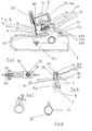
- the figures show a device for grinding chain saw tooths comprising a structure 1 suitable to be fixed on a saw blade 2 of a chain saw 3; said structure 1 comprising a supporting element for a casing 4 able to house an electric motor with a shaft splined on an axis of rotation of a disk grinding wheel 5 suitable to go in contact with a tooth 6 of a chain of.said chain saw 3 to reset the correct cutting angle.
- the structure 1 is suitable to be disposed astride said saw blade 2, comprising, as it can be noted in Fig. 6, a jaw 7 fitted with an engaging screw 8 for said saw blade 2; said screw 8 permitting to structure 1 to remain fixed relative to the saw blade 2 cooperating with abutment structures 8a.
- the structure 1 supports a first and a second flexible sheet elastic clamps 9a and 9b, fitted with, respectively, a first and a second adjusting screw 10a and 10b of the elastic preload of said clamps 9a and 9b to constrain the tooth 6 relative to the structure 1 to avoid the consequences of the transversal stresses given by the grinding wheel 5.
- a third and a fourth positioning screw define the position of the sheet 9 relative to structure 1.
- a metallic sheet bar 12 defines, rightwards, the position of each tooth 6; said bar has a first bent left end 12a to avoid the rightwards translation of the tooth 6 and to favour the positioning of a subsequent tooth, which, by sliding, allows the rising of said end 12a.
- said bar 12 On a second end 12b, said bar 12 is fitted with a slot - on which engages a fixing and adjusting screw 13 of the position of said bar 12.
- Said structure 1 supports a pin 14 (Fig. 6) able to permit the rotation of a bush 15 integral with a pin 16 suitable to be inserted in a bushing 17 inside of which a torsion spring 18 is arranged able to oppose the relative rotation of the bushing 17 with respect to the pin 16.
- An elastic ring is inserted in a groove 20 of said pin 16 to prevent the translation of the said pin inside the bushing 17.
- annular surface 21 which has a splined zone 22 with radial splines relative to the centre of said surface 21; the splines of the zone 22 cooperate with similar splines made in a front surface 23 of said bush 15 to prevent not required rotations when using the device and to arrange at a suitable angle the bushing 17 relative to pin 14.
- Said screw 24 supports a knob 26 with a knurled side surface 27 which, opportunely thighten, gives to bushing 17 a force necessary and sufficient to prevent the rotations between said splines.
- the thrust of the screw 24 is given to bushing 17 by the pressure contact of two surfaces 28a and 28b, respectively, belonging to bush 15 and knob 26.
- the structure 1 For a visual positioning of bush 15 relative to pin 14, the structure 1 has a reference graduated zone 29 and the bush 15 has a vertical nick 30 allowing the angular positioning of bush 15 relative to pin 14 to obtain a subsequent correct functioning of the device.
- the casing 4 is rotated around pin 16 by insisting on a handle 31 situated as protuberance of the same casing 4 in its upper part against the action of a return spring 18.
- two limit stop screws 32a and 32b are provided inserted in respective holes 33a and 33b made in, respectively, two lugs 34a and 34b of the structure 1 for engaging pin 16.
- the ends of said screws 32a and 32b cooperate with a rib 35 disposed on a symmetry plane in said casing 4 and suitable to abut with a face 36a on screw 32a to define the maximum leftwards angular excursion of casing 4 and with a face 36b on screw 32b to define the maximum rightwards angular excursion of casing 4.
- the casing 4 houses an electric motor, not shown, which is correctely and steadily positioned inside said casing 4 by known means, not shown, and by an elastic ring 37 made in the body of said casing 4 and suitable to be closed by a closing screw 38 housed in a hole 39.
- Said motor has a shaft 40 on which the disk grinding wheel 5 is splined,in known way and means not shown; said disk grinding wheel 5 is sheltered, in its upper part, by a sump 41 to prevent damages, due to sparks, to the operator.
- the first operation to do is the fitting up of the device on the saw blade 2, fitting up which doesn't require the removal of the chain from the chain saw 3; to do that, it is necessary to opportunely position the device so that the clamps 9a and 9b are in a position such as to cover the same chain to elastically engage it under the action of the two screws 10a and 10b.
- the sctructural element allowing the steady positioning of structure 1 relative to the saw blade 2, is the screw 8.
- the bar 12 is disposed, after having manoeuve- red on screw 13, in such a way that the end 12a of the same bar defines the working position for each tooth.
- the motor is runned and, in consequence, the grinding wheel 5 is runned too; with a manual thrust on the handle 31 the casing 4 is putted downwards in such a way that the grinding wheel 5 disposes in the position shown in Fig. 3, that is in contact with the cutting contour of the tooths.
- the invention can be subjected to modifications not affeting its essence.
- the structure 1 can be constitued by an essentially closed tubular shaped bearing zone able to wholly house said saw blade 2 and fitted with previously mentioned engaging means for the same saw blade.
- the bushing 17 can be fitted with a milling,parallel to its own symmetry axis,to precision house an U-shaped structure whose bent ends are turned towards said pin 16; two pins are fixed on this latter able to engage the bent -ends of the spring 18; two pins delimiting the position of structure 1.
Landscapes
- Engineering & Computer Science (AREA)
- Mechanical Engineering (AREA)
- Finish Polishing, Edge Sharpening, And Grinding By Specific Grinding Devices (AREA)
- Constituent Portions Of Griding Lathes, Driving, Sensing And Control (AREA)
- Mechanical Treatment Of Semiconductor (AREA)
- Grinding Of Cylindrical And Plane Surfaces (AREA)
Applications Claiming Priority (2)
| Application Number | Priority Date | Filing Date | Title |
|---|---|---|---|
| IT8403524A IT1212183B (it) | 1984-07-12 | 1984-07-12 | Dispositivo atto ad affilare denti di motoseghe |
| IT352484 | 1984-07-12 |
Publications (2)
| Publication Number | Publication Date |
|---|---|
| EP0173652A2 true EP0173652A2 (de) | 1986-03-05 |
| EP0173652A3 EP0173652A3 (de) | 1987-07-15 |
Family
ID=11109009
Family Applications (1)
| Application Number | Title | Priority Date | Filing Date |
|---|---|---|---|
| EP85830179A Withdrawn EP0173652A3 (de) | 1984-07-12 | 1985-07-09 | Vorrichtung zum Schleifen von Kettensägezähnen |
Country Status (7)
| Country | Link |
|---|---|
| US (1) | US4658677A (de) |
| EP (1) | EP0173652A3 (de) |
| JP (1) | JPS6156819A (de) |
| CA (1) | CA1234984A (de) |
| ES (1) | ES8607087A1 (de) |
| IT (1) | IT1212183B (de) |
| YU (1) | YU44776B (de) |
Cited By (1)
| Publication number | Priority date | Publication date | Assignee | Title |
|---|---|---|---|---|
| GB2337713A (en) * | 1998-05-27 | 1999-12-01 | Christopher Lehan | Sharpening chain saws. |
Families Citing this family (7)
| Publication number | Priority date | Publication date | Assignee | Title |
|---|---|---|---|---|
| JPH0627015U (ja) * | 1992-09-09 | 1994-04-12 | 伸治 石澤 | チェンソーのチェンの刃を研磨する目立て機 |
| SI21497A (sl) * | 2003-12-01 | 2004-12-31 | Drago �ENDAK | Naprava za ostrenje zob verižne žage |
| US10265788B2 (en) * | 2015-11-30 | 2019-04-23 | Scott D. Lynn | Chainsaw sharpening device, system, and method |
| IT201800004034A1 (it) * | 2018-03-28 | 2019-09-28 | Tecomec Srl | Affilatrice portatile |
| WO2020002750A1 (en) * | 2018-06-29 | 2020-01-02 | Fomatec Oy | Method and apparatus for sharpening a saw chain |
| CN109014407B (zh) * | 2018-09-26 | 2024-01-16 | 高海鑫 | 一种锯片磨齿机 |
| USD969889S1 (en) | 2019-12-13 | 2022-11-15 | Tecomec S.R.L. | Sharpening machine |
Family Cites Families (11)
| Publication number | Priority date | Publication date | Assignee | Title |
|---|---|---|---|---|
| US2372699A (en) * | 1941-07-18 | 1945-04-03 | Delta Mfg Co | Cutting machine |
| US2410828A (en) * | 1943-11-19 | 1946-11-12 | Jr Anders R Lofstrand | Chain saw sharpener |
| US2792724A (en) * | 1956-02-06 | 1957-05-21 | Durall Hugh | Chain saw sharpener |
| CH397384A (de) * | 1962-07-26 | 1965-08-15 | Moor Hans | Schärfapparat zum Schleifen von Hobelzahnketten und deren Tiefenbegrenzer |
| FR1382923A (fr) * | 1963-03-28 | 1964-12-24 | Dispositif pour affûter les scies à ruban, à moteur, articulées à la manière d'une chaîne | |
| US3768341A (en) * | 1971-12-17 | 1973-10-30 | J Fitzpatrick | Chain saw sharpening device |
| DE2202757A1 (de) * | 1972-01-21 | 1973-07-26 | Stihl Maschf Andreas | Spannvorrichtung fuer fuehrungsschienen von motorkettensaegen |
| US3877324A (en) * | 1974-04-29 | 1975-04-15 | Elmer Ray Silvey | Grinder for saw bar mounted saw chain |
| JPS5518381A (en) * | 1978-07-28 | 1980-02-08 | Minami Kogyo Kk | Polisher for chain saw blade |
| US4319502A (en) * | 1979-10-01 | 1982-03-16 | Smith Victor W | Portable saw chain sharpener |
| AU7967982A (en) * | 1981-02-06 | 1982-08-12 | Turner, J.P. | Chain-saw sharpening device |
-
1984
- 1984-07-12 IT IT8403524A patent/IT1212183B/it active
-
1985
- 1985-06-28 CA CA000485860A patent/CA1234984A/en not_active Expired
- 1985-07-09 US US06/753,038 patent/US4658677A/en not_active Expired - Fee Related
- 1985-07-09 EP EP85830179A patent/EP0173652A3/de not_active Withdrawn
- 1985-07-11 JP JP60151479A patent/JPS6156819A/ja active Pending
- 1985-07-11 YU YU1150/85A patent/YU44776B/xx unknown
- 1985-07-11 ES ES545066A patent/ES8607087A1/es not_active Expired
Cited By (2)
| Publication number | Priority date | Publication date | Assignee | Title |
|---|---|---|---|---|
| GB2337713A (en) * | 1998-05-27 | 1999-12-01 | Christopher Lehan | Sharpening chain saws. |
| GB2337713B (en) * | 1998-05-27 | 2002-12-18 | Christopher Lehan | Sharpening device |
Also Published As
| Publication number | Publication date |
|---|---|
| US4658677A (en) | 1987-04-21 |
| JPS6156819A (ja) | 1986-03-22 |
| IT8403524A0 (it) | 1984-07-12 |
| ES8607087A1 (es) | 1986-06-01 |
| IT1212183B (it) | 1989-11-22 |
| EP0173652A3 (de) | 1987-07-15 |
| CA1234984A (en) | 1988-04-12 |
| YU115085A (en) | 1989-10-31 |
| YU44776B (en) | 1991-02-28 |
| ES545066A0 (es) | 1986-06-01 |
Similar Documents
| Publication | Publication Date | Title |
|---|---|---|
| US4545121A (en) | Hand-held power tool with circular-disk-shaped tool | |
| EP0173652A2 (de) | Vorrichtung zum Schleifen von Kettensägezähnen | |
| EP2699384B1 (de) | Schärfungsvorrichtung für eine schneidklinge | |
| EP3173188A1 (de) | Tragbare, handgeführte trennschleifmaschine | |
| EP3380273A1 (de) | Tragbare, handgeführte trennschleifmaschine | |
| CN110873150A (zh) | 具有凸轮的可调冲程装置 | |
| JP2007522953A (ja) | 切断チェーン用グラインダーと研磨の方法 | |
| US5518441A (en) | Device for manual assembly and removal of working discs in manual tools for machining surfaces | |
| US6846231B2 (en) | Removable sharpening attachment for a rotary hand tool | |
| US10272534B2 (en) | Grinding machine with movable water trough | |
| EP0202913A2 (de) | Doppelzweck-Schleifmaschine | |
| EP0214943A2 (de) | Einspannvorrichtung zum Schleifen von Messern | |
| US20020061719A1 (en) | Electric chain saw sharpening machine | |
| US7210986B2 (en) | System and method for duplicating keys | |
| US2742799A (en) | Circular saw grinding fixture | |
| US5027559A (en) | Sharpening unit for leather splitting machines | |
| KR101821509B1 (ko) | 연마기 | |
| US2999402A (en) | Tool for sharpening ice skates | |
| CN219403907U (zh) | 一种可对中定位的砂轮轮廓修整器 | |
| US12005543B2 (en) | Radius adjustment apparatus for use with a grinding machine | |
| US1813825A (en) | Machine for grinding saws | |
| CN222589230U (zh) | 一种非标零配件加工用磨销装置 | |
| US3140569A (en) | Chuck for a valve grinder | |
| US2834163A (en) | Work holding device | |
| US20250144761A1 (en) | A grinding angle setting device, a grinding system and a method of setting a grinding angle |
Legal Events
| Date | Code | Title | Description |
|---|---|---|---|
| PUAI | Public reference made under article 153(3) epc to a published international application that has entered the european phase |
Free format text: ORIGINAL CODE: 0009012 |
|
| AK | Designated contracting states |
Kind code of ref document: A2 Designated state(s): AT BE CH DE FR GB LI LU NL SE |
|
| PUAL | Search report despatched |
Free format text: ORIGINAL CODE: 0009013 |
|
| AK | Designated contracting states |
Kind code of ref document: A3 Designated state(s): AT BE CH DE FR GB LI LU NL SE |
|
| 17P | Request for examination filed |
Effective date: 19880115 |
|
| 17Q | First examination report despatched |
Effective date: 19890102 |
|
| STAA | Information on the status of an ep patent application or granted ep patent |
Free format text: STATUS: THE APPLICATION IS DEEMED TO BE WITHDRAWN |
|
| 18D | Application deemed to be withdrawn |
Effective date: 19910201 |
|
| RIN1 | Information on inventor provided before grant (corrected) |
Inventor name: LUSETTI, GIORGIO |