EP0173333B1 - Extrudierverfahren und Extrudierdüse mit zentralem Luftstrom - Google Patents
Extrudierverfahren und Extrudierdüse mit zentralem Luftstrom Download PDFInfo
- Publication number
- EP0173333B1 EP0173333B1 EP85110883A EP85110883A EP0173333B1 EP 0173333 B1 EP0173333 B1 EP 0173333B1 EP 85110883 A EP85110883 A EP 85110883A EP 85110883 A EP85110883 A EP 85110883A EP 0173333 B1 EP0173333 B1 EP 0173333B1
- Authority
- EP
- European Patent Office
- Prior art keywords
- thermoplastic material
- extrusion
- thermoplastic
- opening
- high velocity
- Prior art date
- Legal status (The legal status is an assumption and is not a legal conclusion. Google has not performed a legal analysis and makes no representation as to the accuracy of the status listed.)
- Expired - Lifetime
Links
- 238000001125 extrusion Methods 0.000 title claims description 78
- 238000000034 method Methods 0.000 title claims description 30
- 239000012815 thermoplastic material Substances 0.000 claims description 130
- 229920001169 thermoplastic Polymers 0.000 claims description 38
- 239000004416 thermosoftening plastic Substances 0.000 claims description 37
- 239000000835 fiber Substances 0.000 claims description 31
- 239000000654 additive Substances 0.000 claims description 20
- 230000000996 additive effect Effects 0.000 claims description 20
- 239000000463 material Substances 0.000 claims description 20
- 238000010791 quenching Methods 0.000 claims description 9
- 230000000171 quenching effect Effects 0.000 claims description 9
- 239000007788 liquid Substances 0.000 claims description 4
- 230000000704 physical effect Effects 0.000 claims description 4
- 229920001131 Pulp (paper) Polymers 0.000 claims description 2
- 239000000155 melt Substances 0.000 claims description 2
- 238000010438 heat treatment Methods 0.000 claims 4
- 239000007789 gas Substances 0.000 description 41
- 239000003570 air Substances 0.000 description 24
- 239000011261 inert gas Substances 0.000 description 20
- 229920000642 polymer Polymers 0.000 description 12
- -1 polyethylene Polymers 0.000 description 9
- 230000002238 attenuated effect Effects 0.000 description 6
- 230000015572 biosynthetic process Effects 0.000 description 6
- 238000007664 blowing Methods 0.000 description 6
- 229920001410 Microfiber Polymers 0.000 description 5
- 239000003658 microfiber Substances 0.000 description 5
- 239000004698 Polyethylene Substances 0.000 description 3
- 238000002844 melting Methods 0.000 description 3
- 230000008018 melting Effects 0.000 description 3
- 229920000573 polyethylene Polymers 0.000 description 3
- 229920000098 polyolefin Polymers 0.000 description 3
- 239000004743 Polypropylene Substances 0.000 description 2
- 239000004793 Polystyrene Substances 0.000 description 2
- 230000015556 catabolic process Effects 0.000 description 2
- 239000002131 composite material Substances 0.000 description 2
- 238000006731 degradation reaction Methods 0.000 description 2
- 238000009413 insulation Methods 0.000 description 2
- 238000004519 manufacturing process Methods 0.000 description 2
- 239000000203 mixture Substances 0.000 description 2
- 230000002093 peripheral effect Effects 0.000 description 2
- 229920000058 polyacrylate Polymers 0.000 description 2
- 229920001155 polypropylene Polymers 0.000 description 2
- 229920002223 polystyrene Polymers 0.000 description 2
- 239000000126 substance Substances 0.000 description 2
- 238000011144 upstream manufacturing Methods 0.000 description 2
- 229920002134 Carboxymethyl cellulose Polymers 0.000 description 1
- 240000000491 Corchorus aestuans Species 0.000 description 1
- 235000011777 Corchorus aestuans Nutrition 0.000 description 1
- 235000010862 Corchorus capsularis Nutrition 0.000 description 1
- 229920000742 Cotton Polymers 0.000 description 1
- 240000006240 Linum usitatissimum Species 0.000 description 1
- 235000004431 Linum usitatissimum Nutrition 0.000 description 1
- 229920000305 Nylon 6,10 Polymers 0.000 description 1
- 229920002302 Nylon 6,6 Polymers 0.000 description 1
- 239000004952 Polyamide Substances 0.000 description 1
- 239000012080 ambient air Substances 0.000 description 1
- 239000001768 carboxy methyl cellulose Substances 0.000 description 1
- 235000010948 carboxy methyl cellulose Nutrition 0.000 description 1
- 239000008112 carboxymethyl-cellulose Substances 0.000 description 1
- 229920002678 cellulose Polymers 0.000 description 1
- 238000004891 communication Methods 0.000 description 1
- 238000010586 diagram Methods 0.000 description 1
- 238000005553 drilling Methods 0.000 description 1
- 125000004494 ethyl ester group Chemical group 0.000 description 1
- 239000012530 fluid Substances 0.000 description 1
- 239000012943 hotmelt Substances 0.000 description 1
- 239000011810 insulating material Substances 0.000 description 1
- 239000011159 matrix material Substances 0.000 description 1
- 125000002496 methyl group Chemical group [H]C([H])([H])* 0.000 description 1
- 210000003632 microfilament Anatomy 0.000 description 1
- 239000002245 particle Substances 0.000 description 1
- 239000011236 particulate material Substances 0.000 description 1
- 229920002239 polyacrylonitrile Polymers 0.000 description 1
- 229920002647 polyamide Polymers 0.000 description 1
- 229920000728 polyester Polymers 0.000 description 1
- 229920000139 polyethylene terephthalate Polymers 0.000 description 1
- 239000005020 polyethylene terephthalate Substances 0.000 description 1
- 238000012667 polymer degradation Methods 0.000 description 1
- 229920000193 polymethacrylate Polymers 0.000 description 1
- 159000000000 sodium salts Chemical class 0.000 description 1
- 239000004094 surface-active agent Substances 0.000 description 1
- 239000010409 thin film Substances 0.000 description 1
- 229920002554 vinyl polymer Polymers 0.000 description 1
- XLYOFNOQVPJJNP-UHFFFAOYSA-N water Chemical compound O XLYOFNOQVPJJNP-UHFFFAOYSA-N 0.000 description 1
Images


Classifications
-
- D—TEXTILES; PAPER
- D01—NATURAL OR MAN-MADE THREADS OR FIBRES; SPINNING
- D01D—MECHANICAL METHODS OR APPARATUS IN THE MANUFACTURE OF ARTIFICIAL FILAMENTS, THREADS, FIBRES, BRISTLES OR RIBBONS
- D01D4/00—Spinnerette packs; Cleaning thereof
- D01D4/02—Spinnerettes
- D01D4/025—Melt-blowing or solution-blowing dies
-
- D—TEXTILES; PAPER
- D01—NATURAL OR MAN-MADE THREADS OR FIBRES; SPINNING
- D01D—MECHANICAL METHODS OR APPARATUS IN THE MANUFACTURE OF ARTIFICIAL FILAMENTS, THREADS, FIBRES, BRISTLES OR RIBBONS
- D01D4/00—Spinnerette packs; Cleaning thereof
- D01D4/02—Spinnerettes
-
- D—TEXTILES; PAPER
- D04—BRAIDING; LACE-MAKING; KNITTING; TRIMMINGS; NON-WOVEN FABRICS
- D04H—MAKING TEXTILE FABRICS, e.g. FROM FIBRES OR FILAMENTARY MATERIAL; FABRICS MADE BY SUCH PROCESSES OR APPARATUS, e.g. FELTS, NON-WOVEN FABRICS; COTTON-WOOL; WADDING ; NON-WOVEN FABRICS FROM STAPLE FIBRES, FILAMENTS OR YARNS, BONDED WITH AT LEAST ONE WEB-LIKE MATERIAL DURING THEIR CONSOLIDATION
- D04H1/00—Non-woven fabrics formed wholly or mainly of staple fibres or like relatively short fibres
- D04H1/40—Non-woven fabrics formed wholly or mainly of staple fibres or like relatively short fibres from fleeces or layers composed of fibres without existing or potential cohesive properties
- D04H1/54—Non-woven fabrics formed wholly or mainly of staple fibres or like relatively short fibres from fleeces or layers composed of fibres without existing or potential cohesive properties by welding together the fibres, e.g. by partially melting or dissolving
- D04H1/56—Non-woven fabrics formed wholly or mainly of staple fibres or like relatively short fibres from fleeces or layers composed of fibres without existing or potential cohesive properties by welding together the fibres, e.g. by partially melting or dissolving in association with fibre formation, e.g. immediately following extrusion of staple fibres
Definitions
- the present invention relates to an apparatus and a method for extruding thermoplastic fibres as outlined in the preambles of claim 1 and 24.
- the known apparatus contains a die head with a centrally disposed high velocity gas bore adapted to receive a gas stream and terminating in a circular nozzle opening for emitting the gas as a gas jet.
- the circular nozzle opening is surrounded by a second nozzle opening of annular shape adapted to emit the same gas as emitted from the central opening.
- the molten thermoplastic material is delivered to outlet openings arranged within the bore spaced from and upstream of the circular nozzle opening.
- the known method comprises the forming of thin film of the molten thermoplastic material between the gas stream and the walls of the bore before the fibres are formed between the central jet and the annular jet during escape into the quenching medium outside the die head.
- Nonwoven mats produced by these and other currently known melt blowing processes and the apparatuses used therefor employ an extruder to force a hot melt of thermoplastic material through a row of fine orifices and directly into converging high velocity streams of heated gas, usually air arranged on alternate sides of the extrusion orifices. Fibres of the thermoplastic material are attenuated within the gas stream, the fibres solidifying at a point where the temperature is low enough.
- the present invention provides the potential to at least double the throughput rate realized by currently used melt blowing processes and apparatuses used therefor.
- the apparatus and method of the present invention also permit the formation of composite webs of two or more different polymers.
- the present invention further provides enhancement of quenching of fibres or filaments formed by the method of the present invention due to the closer proximity of the fibres to the quenching air or water vapor used in the process.
- the present invention additionally provides more quiescent exit conditions for extruded thermoplastic material, resulting in less flow disturbance in the downstream region.
- the present invention also permits the entanglement of filaments or fibres in the initial shear region in which turbulence scales are smaller.
- a die head or extrusion head 10 is provided with a chamber 12 for containing a polymeric, generally a thermoplastic material.
- the thermoplastic material may be supplied to chamber 12, generally under pressure, by delivery means or devices 36 such as a supply hopper and an extruder screw or the like.
- the thermoplastic material may be rendered fluid or molten by one or more heaters 39 placed appropriately, such as surrounding the chamber 12, surrounding the hopper and/or between the hopper and the chamber.
- chamber 12 is provided with outlet passages 14 and 16 which permit the flow of molten thermoplastic material from the chamber to a plurality of thermoplastic extrusion outlets, openings or orifices 18 and 20 or a single such opening 19 located in a preferably circular die tip and arranged surrounding a centrally placed means for delivering a generally inert gas as, for example, air, at a high velocity, with an opening such as a nozzle 22 or the like from a source of inert gas 23.
- a generally inert gas as, for example, air
- the air emanating from the high velocity nozzle may be heated by a heater (not shown), appropriately placed, such as in or surrounding the source of inert gas 23 or nozzle 22 itself.
- chamber 12 may be provided with a single outlet (shown in phantom in Figure 1) which branches or forks into two or more passages.
- high velocity generally describes jets having velocities of about 91 to over 610 m/sec (about 300 to over 2,000 feet/second).
- central or "centrally”, as applied to the gas delivery means or jets, generally includes all situations in which the gas delivery means is surrounded by or arranged between thermoplastic extrusion openings or a portion thereof.
- thermoplastic extrusion opening 19 there may be as few as a single thermoplastic extrusion opening 19 surrounding or at least two thermoplastic extrusion openings 18 and 20 placed around an opening comprising the high velocity gas delivery means or air nozzle 22.
- the high velocity gas delivery means 22 has the form of an elongated opening or slot and a series or individual thermoplastic extrusion openings or slits 18 and 20 are arranged in rows on opposite sides of the gas delivery means 22 as in Figures 3a and 3b.
- the openings 18 and 20 are arranged such that their longitudinal axes form an included angle with the longitudinal axis of the high velocity gas delivery nozzle of about 30 degrees to less than about 90 degrees.
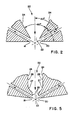
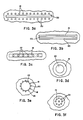
- FIG. 3a-f Some of the arrangements of the centrally placed gas jet and thermoplastic extrusion openings of the present invention, as viewed from the bottom, are shown in Figures 3a-f.
- One preferred arrangement is shown in Figure 3a in which two series of holes 18 and 20 are arranged in rows substantially parallel to and on opposite sides of nozzle 22, formed as a linear, elongated opening or slot.
- Each of the openings in series 18 may be arranged opposite to a corresponding hole in series 20.
- the holes in the two series may have a staggered or skewed relationship with respect to one another.
- Figure 3b depicts an arrangement in which two thermoplastic extrusion openings 18 and 20 take the form of elongated linear openings or slits placed parallel to and on opposite sides of the elongated linear gas nozzle or slot 22.
- the arrangement shown in Figure 3c provides for the inert gas to be emitted from capillary gas nozzles 22 arranged within an elongated slit 19 from which the polymeric material flows.
- nozzles 22 are arranged here linearly along a plane passing through the center and parallel to the elongated edges of the slit, other arrangements, such as an alternating or zigzag arrangement of the air nozzles, are also possible.
- Figure 3d illustrates an extrusion arrangement in which an inert gas nozzle 22, having a circular cross section, is arranged concentrically within a cylindrical opening so that the inner surface of the cylindrical opening and the outer surface of the inert gas nozzle form an annular extrusion opening 19.
- the central air nozzle 22 may have a diameter of up to about 51 mm (two inches).
- the embodiment shown in Figure 3e includes a plurality of thermoplastic polymer extrusion openings 18 and 20 arranged in spaced relationship to one another and to the inert gas nozzle around the circumference of the inert gas nozzle.
- Figure 3f illustrates a plurality of capillary gas nozzles 22 arranged centrally within a thermoplastic extrusion opening 19 having a circular cross section.
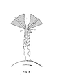
- the die head arrangement of the present invention permits molten thermoplastic material to be transferred from chamber 12 through the passages or conduits 14 and 16 to the extrusion openings 19 or 18 and 20, whereupon, as shown in Figure 4, the molten extrudate emerges and contacts the shear layers of the at least one jet of high velocity gas which is being continuously emitted in a stream from the one or more centrally placed nozzles 22.
- the shear layers are considered to be those layers or portions of the inert gas jet located in the peripheral regions of the jet.
- This arrangement results in a plurality of streams, preferably two streams, in the preferred embodiments shown in Figures 3a and 3b of molten extrudate being first attenuated in the peripheral portions or shear layers of the jet or jets, thereby forming filaments or fibers which are mixed and directed to a forming or collecting foraminous surface 37, such as a roll, (shown in Figure 8) or a moving wire placed in the vicinity of the die heads, where the fibers form a matrix or mat 38.
- a forming or collecting foraminous surface 37 such as a roll, (shown in Figure 8) or a moving wire placed in the vicinity of the die heads, where the fibers form a matrix or mat 38.
- the present invention provides the potential to more than double the throughput rate of fiber formation compared to existing processes and apparatus used therefor.
- the filaments formed by the die head of the present invention are attenuated in the shear layers of the high velocity gas stream, these filaments are closer to the air entrained from the atmosphere surrounding the apparatus and quenching becomes much more effective than conventional apparatus in which air jets converge on a centrally emitted stream of thermoplastic material.
- Figures 2 and 5 illustrate in section several configurations of the exit portion of the high velocity gas delivery nozzle 22.
- the wall sections 24 of the outlet portion of the nozzle 22 may be straight and may be arranged substantially parallel to one another, as shown in Figures 5 to 7 or may be arranged to form an included angle with respect to each other, as is shown in Figure 2.
- the included angle formed by the wall sections of the tip of the high velocity gas outlet nozzle is about 60 degrees.
- the tip of the nozzle has a slightly different configuration.
- the tip of the nozzle has a contoured or gradually curving and tapering configuration in which the outlet nozzle walls 26, which are arranged in approximately parallel relationship, taper through a gradual S-shaped configuration 27 to a more constricted nozzle tip 28 in which the walls are approximately parallel or arranged at a slight angle to one another.
- a conduit such as a tube or duct 30, may be placed concentrically within and spaced from the walls 24 of the high velocity gas delivery nozzle.
- the additive delivery conduit may take the form of a duct 30, the outlet end of which is recessed from the outer portion or exit plane 32 formed by the outer surfaces of the high velocity gas delivery nozzle.
- the additive delivery conduit may take the form of a duct 34, the outlet end of which extends from the outer portion or beyond the exit plane of the high velocity gas delivery nozzle.
- the end of the duct may also be arranged with the outlet end having a position between those shown in solid line or in phantom in Figure 6, particularly one in which the outlet end of the duct is flush with plane 32.
- a means may also be provided to move the duct between the two positions illustrated.
- the additive which is introduced into the air stream through the duct may be any gaseous, liquid (such as surfactants or encapsulated liquids), or particulate material (such as a superabsorbent material, i.e., a material capable of absorbing many times its weight of liquid, preferred being materials such as carboxymethyl cellulose and the sodium salt of a cross linked polyacrylate; wood pulp or staple fibers, as, for example, cotton, flax, silk or jute), which is intended to form part of the fibers or the finished web.
- the additive material may be fed from a source located within the extrusion head or remote therefrom.
- the velocities of the inert gas flowing through the high velocity gas delivery nozzle 22 and the mixture of gas and particles flowing through the duct 30 or 34 should be optimized, there is no need that they be the same.
- the material may be fed to the duct by any conventional means using gas as a conveying medium.
- the additive and a suitable fluidizing gas may be mixed and, in some instances, supplied to the duct 22 directly, thus eliminating the use of a duct.
- composite webs of two or more different thermoplastic materials may be formed.
- the present invention provides for the introduction of molten extruded thermoplastic material to the shear layers of at least one rapidly moving stream or jet of an inert gas from, with the exception noted above, two or more extrusion openings or sets of openings, such as 18 and 20, placed surrounding or on alternate or opposite sides of the high velocity gas delivery nozzle 22.
- thermoplastic material which is extruded from these openings may be the same material or, alternatively, materials which differ from one another in their chemical and/or physical properties.Designated as first, second, ....n thermoplastic materials, where n represents a plurality, the materials may be of the same or different chemical composition or molecular structure and, when of the same molecular structure, may differ in molecular weight or other characteristics which results in differing physical properties. In those situations in which thermoplastic materials are used which differ from one another in some respect, such as in physical properties, the extrusion or die head will be provided with multiple chambers, one for each of the thermoplastic materials, such as first, second, ...n thermoplastic materials, where n represents a plurality.
- the die head is provided with a first chamber 12a for the first thermoplastic material and a second chamber 12b for the second thermoplastic material, etcetera.
- a single chamber 12 is provided with conduits or passages 14 and 16 which provide communication between the single chamber and each of the first and the second thermoplastic extrusion outlet openings 18 and 20, when a first chamber 12a and a second chamber 12b are employed for first and second thermoplastic materials, respectively, each chamber is provided with passages to only one extusion outlet opening or set of openings.
- thermoplastic material chamber 12a communicates with the first extrusion outlet opening 18 by means of the first thermoplastic material passage 14a, while the second thermoplastic material chamber 12b communicates with the second thermoplastic extrusion opening 20 through the second thermoplastic material passage 16b.
- the extrusion head may be cast either as a single piece or may be formed in multiple component parts, preferably in two generally symmetrical portions 42 and 44 which are suitably clamped, bolted or welded together. Each of these portions may also be formed from separate parts which may also be suitably clamped, bolted or welded together.
- the die head may be provided with a suitable insulating material placed so as to reduce the thermal influences of air surrounding the apparatus or regions of the apparatus. Accordingly, insulation may, for example, be placed between the chambers and, perhaps, the thermoplastic material conduit means 14a and 16b.
- thermoplastic material having one set of properties may be maintained at a first temperature and the second thermoplastic material with a different set of properties may be maintained at a second temperature, etcetera.
- the temperature of the gas and the polymers may be different.
- the heaters themselves and, perhaps, the means of delivering or supplying the thermoplastic material may also be insulated.
- thermoplastic supply or delivery means for the first and second thermoplastic materials
- the apparatus of the present invention which uses two thermoplastic material chambers, includes delivery means which delivers thermoplastic material from a source thereof to the chambers under pressure.
- first and second thermoplastic material chambers separate controls may be provided for supplying the thermoplastic material at different pressures.
- thermoplastic chambers may be formed by any suitable means, such as by appropriately coring or drilling the die head, and the openings and passages or conduits may be drilled.
- Both the high velocity gas delivery nozzle 22 and the extrusion openings 18 and 20 may have dimensions which vary widely depending upon the material being extruded and the concomitant parameters employed, as well as the arrangement of the component parts of the die head.
- Preferred widths of the air nozzle 22 at its effluent end contiguous to the extrusion surface lie in the range of about 0,25 to about 3,2 mm (about 0.01 inch to about 1/& inch) but may be larger to permit unimpededflow of a particulate additive, such as where an additive introduction duct 30, 34 or the like is employed.
- the preferred width of the polymer extrusion openings is about 0,13 mm to about 1,3 mm (about 0.005 inch to about 0.05 inch) at their effluent ends contiguous to the polymer extrusion surface.
- the latter dimension is most preferably about 0,38 mm (0.015 inch).
- the dimensions of the thermoplastic extrusion openings may also be made somewhat larger, however, to accommodate the centrally arranged high velocity gas delivery nozzles 22, as shown in Figures 3c, 3d and 3f.
- the present invention also contemplates an embodiment in which the size of each of the first and second thermoplastic material slot openings is adjustable. This may be accomplished by suitable adjustment means as, for example, slot adjustment struts 46 as shown in Figure 7.
- a nonwoven mat formed from fibers of a polymeric or thermoplastic material may be formed according to the present invention by extruding and collecting multiple streams of thermoplastic material, that is, extruding a first stream of a molten thermoplastic material from one or more first thermoplastic material extrusion openings and concurrently extruding the same or a different molten thermoplastic material from one or more second thermoplastic extrusion openings, which first and second thermoplastic extrusion openings are arranged at least partially surrounding or on opposite sides of the high velocity gas nozzle.
- the extruded thermoplastic material is attenuated to fibers or filaments by a jet or stream of high velocity inert gas passing between the first and second streams of extruded thermoplastic material.
- the fibers form as the first and second thermoplastic material-containing streams merge with the shear layer of the inert gas stream, as shown in Figure 4.
- the fibers are then directed onto a collecting surface, such as a hollow foraminous forming roll or a moving wire belt 37 located about 25,4 to about 406,4 mm (about 1 to about 16 inches) from the die head.
- the fibrous web or mat 38 is formed largely when the fibers are deposited on the collecting surface. According to the method and apparatus of the present invention, some entanglement of the fibers may occur in the initial shear region where the streams of thermoplatic material merge with the inert gas stream and where the turbulence scales are generally smaller as well as further downstream at the confluence of the two streams of fibers.
- the materials suitable for use in the present invention as polymeric or thermoplastic materials include any materials which are capable of forming fibers after passing through a heated die head and sustaining the elevated temperatures of the die head and of the attenuating air stream for brief periods of time.
- This would include thermoplastic materials such as the polyolefins, particularly polyethylene and polypropylene, polyamides, such as polyhexamethylene adipamide, polyomega- caproamide and polyhexamethylene sebacamide, polyesters, such as the methyl and ethyl esters of polyacrylates and the polymethacrylates and polyethylene terephthalate, cellulose esters, polyvinyl polymers, such as polystyrene, polyacrylonitrile and polytrifluorochloroethylene.
- thermoplastic material Any gas which does not react with the thermoplastic material under the temperature and pressure conditions of the melt blowing process is suitable for use as the inert gas used in the high velocity gas stream which attenuates the thermoplastic materials into fibers or microfibers. Air has been found to be quite suitable for such purposes.
- the fibers may generally be formed in any configuration and diameter commensurate with the shape of the extrusion orifices.
- the process of the present invention is capable of forming coarse fibers, that is, fibers having diameters generally up to about 100 microns and, in some instances, higher, but is generally directed to the formation of fine fibers, known also as microfibers or microfilaments.
- the microfibers produced by the present invention frequently have diameters in the range of about 1 to about 20 microns; however, microfibers may be formed having diameters down to as fine as 0.1 micron.
- thermoplastic material or polymer determines the ability of a given thermoplastic material or polymer to atten- tuate to a fine fiber.
- the parameters of the extrusion system the nature of the polymeric material, such as the material's molecular weight, melting point, surface tension and viscosity-temperature characteristics, and the pressures and flow rates of air.
- Optimum conditions for any particular thermoplastic material may be achieved by varying such operating parameters as air temperature, nozzle temperature, air velocity or pressure, and the polymer feed rate or ram pressure. These and other variables may be easily determined by one familiar with melt blowing processes.
- the air temperature suitable for attentuating microfibers may be as low as ambient temperature. However, it is ordinarily on the order of at least 93,3 C (200 degrees F) above the melting point of the thermoplastic material, although under certain conditions some materials, such as the polyolefins, particularly polyethylene, and polystyrene, require air temperatures on the order of 148.9°C (300 degrees F) above the melting or softening points of the thermoplastic materials. When polypropylene is chosen as the polymeric material, a temperature in the range of about 204,4 to about 371,1 ° C (about 400 to about 700 degrees F) is generally used.
- thermoplastic material remains and becomes attenuated in the heated, high velocity inert gas stream is relatively short and there is, therefore, relatively little chance of degradation of the thermoplastic material occurring when elevated temperatures are employed.
- thermoplastic material remains in a heated portion of the die head for a longer period of time than when it is in the high velocity inert gas stream and the susceptibility to degradation increases with both the residence time in the die head and the temperature at which the thermoplastic material is maintained. Therefore, when polymer degradation is being sought, this may be achieved by control of the residence time of the polymer in the die head and the delivery system upstream.
- thermoplastic material extrusion opening or polymer nozzle temperature may be used which is about equal to or as much as 93,3 C (200 degrees Fahrenheit) above the air temperature, depending upon the residence time within the heated portion of the die head.
- the temperature of the polymer nozzle is not normally controlled, however, to achieve or maintain a particular temperature. Rather, the temperature of the thermoplastic material extrusion openings is determined in large part from the heat given up by the thermoplastic material passing through the openings and the surrounding air, both that passing through the high velocity gas delivery nozzle and ambient air.
- insulation may be placed around the polymer nozzles, the high velocity gas delivery nozzle, or both.
- the velocity of the heated inert gas stream which depends at least in part on the gas pressure, also varies considerably depending upon the nature of the thermoplastic material.
- thermoplastic materials such as the polyolefins, particularly polyethylene
- air pressures on the order of 0,07 to 1,76 bar (1 to 25 psi) may be suitable whereas other thermoplastic materials may require 3,52 bar (50 psi) for fibers of the same diameter and length. Consistant with such variables, the air pressure generally is in the range of 0,07 to about 4,22 bar (1 to about 60 psig).
- one of the advantages realized with the present invention is the increase in throughput rates.
- a standard single row or set of openings will frequently be operated at a rate of 0,054 kg/mm/h (3 pounds/inch/hour) with a maximum rate on the order of 0,45 kg/mm/h (25 pounds/inch/hour)
- the present invention permits a comparable operating rate of 0,11 kg/mm/h (6 pounds/inch/hour) up to a rate of about 0,9 kg/mm/h (50 pounds/inch/hour).
Landscapes
- Engineering & Computer Science (AREA)
- Textile Engineering (AREA)
- Mechanical Engineering (AREA)
- Spinning Methods And Devices For Manufacturing Artificial Fibers (AREA)
- Extrusion Moulding Of Plastics Or The Like (AREA)
- Nonwoven Fabrics (AREA)
Claims (34)
dadurch gekennzeichnet,
daß der mindestens eine zentrale Gasstrahl das einzige faserbildende Mittel darstellt, und daß die mindestens eine Auslaßöffnung (18,19, 20) für thermoplastisches Material in der Nähe der mindestens einen zentral angeordneten Hochgeschwindigkeitsgasdüse (22) und diese mindestens teilweise umgebend angeordnet ist, um das Extrudieren des thermoplastischen Materials in die anfängliche Scherschicht des mindestens einen zentralen Gasstrahls zu bewirken, wenn dieser die Düse (22) in unmittelbarer Nähe des Kühlmittels verläßt.
wobei die Ausgabevorrichtung für das thermoplastische Material mindestens eine erste Extrudieröffnung (18) für das thermoplastische Material und mindestens eine zweite Extrudieröffnung (20) für das thermoplastische Material aufweist.
wobei die Vorrichtung weiterhin eine Einrichtung (36) zum Zuführen des thermoplastischen Materials zu der mindestens einen Kammer (12, 12a, 12b) enthält.
wobei zwei Kammern (12a, 12b) vorgesehen sind.
wobei die zwei Kammern (12a, 12b) eine erste Kammer zur Aufnahme eines ersten thermoplastischen Materials und eine zweite Kammer zur Aufnahme eines zweiten thermoplastischen Materials umfassen.
wobei eine erste Leitungseinrichtung (14a) zwischen der ersten Kammer (12a) und der mindestens einen ersten Extrudieröffnung (18) für das thermoplastische Material vorgesehen ist, und daß zweite Leitungseinrichtungen (16b) zwischen der zweiten Kammer (12b) und der mindestens einen zweiten Extrudieröffnung (20) für das thermoplastische Material vorgesehen sind.
wobei die Einrichtung weiterhin eine Heizung (39, 39a, 39b) zum Anheben der Temperatur des thermoplastischen Materials aufweist.
wobei die Vorrichtung eine Einrichtung zum Ausgeben des ersten thermoplastischen Materials unter einem ersten Druck in die erste Kammer (12a) und eine Einrichtung zum Ausgeben des zweiten thermoplastischen Materials unter einem zweiten Druck zur zweiten Kammer (12a) aufweist.
wobei die Vorrichtung eine erste Heizeinrichtung (39a) zum Anheben der Temperatur des ersten thermoplastischen Materials auf eine erste Temperatur und eine zweite Heizeinrichtung (39b) zum Aufheizen des zweiten thermoplastischen Materials auf eine zweite Temperatur aufweist.
wobei ferner eine Einrichtung (30, 34) zum Einbringen eines Additivs in das die Ausgabevorrichtung für das Hochgeschwindigkeitsgas durchströmende Gas vorgesehen ist.
wobei die Einrichtung zum Einbringen eines Additivs in das unter Druck stehende Gas einen Ausgabekanal (30,34) für das Additiv enthält.
wobei die Ausgabevorrichtung für das Hochgeschwindigkeitsgas eine Ausgangsebene (32) hat, und das Auslaßende des Ausgabekanals (34) für das Additiv sich von der Ausgangsebene (32) der Ausgabeeinrichtung für das Hochgeschwindigkeitsgas nach außen erstreckt.
wobei die Ausgabevorrichtung für das Hochgeschwindigkeitsgas eine Ausgangsebene (32) aufweist, und das Auslaßende des Ausgabekanals (30) für das Additiv bezüglich der Ausgangsebene (32) der Ausgabevorrichtung des Hochgeschwindigkeitsgases nach innen zurückversetzt ist.
wobei weiterhin eine Einrichtung (46) zum Einstellen der Breite der ersten und zweiten Extrudieröffnungen (18, 20) für das thermoplastische Material vorgesehen ist.
wobei die zentral angeordnete Ausgabevorrichtung für das Hochgeschwindigkeitsgas eine Längsachse aufweist, die mit jeder der ersten und zweiten Extrudieröffnungen (18, 20) für das thermoplastische Material einen Einschlußwinkel zwischen etwa 30 bis weniger als etwa 900 aufweist.
wobei die zentral angeordnete Ausgabevorrichtung für das Hochgeschwindigkeitsgas einen Schlitz mit zwei langgestreckten Kanten aufweist. 17. Extrudiervorrichtung nach Anspruch 16,
wobei die mindestens eine erste Öffnung (18) für das thermoplastische Material eine erste Reihe von Löchern aufweist, die parallel zu einer der langgestreckten Kanten und an einer Seite des Schlitzes angeordnet ist, und daß die mindestens eine zweite Öffnung (20) für das thermoplastische Material eine zweite Reihe von Löchern aufweist, die parallel zur anderen der langgestreckten Kanten und an der gegenüberliegenden Seite des Schlitzes angeordnet ist.
wobei die mindestens eine erste Thermoplastöffnung (18) einen ersten Spalt aufweist, der parallel zu einer der langgestreckten Kanten und an einer Seite des Schlitzes angeordnet ist, und die mindestens eine zweite Thermoplastöffnung (20) einen zweiten Spalt aufweist, der parallel zur anderen der langgestreckten Kanten und an der gegenüberliegenden Seite des Schlitzes angeordnet ist.
wobei die Thermoplastöffnung (19) einen Spalt aufweist und die zentral angeordnete Ausgabevorrichtung für Hochgeschwindigkeitsgas eine Mehrzahl von kapillaren Gasdüsen (22) aufweist, die innerhalb des Spaltes angeordnet sind.
wobei die zentral angeordnete Ausgabevorrichtung für Hochgeschwindigkeitsgas eine Düse (22) mit einem kreisförmigen Querschnitt enthält, wobei die Düse konzentrisch mit einer zylindrischen Öffnung angeordnet ist, und wobei die innere Oberfläche der zylindrischen Öffnung und die äußere Oberfläche der Düse eine ringförmige Extrusionsöffnung (19) bilden.
wobei die zentral angeordnete Ausgabevorrichtung für Hochgeschwindigkeitsgas eine Düse (22) mit einem kreisförmigen Querschnitt aufweist, und wobei die Ausgabevorrichtung für thermoplastisches Material eine Mehrzahl von Extrudieröffnungen (18, 20) für thermoplastisches Material umfassen, die zueinander und zur Düse beabstand=:=: um die Düse (22) angeordnet sind.
wobei die Ausgabevorrichtung für thermoplastisches Material eine Extrudieröffnung (19) mit einem kreisförmigen Querschnitt umfaßt, und wobei die zentral angeordnete Ausgabevorrichtung für Hochgeschwindigkeitsgas eine Mehrzahl von kapillaren Gasdüsen (22) enthält, die innerhalb der Extrudieröffnung (19) angeordnet sind.
wobei die Ausgabevorrichtung für thermoplastisches Material mindestens eine erste Extrudieröffnung (18) für thermoplastisches Material und mindestens eine zweite Extrudieröffnung (20) für thermoplastisches Material aufweist, wobei die mindestens eine Kammer eine erste, zur Aufnahme eines ersten thermoplastischen Materials ausgebildete Kammer (12a) und eine zweite, zur Aufnahme eines zweiten thermoplastischen Materials ausgebildete Kammer (12b) umfaßt, wobei die Leitungseinrichtung für thermoplastisches Material eine erste, zwischen der ersten Kammer (12a) und der mindestens einen ersten Extrudieröffnung (18) für thermoplastisches Material vorgesehene Leitungseinrichtung (14a) und eine zweite, zwischen der zweiten Kammer (12b) und der mindestens einen zweiten Thermoplast-Extrudieröffnung (20) vorgesehene zweite Leitungseinrichtung (16b) umfaßt, wobei die Ausgabevorrichtung für Hochgeschwindigkeitsgas einen Schlitz (22) mit zwei langgestreckten Kanten umfaßt, und die mindestens eine erste Thermoplastöffnung (18) eine erste Reihe von Löchern aufweist, die parallel zu einer der langgestreckten Kanten und an einer Seite des Schlitzes (22) angeordnet sind, und wobei die mindestens eine zweite Thermoplastöffnung (20) eine zweite Reihe von Löchern umfaßt, die parallel zur anderen der langgestreckten Kanten und an der gegenüberliegenden Seite des Schlitzes (22) verläuft, und wobei die Vorrichtung weiterhin eine Einrichtung (36a) zum Fördern des ersten thermoplastischen Materials zur ersten Thermoplastkammer (12a) bei einem ersten Druck, eine Einrichtung (36b) zum Fördern des zweiten Thermoplastmaterials zur zweiten Kammer (12b) für Thermoplastmaterial unter einem zweiten Druck, eine erste Heizeinrichtung (39a) zum Anheben der Temperatur des ersten Thermoplastmaterials auf eine erste Temperatur, und eine zweite Heizeinrichtung (39b) aufweist, um die Temperatur des zweiten Thermoplastmaterials auf eine zweite Temperatur anzuheben.
wobei der mindestens eine Strom eines geschmolzenen thermoplastischen Materials mindestens einen ersten Thermoplastmaterialstrom und mindestens einen zweiten Thermoplastmaterialstrom umfaßt, und wobei die Ausgabevorrichtung für das thermoplastische Material mindestens eine erste Extrudieröffnung für thermoplastisches Material, aus der der mindestens eine erste thermoplastische Materialstrom extrudiert wird, und mindestens eine zweite Extrudieröffnung für thermoplastisches Material umfaßt, aus der der mindestens eine zweite Thermoplastmaterialstrom gleichzeitig mit dem mindestens einen ersten Thermoplastmaterialstrom extrudiert wird, so daß sich die mindestens eine erste und zweite Thermoplastmaterialströme mit den Scherschichten des mindestens einen Hochgeschwindigkeitsstrahls mischen und dadurch jeweils mindestens einen ersten Thermoplastfaserstrom und mindestens einen zweiten Thermoplastfaserstrom bilden.
wobei ein erstes Thermoplastmaterial aus der mindestens einen ersten Extrudieröffnung für Thermoplastmaterial und ein zweites Thermoplastmaterial aus der mindestens einen zweiten Öffnung für Thermoplastmaterial extrudiert wird, wobei sich die ersten und zweiten thermoplastischen Materialien durch physikalische Eigenschaften voneinander unterscheiden.
wobei der mindestens eine Hochgeschwindigkeitsgasstrahl ein fließfähiges Additiv enthält.
wobei das fließfähige Additiv ein superabsorbierendes Material enthält.
wobei das fließfähige Additiv Holzpulpefasern enthält.
wobei das fließfähige Additiv Stapelfasern enthält.
wobei das fließfähige Additiv eine Flüssigkeit ist.
wobei das fließfähige Additiv ein gasförmiges Additiv ist.
wobei die ersten und zweiten Thermoplastmaterialströme sich mit den Scherschichten des Hochgeschwindigkeitsgasstrahles mischen, wobei sie einen Winkel mit dem Hochgeschwindigkeitsgasstrahl von etwa 30° bis unter etwa 900 bilden.
wobei die ersten und zweiten Faserströme, die im Verfahrensschritt (c) gebildet wurden auf eine Sammeloberfläche gerichtet werden und dadurch eine schmelzgeblasene, nicht gewebte Matte bilden.
Applications Claiming Priority (2)
| Application Number | Priority Date | Filing Date | Title |
|---|---|---|---|
| US64566884A | 1984-08-30 | 1984-08-30 | |
| US645668 | 1984-08-30 |
Publications (3)
| Publication Number | Publication Date |
|---|---|
| EP0173333A2 EP0173333A2 (de) | 1986-03-05 |
| EP0173333A3 EP0173333A3 (en) | 1988-03-02 |
| EP0173333B1 true EP0173333B1 (de) | 1991-05-22 |
Family
ID=24589967
Family Applications (1)
| Application Number | Title | Priority Date | Filing Date |
|---|---|---|---|
| EP85110883A Expired - Lifetime EP0173333B1 (de) | 1984-08-30 | 1985-08-29 | Extrudierverfahren und Extrudierdüse mit zentralem Luftstrom |
Country Status (7)
| Country | Link |
|---|---|
| EP (1) | EP0173333B1 (de) |
| JP (1) | JPH0660448B2 (de) |
| KR (1) | KR920008961B1 (de) |
| AU (1) | AU576619B2 (de) |
| CA (1) | CA1284411C (de) |
| DE (1) | DE3582908D1 (de) |
| ZA (1) | ZA856523B (de) |
Cited By (1)
| Publication number | Priority date | Publication date | Assignee | Title |
|---|---|---|---|---|
| FR3160615A1 (fr) * | 2024-03-29 | 2025-10-03 | Faurecia Sièges d'Automobile | Procédé permettant de fabriquer un rembourrage de siège, rembourrage de siège en tant que tel et siège en tant que tel |
Families Citing this family (25)
| Publication number | Priority date | Publication date | Assignee | Title |
|---|---|---|---|---|
| EP0272682A3 (de) * | 1986-12-22 | 1989-01-25 | Kimberly-Clark Corporation | Thermoplastische Zusammensetzungen mit hohem Absorptionsvermögen |
| US5145689A (en) * | 1990-10-17 | 1992-09-08 | Exxon Chemical Patents Inc. | Meltblowing die |
| JP2599847B2 (ja) * | 1991-08-13 | 1997-04-16 | 株式会社クラレ | ポリエチレンテレフタレート系メルトブローン不織布とその製造法 |
| US6382526B1 (en) | 1998-10-01 | 2002-05-07 | The University Of Akron | Process and apparatus for the production of nanofibers |
| JP4667668B2 (ja) * | 2001-07-24 | 2011-04-13 | 日本バイリーン株式会社 | エレクトレット化メルトブロー不織布の製造方法及びその製造装置 |
| US6520425B1 (en) | 2001-08-21 | 2003-02-18 | The University Of Akron | Process and apparatus for the production of nanofibers |
| US6695992B2 (en) | 2002-01-22 | 2004-02-24 | The University Of Akron | Process and apparatus for the production of nanofibers |
| US20040266300A1 (en) * | 2003-06-30 | 2004-12-30 | Isele Olaf Erik Alexander | Articles containing nanofibers produced from a low energy process |
| US7666343B2 (en) | 2006-10-18 | 2010-02-23 | Polymer Group, Inc. | Process and apparatus for producing sub-micron fibers, and nonwovens and articles containing same |
| BR112012004545A2 (pt) * | 2009-09-01 | 2019-09-24 | 3M Innovative Properties Co | "aparelho, sistema e método para formação de nanofibras e mantas de nanofibra" |
| JP5653775B2 (ja) * | 2011-01-28 | 2015-01-14 | 日本バイリーン株式会社 | 不織布製造装置、不織布の製造方法及び不織布 |
| KR101282784B1 (ko) | 2011-12-30 | 2013-07-05 | 웅진케미칼 주식회사 | 수직기류를 이용한 단섬유 공급장치 |
| JP6047786B2 (ja) * | 2015-03-26 | 2016-12-21 | エム・テックス株式会社 | ナノファイバー製造装置及びナノファイバー製造方法 |
| JP6362147B2 (ja) * | 2016-05-09 | 2018-07-25 | エム・テックス株式会社 | ナノファイバー製造装置及びナノファイバー製造方法 |
| JP7028429B2 (ja) * | 2016-08-25 | 2022-03-02 | ジャパンマテックス株式会社 | 高強度炭素繊維樹脂テープの製造方法及び高強度炭素繊維樹脂テープ |
| JP2018187914A (ja) * | 2017-04-28 | 2018-11-29 | 大日本印刷株式会社 | 積層体、表示装置の製造方法およびフレキシブル表示装置 |
| JP6964861B2 (ja) * | 2017-05-22 | 2021-11-10 | エム・テックス株式会社 | ナノファイバー製造装置およびそれに用いられるヘッド |
| JP6560734B2 (ja) * | 2017-12-25 | 2019-08-14 | エム・テックス株式会社 | ナノファイバー製造装置及びナノファイバー製造方法 |
| JP7000872B2 (ja) * | 2018-01-18 | 2022-01-19 | 大日本印刷株式会社 | 高落袋強度積層体及び該積層体を用いた包装材料、包装袋 |
| JP6741317B2 (ja) * | 2019-07-18 | 2020-08-19 | エム・テックス株式会社 | ナノファイバー製造装置及びナノファイバー製造方法 |
| JP6894153B2 (ja) * | 2019-07-18 | 2021-06-23 | エム・テックス株式会社 | ナノファイバー製造装置及びナノファイバー製造方法 |
| EP3875644A1 (de) * | 2020-03-04 | 2021-09-08 | CAT S.r.l. | Höckerdüse zur herstellung von schmelzgeblasenem vliesstoff |
| IT202000004639A1 (it) * | 2020-03-04 | 2021-09-04 | Cat S R L | Filiera a cuspide per la realizzazione tessuto non tessuto di tipo melt-blown |
| GB2627112A (en) * | 2021-10-25 | 2024-08-14 | Kimberly Clark Co | Fiber forming device and process using same |
| JP7129077B1 (ja) * | 2022-07-21 | 2022-09-01 | 株式会社化繊ノズル製作所 | メルトブローン装置 |
Family Cites Families (6)
| Publication number | Priority date | Publication date | Assignee | Title |
|---|---|---|---|---|
| US2508462A (en) * | 1945-03-17 | 1950-05-23 | Union Carbide & Carbon Corp | Method and apparatus for the manufacture of synthetic staple fibers |
| SE349943B (de) * | 1967-03-15 | 1972-10-16 | Minnesota Mining & Mfg | |
| US4100324A (en) * | 1974-03-26 | 1978-07-11 | Kimberly-Clark Corporation | Nonwoven fabric and method of producing same |
| US3942723A (en) * | 1974-04-24 | 1976-03-09 | Beloit Corporation | Twin chambered gas distribution system for melt blown microfiber production |
| US3981650A (en) * | 1975-01-16 | 1976-09-21 | Beloit Corporation | Melt blowing intermixed filaments of two different polymers |
| US4429001A (en) * | 1982-03-04 | 1984-01-31 | Minnesota Mining And Manufacturing Company | Sheet product containing sorbent particulate material |
-
1985
- 1985-08-23 CA CA000489317A patent/CA1284411C/en not_active Expired - Lifetime
- 1985-08-27 ZA ZA856523A patent/ZA856523B/xx unknown
- 1985-08-28 AU AU46833/85A patent/AU576619B2/en not_active Ceased
- 1985-08-29 EP EP85110883A patent/EP0173333B1/de not_active Expired - Lifetime
- 1985-08-29 DE DE8585110883T patent/DE3582908D1/de not_active Expired - Lifetime
- 1985-08-30 KR KR1019850006302A patent/KR920008961B1/ko not_active Expired
- 1985-08-30 JP JP60191833A patent/JPH0660448B2/ja not_active Expired - Lifetime
Cited By (1)
| Publication number | Priority date | Publication date | Assignee | Title |
|---|---|---|---|---|
| FR3160615A1 (fr) * | 2024-03-29 | 2025-10-03 | Faurecia Sièges d'Automobile | Procédé permettant de fabriquer un rembourrage de siège, rembourrage de siège en tant que tel et siège en tant que tel |
Also Published As
| Publication number | Publication date |
|---|---|
| DE3582908D1 (de) | 1991-06-27 |
| EP0173333A2 (de) | 1986-03-05 |
| KR870001915A (ko) | 1987-03-28 |
| AU4683385A (en) | 1986-03-06 |
| JPH0660448B2 (ja) | 1994-08-10 |
| JPS61113809A (ja) | 1986-05-31 |
| ZA856523B (en) | 1986-04-30 |
| CA1284411C (en) | 1991-05-28 |
| AU576619B2 (en) | 1988-09-01 |
| KR920008961B1 (ko) | 1992-10-12 |
| EP0173333A3 (en) | 1988-03-02 |
Similar Documents
| Publication | Publication Date | Title |
|---|---|---|
| US4818464A (en) | Extrusion process using a central air jet | |
| EP0173333B1 (de) | Extrudierverfahren und Extrudierdüse mit zentralem Luftstrom | |
| KR100560589B1 (ko) | 냉풍 멜트블로운 장치 및 방법 | |
| US6114017A (en) | Micro-denier nonwoven materials made using modular die units | |
| US4526733A (en) | Meltblown die and method | |
| US6800226B1 (en) | Method and device for the production of an essentially continous fine thread | |
| US3510393A (en) | Hollow glass article | |
| EP1425105B1 (de) | Verfahren zur herstellung von nanofasern | |
| GB2073098A (en) | Melt-blowing fibre-forming thermoplastic polymer | |
| US20090124155A1 (en) | Process for producing sheath-core staple fibers with a three-dimensional crimp and a corresponding sheath-core staple fiber | |
| US6364647B1 (en) | Thermostatic melt blowing apparatus | |
| KR950000500A (ko) | 용융 방사 시스템으로 제조한 고 열 결합 강도의 스킨-코아 섬유 | |
| EP1402090B1 (de) | Verfahren und vorrichtung zur herstellung von mehrschichtig, mehrkomponentigen filamenten | |
| KR20070047855A (ko) | 용융 중합체의 멜트블로잉용 압출 다이 | |
| CN102162141A (zh) | 通过分裂法生产细纱线的纺丝装置 | |
| KR19990088232A (ko) | 열가소성폴리머로부터고역가균일성을갖는마이크로필라멘트사를생산하기위한장치및방법 | |
| CA2073585A1 (en) | Meltdown die head | |
| JPH0718047B2 (ja) | 溶融紡糸したフィラメントを冷却、安定化および仕上げ処理する装置 | |
| US6120276A (en) | Apparatus for spinning core filaments | |
| US20050048152A1 (en) | Device for spinning materials forming threads | |
| US20040209540A1 (en) | Apparatus and process for making fibrous products of bi-component melt-blown fibers of thermoplastic polymers and the products made thereby | |
| JPH04228606A (ja) | 溶融紡糸可能な合成材料の非常に細い糸を製造するための方法及び装置 | |
| US5298097A (en) | Apparatus and method for thermally bonding a textile web | |
| US7070403B2 (en) | Device for producing fibers from a thermoplastic synthetic resin | |
| Zhao | Melt blown dies: a hot innovation spot |
Legal Events
| Date | Code | Title | Description |
|---|---|---|---|
| PUAI | Public reference made under article 153(3) epc to a published international application that has entered the european phase |
Free format text: ORIGINAL CODE: 0009012 |
|
| AK | Designated contracting states |
Kind code of ref document: A2 Designated state(s): DE FR GB IT SE |
|
| PUAL | Search report despatched |
Free format text: ORIGINAL CODE: 0009013 |
|
| AK | Designated contracting states |
Kind code of ref document: A3 Designated state(s): DE FR GB IT SE |
|
| 17P | Request for examination filed |
Effective date: 19880414 |
|
| 17Q | First examination report despatched |
Effective date: 19890918 |
|
| ITF | It: translation for a ep patent filed | ||
| GRAA | (expected) grant |
Free format text: ORIGINAL CODE: 0009210 |
|
| AK | Designated contracting states |
Kind code of ref document: B1 Designated state(s): DE FR GB IT SE |
|
| REF | Corresponds to: |
Ref document number: 3582908 Country of ref document: DE Date of ref document: 19910627 |
|
| ET | Fr: translation filed | ||
| PLBE | No opposition filed within time limit |
Free format text: ORIGINAL CODE: 0009261 |
|
| STAA | Information on the status of an ep patent application or granted ep patent |
Free format text: STATUS: NO OPPOSITION FILED WITHIN TIME LIMIT |
|
| 26N | No opposition filed | ||
| REG | Reference to a national code |
Ref country code: GB Ref legal event code: 732E |
|
| EAL | Se: european patent in force in sweden |
Ref document number: 85110883.7 |
|
| REG | Reference to a national code |
Ref country code: FR Ref legal event code: CL |
|
| REG | Reference to a national code |
Ref country code: FR Ref legal event code: TP Ref country code: FR Ref legal event code: CD Ref country code: FR Ref legal event code: CA |
|
| REG | Reference to a national code |
Ref country code: FR Ref legal event code: RM |
|
| REG | Reference to a national code |
Ref country code: FR Ref legal event code: TP |
|
| REG | Reference to a national code |
Ref country code: GB Ref legal event code: 732E |
|
| PGFP | Annual fee paid to national office [announced via postgrant information from national office to epo] |
Ref country code: GB Payment date: 20010629 Year of fee payment: 17 |
|
| PGFP | Annual fee paid to national office [announced via postgrant information from national office to epo] |
Ref country code: FR Payment date: 20010802 Year of fee payment: 17 |
|
| PGFP | Annual fee paid to national office [announced via postgrant information from national office to epo] |
Ref country code: SE Payment date: 20010803 Year of fee payment: 17 |
|
| REG | Reference to a national code |
Ref country code: GB Ref legal event code: IF02 |
|
| PG25 | Lapsed in a contracting state [announced via postgrant information from national office to epo] |
Ref country code: GB Free format text: LAPSE BECAUSE OF NON-PAYMENT OF DUE FEES Effective date: 20020829 |
|
| PG25 | Lapsed in a contracting state [announced via postgrant information from national office to epo] |
Ref country code: SE Free format text: LAPSE BECAUSE OF NON-PAYMENT OF DUE FEES Effective date: 20020830 |
|
| EUG | Se: european patent has lapsed | ||
| GBPC | Gb: european patent ceased through non-payment of renewal fee |
Effective date: 20020829 |
|
| PG25 | Lapsed in a contracting state [announced via postgrant information from national office to epo] |
Ref country code: FR Free format text: LAPSE BECAUSE OF NON-PAYMENT OF DUE FEES Effective date: 20030430 |
|
| REG | Reference to a national code |
Ref country code: FR Ref legal event code: ST |
|
| PGFP | Annual fee paid to national office [announced via postgrant information from national office to epo] |
Ref country code: DE Payment date: 20040831 Year of fee payment: 20 |