EP0172767B1 - Procédé et machine d'impression magnétographique - Google Patents
Procédé et machine d'impression magnétographique Download PDFInfo
- Publication number
- EP0172767B1 EP0172767B1 EP85401503A EP85401503A EP0172767B1 EP 0172767 B1 EP0172767 B1 EP 0172767B1 EP 85401503 A EP85401503 A EP 85401503A EP 85401503 A EP85401503 A EP 85401503A EP 0172767 B1 EP0172767 B1 EP 0172767B1
- Authority
- EP
- European Patent Office
- Prior art keywords
- magnetic
- developer
- magnetised
- dots
- heads
- Prior art date
- Legal status (The legal status is an assumption and is not a legal conclusion. Google has not performed a legal analysis and makes no representation as to the accuracy of the status listed.)
- Expired
Links
Images


Classifications
-
- B—PERFORMING OPERATIONS; TRANSPORTING
- B82—NANOTECHNOLOGY
- B82Y—SPECIFIC USES OR APPLICATIONS OF NANOSTRUCTURES; MEASUREMENT OR ANALYSIS OF NANOSTRUCTURES; MANUFACTURE OR TREATMENT OF NANOSTRUCTURES
- B82Y15/00—Nanotechnology for interacting, sensing or actuating, e.g. quantum dots as markers in protein assays or molecular motors
-
- G—PHYSICS
- G03—PHOTOGRAPHY; CINEMATOGRAPHY; ANALOGOUS TECHNIQUES USING WAVES OTHER THAN OPTICAL WAVES; ELECTROGRAPHY; HOLOGRAPHY
- G03G—ELECTROGRAPHY; ELECTROPHOTOGRAPHY; MAGNETOGRAPHY
- G03G19/00—Processes using magnetic patterns; Apparatus therefor, i.e. magnetography
Definitions
- the present invention relates to a magnetographic printing method which makes it possible to obtain images in two colors on a printing medium. It also relates to a machine for implementing this method.
- Magnetic printing machines which, in response to signals received from a control unit, make it possible to form images, such as character images for example, on a printing medium generally consisting of a strip or a sheet of paper.
- a printing medium generally consisting of a strip or a sheet of paper.
- the printing of the images is carried out by first forming, from the signals received, a latent magnetic image on the surface of a magnetic recording element generally in the form of a rotating drum or an endless belt, this latent image consisting of a set of magnetized zones of very small dimensions , these zones, practically punctual, being usually designated by the name of magnetized points.
- This latent image is then developed, that is to say made visible, using a powder developer which, consisting of magnetic particles and pigments coated in a thermoplastic resin, is only attracted by the magnetic zones. of the recording element, thereby forming a powder image on the surface of this element. After which, this powder image is transferred to the print medium.
- the image which is thus formed on the printing medium may appear in two different colors.
- the printing of a color image on the printing medium is carried out by first forming on the recording element an image magnetic latent corresponding to the parts of the same color of the image to be printed, by then developing this latent image by means of a developer having this color, then by transferring onto the printing medium the image of powder thus obtained, and repeating this operation as many times as there are colors in the image to be printed.
- a method has the drawback of requiring a particularly long time for its implementation.
- the particles which have a determined size (and consequently a given color) are preferentially attracted by the magnetized zones whose dimensions correspond to a given force of attraction, so that, after development, each magnetized zone is covered with particles whose color corresponds to the frequency which was used to form this magnetized zone.
- the magnetized zones formed on the recording element do not all have the same dimensions
- the images or image portions of which the hue corresponds to the zones magnetized large dimensions have a definition, that is to say a degree of finesse, less good than those whose color corresponds to magnetized areas of small dimensions.
- the magnetized areas of small dimensions are capable, during development, of attracting only the smallest particles of the developer, it is impossible to prevent that the magnetized areas of large dimensions attract, not only the large particles of the developer, but also the smaller particles, which naturally causes color change.
- a hard magnetic material is a material which can be permanently magnetized below the Curie point
- a soft magnetic material is a magnetic material which, when subjected to the action of an external magnetic field, retains practically no magnetization when it is withdrawn from this field.
- the present invention also remedies the drawbacks of the prior art and proposes a magnetographic printing method, as well as a machine using this method, which makes it possible to obtain on a printing medium, in a relatively short time, two-color images. high quality, while using only two developers having the same physical properties, with the exception, however, of their color and their magnetic characteristics, one of these developers indeed comprising hard magnetic particles, while the other contains soft magnetic particles.
- the present invention relates to a magnetographic printing method and machine as claimed in claims 1 and 4.
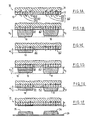
- FIG. 1A shows, in enlarged section, a magnetic recording element 10, of known type, which can be used for implementing the method of the invention.
- this magnetic recording element is of a type analogous to that which has been described and represented in French patent No. 2,402,921 and that it comprises a support 11 formed of a material having a high magnetic permeability, such as iron or mild steel, this support being coated with a layer 12 of a magnetic material with high coercivity such as, for example, the nickel-cobalt magnetic alloy.
- this recording element 10 is magnetized transversely by means of one or more recording heads of known type.
- each of these heads comprises a thin metal core 14 of high magnetic permeability, on which is wound a winding, such as E11 for example connected to an electrical excitation circuit which will be described a little later.
- This core 14 has substantially the shape of an inverted U and has, at its ends, a recording pole, such as P11 for example, and a flow closure pole such as Q11. These two poles are arranged, as shown in FIG.
- the magnetic field is perpendicular to the surface 15 of this layer, so that, in this portion, the magnetization of the layer magnetic 12 is performed well perpendicular to this surface.
- the magnetic field created by this head causes the appearance of a magnetized zone of very small dimensions which, in the remainder of the text, will be designated by the name of elementary magnetic domain, this magnetized zone subsisting even when the winding then ceases to be traversed by a current.
- the dimensions of the recording pole of each head are much smaller than those of the pole for closing the flux of this head, the density of the magnetic flux under the closing pole of the flux is much smaller than that of the magnetic flux under the recording pole. Therefore, the magnetic flux under the closing pole of the flux can neither form elementary magnetized domains in the magnetic layer 12, nor modify the elementary magnetized domains already formed in this layer. As indicated above, the elementary magnetized domains which are thus formed in the magnetic layer 12 have very small dimensions. Thus, in the example described, each of these areas appears, on the surface 15 of the magnetic layer 12 in the form of a very small rectangle whose length is close to 200 ⁇ m and whose width is practically equal to 70 ⁇ m.
- the recording heads and the electrical control circuits of these heads are established, in a manner which will be indicated later, so that these elementary magnetized domains are not isolated from each other on the surface. , but, on the contrary, joined together to form separate groups of elementary magnetized domains, each of these groups comprising the same number k of elementary magnetized domains juxtaposed one with the other.
- the arrangement and the number k of the elementary magnetized domains which constitute each of these groups are established so that each group retains dimensions sufficiently small to allow it to be assimilated to a practically punctual magnetized zone, the dimensions of each zone. indeed remaining less than 500 ⁇ m. For this reason, each group will be designated, in what follows, under the name of magnetized point.
- each magnetized point designated by A in this figure, consists of three elementary magnetized domains D1, D2 and D3, contiguous with one another, the domain D2 being here framed by the domains D1 and D3, each of these domains having the shape of a small rectangle whose length L is substantially equal to three times the width d.
- this width is practically equal to 70 ⁇ m
- the length L of each domain is sen sibly equal to 210 ⁇ .
- each magnetized point A has practically the shape of a square whose length L on the side is substantially equal to 210 ⁇ m.
- each magnetized point could very well be constituted, for example, of four elementary magnetized domains each having the shape of a square of 100 ⁇ m on a side, these four domains being joined to one another to constitute a magnetized point having the shape of a square of 200 ⁇ m on a side.
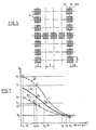
- FIG. 5 shows a set of magnetized points A arranged in a rectangular matrix comprising seven rows and five columns and distributed inside this matrix so as to constitute the image of the character "H ".
- each of these magnetized points here has the shape of a square whose length L on the side is substantially equal to 210 ⁇ m, this square being formed by the juxtaposition of three elementary magnetized domains D1 , D2 and D3 each having the shape of a rectangle whose length L is substantially equal to 210 ⁇ m.
- the spacing pitch P of the rows and columns of the matrix according to which these magnetized points are placed is at least equal to the sum L + d, that is to say at 280 ⁇ m in l 'example considered. Under these conditions, the magnetizations presented by two neighboring magnetized points have no influence on each other.
- the recording element 10 is magnetized so as to form on its surface magnetized points which, being of the type of those which have just been described, all have the same number k of domains elementary magnetized.
- each magnetized point comprises three elementary magnetized domains arranged in a similar manner to that indicated in FIG. 5.
- FIG. 1A only two of these magnetized points, referenced A1 and A2, have been represented for for reasons of simplification but it is understood that the number of these magnetized points can be absolutely arbitrary.
- FIG. 1A only two of these magnetized points, referenced A1 and A2 have been represented for for reasons of simplification but it is understood that the number of these magnetized points can be absolutely arbitrary.
- FIG. 1A also shows the north (N) and south (S) magnetic polarities, as well as the respective magnetizations, of elementary magnetized domains D1, D2 and D3 which constitute these magnetized points A1 and A2, each of these magnetizations being represented by an arrow whose length is proportional to the value of this magnetization.
- N north
- S south
- FIG. 1A that the magnetizations of the different elementary domains all have the same value, but that some are oriented in opposite directions to the others, so that the magnetized points which are formed on the magnetic layer 12 can be classified into two different types. More precisely, the magnetized points which, such as A2, belong to the first type are characterized by the fact that the magnetized domains D1, D2 and D3 which constitute them all have magnetizations oriented in the same direction.
- the magnetized points which, such as A1, belong to the second type are characterized by the fact that the magnetized domains D1, D2 and D3 which constitute them have magnetizations whose directions are reversed when one passes from one of these magnetized domains to another domain which is contiguous to it.
- the direction of these magnetizations is chosen so that the magnetized domains constituting the magnetized points belonging to the first type have a south magnetic polarity (S) on the surface 15 of the element recording 10, while the magnetized domains D1, D2 and D3 which each constitute magnetized points belonging to the second type have respectively, on this surface 15, magnetic polarities south (S), north (N) and south (S) .
- the magnetized dots which, such as A2, belong to the first type are intended to allow the formation, on the printing medium, of images or parts of images which must appear in one of two chosen colors, while the magnetized dots which, such as A1, belong to the second type are intended to allow the formation, on this printing medium, of images or parts of images which must appear in the other color.
- the soft magnetic particles which enter into the composition of this first developer are, in the example described, particles of iron, but they could be formed in any other very magnetic, highly permeable manner, with low remanence, such as, for example , a permalloy or also a soft ferrite corresponding to the formula MO, Fe 2 0 3 , in which is a metal chosen from the group of metals comprising manganese, zinc or nickel.
- This first developer which is deposited on all of this surface 15, is however only attracted by the magnetized points thereof, so that, if we manage to eliminate this developer from this surface, with the exception of magnetized dots, for example by turning the recording element 10 so that the developer particles not subject to the magnetic attraction exerted by the magnetized dots fall under the action of their weight, developer deposits are obtained only on these magnetized points. Under these conditions, each magnetized point is coated, as shown in FIG. 1B, with a layer 18 of first developer, the thickness of this layer being greater than the magnetic attraction force exerted by the magnetized point on which this layer is deposited is higher.
- the force with which each of the developer particles which have been deposited on the same magnetized point is attracted depends not only on the type of this point, that is to say on the direction in which they are oriented. , relative to each other, the magnetizations presented by the elementary magnetized domains which constitute this point, but also by the distance h which separates each particle from this point, as well as physical characteristics of this developer, such as the particle size state and the percentage of magnetic particles of this developer.
- the curve in solid lines 80 represents the variations, as a function of h, of the magnetic attraction force exerted by the magnetized point of the first type A2.
- FIG. 7 also shows the value F G of the force of gravity to which each particle of developer is subjected when this particle is deposited on the recording element 10, this force of gravity being exerted on the against the force of magnetic attraction.
- FIG. 7 shows that, in the example described, a o is substantially equal to 90 ⁇ m, while b o is substantially equal to 83 ⁇ m, these values determining the respective thicknesses of the layers 18 of first developer which are deposited on the points magnetized A1 and A2.
- a second powdery developer is then deposited on the surface 15 of the recording element 10, consisting of hard magnetic particles coated in a thermoplastic resin containing a pigment, the shade is the other of the two aforementioned colors. In the example described, it will be considered that this pigment is black in color.
- the hard magnetic particles which enter into the composition of this second developer are, in the example described, particles of magnetic iron oxide Fe 3 0 4 , but they could be formed of any other magnetic material of high coercivity and high persistence, such as, for example, an iron and nickel alloy containing about 78% nickel, iron carbide, or a hard ferrite corresponding to the general formula MFe0 3 , in which M is a metal chosen from the group of metals including barium, strontium, cobalt and Rare Earths.
- this second developer is carried out under the same conditions as those which have been described for the deposition of the first developer, with the difference however that, the magnetized dots of the second type now being coated with a layer of first developer, the lines of magnetic force which are generated by the elementary magnetized domain D2 of each of these points are largely captured by the particles of the first developer in order to loop back through the elementary magnetized domains D1 and D3 contiguous to this domain D2. This then results in a weakening of the magnetic force exerted by the magnetized points of the second type, the variations of this magnetic force, as a function of the above-mentioned distance h, being represented, in FIG. 7, by the dashed line curve 82.
- this curve 82 is located below the curve 80. Under these conditions, the abscissa a 2 of the point of intersection of the curve 82 with the straight line of ordinate F G is less than that b o of the point d intersection of curve 80 with this same straight line.
- FIG. 7 shows that, in the example described, a 2 is substantially equal to 75 ⁇ m.
- each magnetized point of the second type (such as A1) is coated with a layer 18 of first developer itself covered by a layer 19 of second developer, the thickness of all of these two layers 18 and 19 being equal to a 2 .
- this recording element is subjected to a second retouching operation similar to that which has been described previously.
- this retouching operation which is preferably carried out pneumatically, each of the particles of the two developers which are on the surface 15 of this element is subjected to a constant force, of value F 2 , which is exerted at against the magnetic force F m .
- F 2 of this retouching force has been shown, this value F 2 being preferably chosen so as to remain practically between the values y 1 and y 2 of the respective ordinates of the points J 4 and H 4 where the abscissa line has 1 intersects curves 80 and 82.
- the particles of second developer which, in each of these layers 19, are located at a distance from the surface 15 less than this value a 3 are subjected to a magnetic force whose value is greater than that of the force F 2 , so that these particles are not removed by this retouching force.
- the value of the retouching force F 2 is such that the abscissa a 3 of the point J 2 is less than this value a ,.
- the layers 19 of the second developer which were superimposed on the layers 18 of the first developer are completely eliminated, as shown in FIG. 1 E.
- the intensity of the force of retouching F 2 is less than that of the retouching force F i , none of the particles of the first developer which are still on the magnetized points of the second type (such as A1) are eliminated by the retouching force F 2 , of so that, after this second retouching operation, each magnetized point of the second type remains coated with a layer 18 of first developer, of thickness a ,.
- the retouching force F 2 to have a value such that the line of ordinate F 2 passes substantially through the point of intersection H 4 of the curve 80 with the line of abscissa at 1 , we will obtain even, on the magnetized point of the first type A2, a layer 19 of second developer whose thickness b 3 will be practically equal to that a, of the layer 18 of first developer which covers the magnetized point of the second type A1.
- This second retouching operation can also be carried out with a retouching force whose value F 2 is between y 2 and F 1 ' but in this case there is obtained, on each magnetized point of the first type, a layer of second developer, the l 'thickness b 3 is less than a 1' the thickness of this layer being all the smaller as the value F 2 of the retouching force approaches the value F i .
- this value F T is chosen so as to allow all or almost all of the particles which are on the element 10 to be transferred to the paper strip 20. It is of course possible to use a transfer force whose value F T is such that the ordinate line F T is above curve 81 and does not intersect this curve. Under these conditions, all of the developer particles are transferred onto the paper strip 20. However, it is also possible to choose the value F T of the transfer force in such a way that the line of ordinate F T intersects the curve 81 in one point G whose abscissa e is close to zero, for example is equal to 3 ⁇ m.
- each of the heaps 34 forms on the paper a punctual spot having the shade of the second developer, that is to say black in the example described, while each of the heaps 35 forms on the paper a spot spot having the color of the first developer, that is to say red in the example described.
- FIG. 2 shows a magnetographic printing machine which makes it possible to carry out printing in two colors according to the printing process which has just been described.
- the machine which is shown in this figure comprises a magnetic recording element in the form of a magnetic drum 10 similar to that which has been described and shown in the aforementioned French patent No. 2,402,921, this drum being driven in rotation, in the direction indicated by the arrow R, by an electric motor 25.
- the magnetization of the magnetic layer of this drum is ensured by a magnetic recording member 13 whose structure has been shown in detail in FIGS. 3 and 4.
- the recording device 13 comprises a plurality of magnetic recording heads T11, T12, T13, T21, «, Tn1, Tn2, Tn3 , mounted molded inside an overmolding 16 made of a non-magnetic material such as, for example, a thermosetting resin.
- These heads which are identical, are further separated from each other by a part of this overmolding, which ensures the rigid retention of the heads between them.
- the magnetic heads of the recording member are, according to a more particularly advantageous embodiment of the invention, arranged so as to constitute groups of magnetic heads each comprising k heads.
- each magnetized point comprises three elementary magnetized domains juxtaposed one to the other and aligned in a direction parallel to the generatrices of the drum
- the heads of the recording member 13 are arranged so to form groups of heads each comprising three heads.
- group G1 the heads of the recording member 13 are arranged so to form groups of heads each comprising three heads.
- group G1 the heads of the recording member 13 are arranged so to form groups of heads each comprising three heads.
- the three heads T11, T12 and T13 which constitute the group G1 cause, when they are excited in a manner which will be explained below, the formation, on the magnetic layer 12, of three elementary magnetized domains D1 , D2 and D3 being part of the same magnetized point.
- the three heads T21, T22 and T23 which constitute the group G2 are used to form the three elementary magnetized domains of another magnetized point, etc. ...
- these three domains elementary magnetized are aligned in a direction parallel to the generatrices of the drum 10
- the three heads used for the formation of these three areas could be arranged so that their respective recording poles are also aligned in a direction parallel to these generatrices.
- the three heads of each group are arranged, as can be seen in FIG. 3, not side by side, but on both sides. another of a plane XX 'passing through the axis of rotation 22 of the drum.
- the heads T11 and T13 of the group G1 are placed to the left of this plane XX ', while the head T12 of this group is placed to the right of the plane XX'. It can thus be seen, in the example illustrated in FIG.
- the two framing heads, such as T11 and T13 are spaced from each other by a distance equal to the thickness d of each head, while the third head, such as T12, is arranged directly above the gap between these framing heads.
- the heads T11 and T13 are simultaneously excited for example, by means of an electric current pulse, it will form on the surface 15 of the magnetic layer 12, two elementary magnetized domains D1 and D3 each having a width substantially equal to d, these two domains being spaced from each other by a distance practically equal to d.
- V denotes the linear speed of displacement of the magnetic layer 12 and H the spacing between the two lines L and M above, the time T taken by these two domains to go from their initial position under the poles P11 and P13 at a position below the P12 pole will be equal to H / V.
- the head T12 is excited, it then forms, in the interval separating the two domains D1 and D3 already formed, a third elementary magnetized domain D2, all of these three domains thus constituting a magnetized point.
- the magnetic heads of the recording device fall into two different categories of heads.
- the heads which, such as T11, T13, T21, T23, ..., Tn1, Tn3 are intended to form elementary magnetized domains (such as D1 and D3), always having the same magnetic polarity ( here south) at the surface 15 of the magnetic layer 12, belong to the second category.
- the heads which, such as T12, T22, ...., Tn2 are intended to form the elementary magnetized domains (such as D2) having either a south magnetic polarity or a north magnetic polarity, depending on whether the magnetized points to which these domains belong are of the first or second type, belong to the first category.
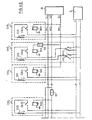
- the electrical pulses which serve to excite the heads of the magnetic recording member 13 come from a pulse source 26 which has been shown diagrammatically in FIG. 2, these pulses being applied to the windings of these heads via a current control and reversing device 27, the structure of which has been shown in detail in FIGS. 6A and 6B assembled.
- FIGS. 6A and 6B assembled for the sake of simplification, only the windings E11, E12, E13, E21, E22, E23 of the heads T11, T12, T13, T21, T22 and T23 are represented.
- each of the n windings E12, E22, Vietnamese, En2 of the heads of the first category that is to say heads T12, T22 ,.
- each of the windings E11, E13, E21, E23, ..., En1 and En3 of the second category heads is part of one of the 2n portions of circui C11, C13, C21, C23, ...., Cn1 and Cn3 each associated respectively with these 2n second category heads.
- the n circuit portions C12, C22, ...., Cn2 further comprise one of n first switches or change-over contacts J12, J22, Vietnamese, Jn2, one of n second switches or change-over contacts K12, K22, ...., Kn2 and one of n relay contacts CB12, CB22, ...., CBn2, the contacts J12, K12 and CB12 being part of the circuit portion C12, the contacts J22, K22 and CB22 forming part of the circuit portion C22, etc.
- each of the circuit portions C12, C22, ...., Cn2 the winding of the head is connected, at one of its ends, to the movable contact blade of the first associated change-over contact and, at the other end to the movable contact blade of the second associated change-over contact, via the associated relay contact.
- Each of the relay contacts CB12, CB22, Vietnamese, CBn2 is controlled by a respective one of n relay coils B12, B22, .
- FIGS. 6A and 6B also show that each of the reversing contacts J12, J22, Vietnamese, Jn2 has two contact terminals designated by the numbers 1 and 2.
- the terminal of contact 2 of each of the first change-over contacts J12, J22, ..., Jn2 is connected to the positive terminal (+) of a current generator G, while contact terminal 2 of each of the second change-over contacts K12 , K22, Vietnamese, Kn2 is connected to the negative (-) terminal of this generator G.
- the contact terminal 1 of each of the change-over contacts J12, J22, ...., Jn2 is connected to the negative terminal (-) of the generator G, while the contact terminal 1 of each of the reversing contacts K12, K22, ...., Kn2 is connected to the positive terminal (+) of the generator G.
- FIGS. 6A and 6B show that the movable contact blades of the two change-over contacts which, such as J12 and K12 for example, are part of the same circuit portion are mechanically coupled so that they can be placed simultaneously t both, either on their contact terminals 1, or on their contact terminals 2. Furthermore, as can be seen in FIGS.
- the head winding is mounted in series with one of 2n relay contacts CB11, CB13, CB21, CB23, whereas, CBn1 and CBn3 each associated respectively at each of these 2n portions of the circuit, each assembly formed by a winding in series with a relay contact being connected to the terminals (+) and (-) of the generator G.
- Each of the relay contacts CB11, CB13, CB21, CB23, ...., CBn1 and CBn3 is controlled by a respective one of 2n relay coils B11, B13, B21, B23, ...., Bn1 and Bn3.
- the coils B11, B12 and B13 which are associated with the magnetic heads T11, T12 and T13 forming part of the group G1 are connected to the output S1 of the source 26, via a conductor W1.
- the coils B21, B22 and B23 which are associated with the magnetic heads T21, T22 and T23 which are part of the group G2 are connected to the output S2 of the source 26, via a conductor W2, and thus after.
- the changeover contacts J12, J22, ??, Jn2 and K12, K22, ...., Kn2 which are part of the circuit portions C12, C22, ising, Cn2 associated with the first category heads are intended to determine the direction in which the magnetization of the elementary magnetized domain D2 of each magnetized point formed on the drum 10 will be oriented, this direction conditioning the type of this point and therefore the color of the spot which this point will allow to form later on paper.
- the two change-over contacts of the same circuit portion are placed on their contact terminals 1
- the current which flows in the winding of the head associated with this circuit portion during all the time when the relay contact which is in series with this winding is closed, circulates in this winding in the direction which, in FIGS.
- the elementary magnetic domain D2 which is formed in the magnetic layer 12 by the head provided with this winding has, on the surface of this layer, a north magnetic polarity (N).
- N north magnetic polarity
- the current which flows in each of the windings of these heads always flows in the same direction (this direction being indicated by the arrows in solid lines), this direction being such that the elementary magnetized domains D1 and D3 which are formed in the magnetic layer 12 by the heads of the second category present and all, on the surface of this layer, a south magnetic polarity (S).
- the magnetized domains D1, D2 and D3 which are formed by the heads T21, T22 and T23, in response to the pulses delivered by the source 26, have respectively a south magnetic polarity (S), a north magnetic polarity (N) and a south magnetic polarity (S) so that the magnetized point formed by these three areas is of the second type.
- the coil B12 is only excited when the time T, counted from the moment when the coils 811 and B13 are excited, has elapsed.
- the coils B21 and B23 are only energized when the time T, counted from the moment when the coil B22 is energized, has elapsed, and so on.
- each of the pulses delivered by the source 26 makes it possible to obtain three magnetized domains D1, D2 and D3 which, being part of the same magnetized point, are contiguous to each other and aligned along the same generator of the drum. 10. If, before the source 26 does not send pulses, the two reversing contacts associated with the head used to form the domain D2 of this point have been previously placed on their contact terminals 1, the magnetized point which is thus obtained is of the first type. On the contrary, if these two reversing contacts have been previously placed on their contact terminals 2, this magnetized point is then of the second type.
- the positioning of the changeover contacts J12, J22, ??, Jn2 and K12, K22, ..., Kn2, on one or the other of their two contact terminals 1 and 2, can be carried out , either manually by the operator before any printing operation, or fully automatically, these reversing contacts being, in the latter case, controlled by actuation means, of known type, excited by the same control unit as that which controls the operation of the pulse source 26. It should also be noted that, depending on the case and application, some of these change-over contacts can be placed on their contact terminals 2, while others are placed on their contact terminals 1, which allows, when printing a character line for example, to obtain characters printed in one of two colors, while the other characters of this line are printed in l other color.
- the current reversing and control device 27 which has been shown in FIG. 2 is constituted, in the example described, by the assembly comprising the reversing contacts J12, J22, ..., Jn2 , and K12, K22, ...., Kn2, the coils B11, B12, B13, B21, B22, B23, ...., Bn1, Bn2, Bn3 and their contacts CB11, CB12, CB13, CB21, CB22, CB23, whereas, CBn1, CBn2, and CBn3, the delay elements R1, R2, ...., Rn, all these members being connected together as illustrated in FIGS. 6A and 6B.
- the control and reversing device 27 then comprises pn circuit portions which, each associated respectively with one of the pn heads of the first category, have a structure similar to that of the portions C12, C22, ...., Cn2, and (kp) n portions of the circuit which, each associated respectively with one of the (kp) n heads of second category have a structure similar to that of the portions C11, C13, C21, C23, ising, Cn1 and Cn3.
- the printing machine produced according to the invention also comprises a first applicator device 40, of known type, which makes it possible to apply to the surface of the drum 10, particles of a first powdery developer contained in a reservoir 49.
- this first powdery developer consists of soft magnetic particles coated in a thermoplastic resin containing a pigment which, in the example described, is colored red.
- the first applicator device 40 is disposed below the drum 10 and it is established so that the layer of first developer which is thus deposited on each of the magnetized points of the first type of this drum has a thickness substantially equal to 83 Jlm, while that which is deposited on each of the magnetized points of the second type of this drum has a thickness substantially equal to 90 ⁇ m.
- this applicator device 40 is of the type which have been described and represented in French patents No. 2,408,462 and 2,425,941 as well as in the French patent application which has been published under No. 2,521,069, this device comprising, on the one hand a rotating magnetic element which brings the developer particles from the reservoir 49 to the vicinity of the surface of the drum 10, on the other hand a deflector interposed between this magnetic element and the drum to constitute a bucket in which the particles collected by the deflector accumulate, this deflector leaving between it and the drum a very small opening, of the order of 1 millimeter, through which pass the particles which have come to rest against the surface of the drum.
- the magnetized points of the drum 10 which have thus been coated with a layer of first developer then pass in front of a retouching device 41 which makes it possible, on the one hand, to remove the particles of developer remaining on the drum 10 outside the magnetized points , on the other hand to remove the first developer found on the magnetized points of the first type.
- the retouching device 41 which is used for this operation can be of the electrostatic or pneumatic type. It will be considered that, in the example described, this retouching device 41 is of the type which has been described and represented in French patent No. 2,411,435 and that it is adjusted so as to completely remove the first layers.
- this second powder developer consists of hard magnetic particles coated in a thermoplastic resin containing a pigment, this pigment here being black.
- the second applicator device 42 is practically disposed below the drum 10 and it is established so that the layer of second developer which is thus deposited on each of the magnetized points of the first type of this drum has a thickness substantially equal to 83 ⁇ m , while the second developer layer which is deposited superimposed on each of the first developer layers covering the magnetized dots of the second type has a thickness substantially equal to 48 ⁇ m. Since, in the example described, the thickness of the layer of first developer covering the points of the second type is close to 27 ⁇ m, the total thickness of the two layers of developer on each of the magnetized points of the second type is therefore practically equal to 75 ⁇ m.
- the magnetized points of the drum which have passed past the second applicator device 42 then pass in front of a second retouching device 43 similar to the retouching device 41.
- This retouching device 43 is adjusted, in the example described, so as to completely eliminate the layers of second developer which are superimposed on the layers of first developer covering the magnetized points of the second type, and in reducing the thickness of the layers of second developer which cover the magnetized points of the first type without this thickness becoming less than that of 1 layers of the first developer on the magnetized points of the second type.
- each of the magnetized dots of the second type is coated with a layer of first developer, the thickness of which is substantially equal to 27 pm, while each point magnetized the first type is coated with a layer of second developer of which the thickness is close to 30 li m.
- the magnetized points of the drum 10 which have undergone this second retouching operation are then brought into contact with a strip of paper 20 which is applied to the drum 10, as shown in FIG. 2, under the action exerted by a pressure roller 45
- the force with which the strip 20 is applied to the drum 10 by the pressure roller 45 can be adjusted, by known means (not shown), so as to cause a practically total transfer of all the layers of developer which remain on the drum 10 after passing in front of the retouching device 43.
- the value F T of this force is, as shown in FIG. 7, greater than that of F 1 which was mentioned above so that, ultimately, the layers of first and of second developers which were deposited on the magnetized points of the drum 10 are transferred almost entirely on the paper strip 20.
- the machine which has been shown in FIG. 2 also includes a developer fixing device 46 under which the paper strip 20 passes when the transfer operation which has just been described has been carried out.
- the fixing device 46 which consists, in the example described, of an electric heating element with infrared rays, is intended to permanently fix the developers which have been transferred to the strip of paper 20. It is necessary to point out here that this fixing device 46 is adjusted so as to cause a frank fusion of the two developers, without thereby producing an inflammation or even a deterioration of the paper strip 20, the melting point of these developers being, in the 'example described, lower than 140 ° C. Under these conditions, each pile as 34 forms, after being melted and then cooled on paper, a spot spot having the shade of the second developer, while each pile as 35 forms, after having been melted then cooled on paper, a spot spot having the color of the first developer.
- the machine shown in Figure 2 further comprises a cleaning device which, consisting of a brush 47 in the example described, ensures the cleaning of the parts of the surface of the drum 10 which have passed in front of the transfer station. After this cleaning, these parts pass in front of an erasing device 48, of the electromagnetic type, which erases the latent magnetic images carried by these parts, so that these parts are again capable of being magnetized when they pass again. then in front of the magnetic recording device 13.
- a cleaning device which, consisting of a brush 47 in the example described, ensures the cleaning of the parts of the surface of the drum 10 which have passed in front of the transfer station. After this cleaning, these parts pass in front of an erasing device 48, of the electromagnetic type, which erases the latent magnetic images carried by these parts, so that these parts are again capable of being magnetized when they pass again. then in front of the magnetic recording device 13.
Landscapes
- Nanotechnology (AREA)
- Chemical & Material Sciences (AREA)
- Engineering & Computer Science (AREA)
- General Physics & Mathematics (AREA)
- Health & Medical Sciences (AREA)
- Life Sciences & Earth Sciences (AREA)
- General Health & Medical Sciences (AREA)
- Molecular Biology (AREA)
- Crystallography & Structural Chemistry (AREA)
- Physics & Mathematics (AREA)
- Printers Or Recording Devices Using Electromagnetic And Radiation Means (AREA)
- Impression-Transfer Materials And Handling Thereof (AREA)
- Developing Agents For Electrophotography (AREA)
Applications Claiming Priority (2)
| Application Number | Priority Date | Filing Date | Title |
|---|---|---|---|
| FR8412191A FR2568697B1 (fr) | 1984-08-01 | 1984-08-01 | Procede et machine d'impression magnetographique |
| FR8412191 | 1984-08-01 |
Publications (2)
| Publication Number | Publication Date |
|---|---|
| EP0172767A1 EP0172767A1 (fr) | 1986-02-26 |
| EP0172767B1 true EP0172767B1 (fr) | 1987-11-25 |
Family
ID=9306710
Family Applications (1)
| Application Number | Title | Priority Date | Filing Date |
|---|---|---|---|
| EP85401503A Expired EP0172767B1 (fr) | 1984-08-01 | 1985-07-22 | Procédé et machine d'impression magnétographique |
Country Status (5)
| Country | Link |
|---|---|
| US (1) | US4646108A (enExample) |
| EP (1) | EP0172767B1 (enExample) |
| JP (1) | JPS6157975A (enExample) |
| DE (1) | DE3561086D1 (enExample) |
| FR (1) | FR2568697B1 (enExample) |
Families Citing this family (3)
| Publication number | Priority date | Publication date | Assignee | Title |
|---|---|---|---|---|
| US5196882A (en) * | 1990-11-28 | 1993-03-23 | Seikosha Co., Ltd. | Magnetic recording color microcapsule and a magnetic recording device using the same |
| NL1003680C2 (nl) * | 1996-07-25 | 1998-01-28 | Oce Tech Bv | Beeldafdrukinrichting. |
| KR102334471B1 (ko) * | 2019-04-30 | 2021-12-03 | 울산과학기술원 | 입체감이 구현된 자성재료 인쇄 필름의 제조방법 및 그를 이용하여 제조된 자성재료 인쇄 필름 |
Family Cites Families (9)
| Publication number | Priority date | Publication date | Assignee | Title |
|---|---|---|---|---|
| GB1183041A (en) * | 1965-12-24 | 1970-03-04 | Int Computers Ltd | Priting Apparatus |
| GB1240675A (en) * | 1968-02-15 | 1971-07-28 | Creed & Co Ltd | Improvements in data printing apparatus |
| US3823406A (en) * | 1972-03-10 | 1974-07-09 | Bell & Howell Co | Methods, apparatus and media for magnetically recording information |
| US3824601A (en) * | 1972-03-28 | 1974-07-16 | Bell & Howell Co | Multi-color magnetic image recording and media |
| US3965478A (en) * | 1973-06-22 | 1976-06-22 | Raytheon Company | Multicolor magnetographic printing system |
| FR2518773A1 (fr) * | 1981-12-23 | 1983-06-24 | Cii Honeywell Bull | Procede et machine d'impression magnetographique |
| FR2518771A1 (fr) * | 1981-12-23 | 1983-06-24 | Cii Honeywell Bull | Procede et machine d'impression magnetographique |
| FR2518772A1 (fr) * | 1981-12-23 | 1983-06-24 | Cii Honeywell Bull | Procede et machine d'impression magnetographique |
| FR2518770B1 (fr) * | 1981-12-23 | 1985-09-13 | Cii Honeywell Bull | Procede et machine d'impression magnetographique |
-
1984
- 1984-08-01 FR FR8412191A patent/FR2568697B1/fr not_active Expired
-
1985
- 1985-07-01 JP JP60144429A patent/JPS6157975A/ja active Granted
- 1985-07-22 DE DE8585401503T patent/DE3561086D1/de not_active Expired
- 1985-07-22 EP EP85401503A patent/EP0172767B1/fr not_active Expired
- 1985-07-30 US US06/760,480 patent/US4646108A/en not_active Expired - Lifetime
Also Published As
| Publication number | Publication date |
|---|---|
| JPS6157975A (ja) | 1986-03-25 |
| US4646108A (en) | 1987-02-24 |
| JPH0437428B2 (enExample) | 1992-06-19 |
| FR2568697A1 (fr) | 1986-02-07 |
| FR2568697B1 (fr) | 1987-03-20 |
| EP0172767A1 (fr) | 1986-02-26 |
| DE3561086D1 (en) | 1988-01-07 |
Similar Documents
| Publication | Publication Date | Title |
|---|---|---|
| FR2564609A1 (fr) | Procede et appareil de developpement | |
| BE898184A (fr) | Révélateur électrographique et procédé de développement d'image électrographique l'utilisant. | |
| FR2597993A1 (fr) | Appareil rotatif de developpement et dispositif de transmission d'agent de virage | |
| FR2544093A1 (fr) | Appareil de developpement | |
| EP0172767B1 (fr) | Procédé et machine d'impression magnétographique | |
| CH435981A (fr) | Appareil d'impression électrostatique avec application de poudre | |
| EP0012649A1 (fr) | Tête de lecture magnétique | |
| EP0082740B1 (fr) | Procédé et machine d'impression magnétographique | |
| EP0082739B1 (fr) | Procédé et machine d'impression magnétographique | |
| CA1261912A (fr) | Procede et machine d'impression magnetographique | |
| EP0082741B1 (fr) | Procédé et machine d'impression magnétographique | |
| EP0082742B1 (fr) | Procédé et machine d'impression magnétographique | |
| FR2531797A1 (fr) | Support d'enregistrement magnetique comportant un film mince en un metal ferromagnetique sur un support non magnetique | |
| EP0099763B1 (fr) | Dispositif pour l'application de particules solides de révélateur sur l'élément d'enregistrement d'une imprimante non impact | |
| EP0142446B1 (fr) | Appareil de développement d'images magnétiques latentes | |
| CA2126283A1 (fr) | Procede d'impression d'au moins une image et presse pour la mise en oeuvre | |
| EP0315509B1 (fr) | Procédé pour fixer un révélateur pulvérulent déposé sur une feuille et dispositif pour fixer ce révélateur selon ce procédé | |
| FR2600178A1 (fr) | Element d'enregistrement magnetique destine a etre utilise dans une imprimante magnetographique | |
| EP0193691B1 (fr) | Appareil d'impression sans frappe | |
| FR2626529A1 (fr) | Dispositif pour appliquer, de facon intermittente, des particules d'un revelateur pulverulent sur la surface d'enregistrement d'une imprimante magnetographique | |
| FR2490847A1 (fr) | Element d'enregistrement magnetique | |
| EP0635769B1 (fr) | Média pour imprimantes magnétographiques et utilisation d'un tel média | |
| FR2527798A1 (fr) | Dispositif de transfert d'une encre magnetique | |
| FR2522838A1 (fr) | Dispositif a moyens de redressement de lignes de force, pour la revelation d'images latentes magnetiques portees par un support magnetique a magnetisation transversale | |
| EP0291392B1 (fr) | Substance pulvérulente pour la lubrification du support d'enregistrement d'une imprimante magnétique |
Legal Events
| Date | Code | Title | Description |
|---|---|---|---|
| PUAI | Public reference made under article 153(3) epc to a published international application that has entered the european phase |
Free format text: ORIGINAL CODE: 0009012 |
|
| AK | Designated contracting states |
Designated state(s): BE DE GB IT NL |
|
| 17P | Request for examination filed |
Effective date: 19860129 |
|
| 17Q | First examination report despatched |
Effective date: 19870331 |
|
| GRAA | (expected) grant |
Free format text: ORIGINAL CODE: 0009210 |
|
| RAP1 | Party data changed (applicant data changed or rights of an application transferred) |
Owner name: BULL S.A. |
|
| ITF | It: translation for a ep patent filed | ||
| AK | Designated contracting states |
Kind code of ref document: B1 Designated state(s): BE DE GB IT NL |
|
| REF | Corresponds to: |
Ref document number: 3561086 Country of ref document: DE Date of ref document: 19880107 |
|
| GBT | Gb: translation of ep patent filed (gb section 77(6)(a)/1977) | ||
| PLBE | No opposition filed within time limit |
Free format text: ORIGINAL CODE: 0009261 |
|
| STAA | Information on the status of an ep patent application or granted ep patent |
Free format text: STATUS: NO OPPOSITION FILED WITHIN TIME LIMIT |
|
| 26N | No opposition filed | ||
| ITTA | It: last paid annual fee | ||
| PGFP | Annual fee paid to national office [announced via postgrant information from national office to epo] |
Ref country code: BE Payment date: 19980623 Year of fee payment: 14 |
|
| PGFP | Annual fee paid to national office [announced via postgrant information from national office to epo] |
Ref country code: NL Payment date: 19980731 Year of fee payment: 14 |
|
| PG25 | Lapsed in a contracting state [announced via postgrant information from national office to epo] |
Ref country code: BE Free format text: LAPSE BECAUSE OF NON-PAYMENT OF DUE FEES Effective date: 19990731 |
|
| PGFP | Annual fee paid to national office [announced via postgrant information from national office to epo] |
Ref country code: GB Payment date: 19990812 Year of fee payment: 15 |
|
| PGFP | Annual fee paid to national office [announced via postgrant information from national office to epo] |
Ref country code: DE Payment date: 19990928 Year of fee payment: 15 |
|
| BERE | Be: lapsed |
Owner name: S.A. BULL Effective date: 19990731 |
|
| PG25 | Lapsed in a contracting state [announced via postgrant information from national office to epo] |
Ref country code: NL Free format text: LAPSE BECAUSE OF NON-PAYMENT OF DUE FEES Effective date: 20000201 |
|
| NLV4 | Nl: lapsed or anulled due to non-payment of the annual fee |
Effective date: 20000201 |
|
| REG | Reference to a national code |
Ref country code: GB Ref legal event code: 732E |
|
| PG25 | Lapsed in a contracting state [announced via postgrant information from national office to epo] |
Ref country code: GB Free format text: LAPSE BECAUSE OF NON-PAYMENT OF DUE FEES Effective date: 20000722 |
|
| GBPC | Gb: european patent ceased through non-payment of renewal fee |
Effective date: 20000722 |
|
| PG25 | Lapsed in a contracting state [announced via postgrant information from national office to epo] |
Ref country code: DE Free format text: LAPSE BECAUSE OF NON-PAYMENT OF DUE FEES Effective date: 20010501 |