EP0172467A2 - Dispositif à capteur de proximité répondant à l'approche des couteaux vers la barre de cisaillement d'une moissonneuse de fourrage - Google Patents
Dispositif à capteur de proximité répondant à l'approche des couteaux vers la barre de cisaillement d'une moissonneuse de fourrage Download PDFInfo
- Publication number
- EP0172467A2 EP0172467A2 EP85109661A EP85109661A EP0172467A2 EP 0172467 A2 EP0172467 A2 EP 0172467A2 EP 85109661 A EP85109661 A EP 85109661A EP 85109661 A EP85109661 A EP 85109661A EP 0172467 A2 EP0172467 A2 EP 0172467A2
- Authority
- EP
- European Patent Office
- Prior art keywords
- voltage
- signal
- output
- capacitor
- proximity
- Prior art date
- Legal status (The legal status is an assumption and is not a legal conclusion. Google has not performed a legal analysis and makes no representation as to the accuracy of the status listed.)
- Withdrawn
Links
Images


Classifications
-
- B—PERFORMING OPERATIONS; TRANSPORTING
- B26—HAND CUTTING TOOLS; CUTTING; SEVERING
- B26D—CUTTING; DETAILS COMMON TO MACHINES FOR PERFORATING, PUNCHING, CUTTING-OUT, STAMPING-OUT OR SEVERING
- B26D7/00—Details of apparatus for cutting, cutting-out, stamping-out, punching, perforating, or severing by means other than cutting
- B26D7/08—Means for treating work or cutting member to facilitate cutting
-
- A—HUMAN NECESSITIES
- A01—AGRICULTURE; FORESTRY; ANIMAL HUSBANDRY; HUNTING; TRAPPING; FISHING
- A01F—PROCESSING OF HARVESTED PRODUCE; HAY OR STRAW PRESSES; DEVICES FOR STORING AGRICULTURAL OR HORTICULTURAL PRODUCE
- A01F29/00—Cutting apparatus specially adapted for cutting hay, straw or the like
- A01F29/09—Details
- A01F29/16—Safety devices, e.g. emergency brake arrangements
-
- B—PERFORMING OPERATIONS; TRANSPORTING
- B26—HAND CUTTING TOOLS; CUTTING; SEVERING
- B26D—CUTTING; DETAILS COMMON TO MACHINES FOR PERFORATING, PUNCHING, CUTTING-OUT, STAMPING-OUT OR SEVERING
- B26D7/00—Details of apparatus for cutting, cutting-out, stamping-out, punching, perforating, or severing by means other than cutting
- B26D7/26—Means for mounting or adjusting the cutting member; Means for adjusting the stroke of the cutting member
Definitions
- the invention relates to a device, in particular on forage harvesting machines, with a plurality of proximity sensors, each of which is fixed with respect to the shear bar and is arranged close to one of a plurality of cutting heads, each having a plurality of cutting knives, and generates an approximation signal which indicates the approach of a cutting knife to the Shear bar corresponds with the features of the preamble of claim 1.
- Such a device is known from DE-A-29 43 828.
- proximity sensors are used in recesses in the shear rod, which generate a magnetic field which is changed by the cutting blades of the cutting head moving past.
- the signal generated by the proximity sensor is fed to an evaluation circuit in which the signal is integrated during the cycle time and compared with preset threshold values.
- a detector device detects the greatest value of the integrated signal and generates a signal proportional to the minimum distance between the shear bar and the cutting blades. This is displayed by a measuring instrument.
- the average distance between the knives and the shear bar is determined by the output voltage of the integration device being fed to a low-pass filter, the output signal of which is also displayed on the measuring instrument.
- a further detector is provided which is connected to the output of the integration device via a sample and hold circuit in order to record the greatest distance between the knives and the shear bar.
- the distances of all successive knives are reproduced in the form of a graduated signal via the circuit.
- the particular advantage is, inter alia, that a warning device which is independent of the display device and is controlled by a separate circuit is provided.
- This separate circuit responds to whether one or more of the pulses coming from the comparator devices is generated or not, and at the same time. can also indicate if none of the comparator devices delivers a pulse.
- the warning device responds if the signals from all proximity sensors are missing, e.g. may be the case when starting the machine.
- the arrangement is advantageously further developed according to claim 2. This enables the driver to check only a certain cutting element. If a warning signal occurs, the driver can easily check which of the proximity sensors is faulty.
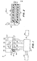
- the forage harvester has a cutting device 10 which has a shear bar 12 and four rotating cutting heads 14a, 14b, 14c and 14d. Each cutting head in turn has a plurality of knives or blades 13. Corresponding to the four cutting heads, four proximity sensors 16a, 16b, 16c and 16d are also provided in the new monitoring device. Each proximity sensor is arranged in a bore that extends through the shear rod 12.
- each proximity sensor 16 comprises a permanent magnet 18, which is arranged at one end of a ferromagnetic or magnetically conductive rod 20.
- a sensor winding 22 coaxially surrounds the rod 20.
- the magnet 18 and the rod 20 are arranged in a hollow cylindrical plastic housing 24 which is fastened to a bore 26 in the shear rod 12.
- the outer end of the mag Neten 18 is preferably flush with the end face of the shear bar 12, namely at the point 13 initially located. Movement of each blade 13 past the proximity sensor 16 results in the generation of an electrical signal Vs which appears as a voltage across the terminals of the winding 22.
- the output terminals of the four proximity sensors are connected in a monitor circuit.
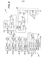
- the monitor circuit 30 can generate output signals containing information regarding the distance between the knife and the shearbar from one or more selected cutter heads 14a, 14b, 14c and 14d. This information is displayed to the driver by a display panel 34.
- the monitor circuit 30 comprises four identical signal evaluation circuits 40a, 40b, 40c and 40d. Each of these evaluation circuits is connected to the winding connections of an associated proximity switch.
- each evaluation circuit 40 has a resistor R1, which is connected to a connection of the sensor winding and to the common connections of the resistors R2 and R3 and via a filter capacitor C1.
- the other connection of the sensor winding 22 is connected to the output and to the (-) input of an isolating amplifier 42 and to the (+) input of a working amplifier 44.
- the (+) input of the amplifier 42 is with a reference voltage Vref of, for example. 1.2 volts DC connected.
- the output of amplifier 42 is grounded via a capacitor C2 and connected to the anode of a diode D1 and to the (-) input of a comparator 46 via resistor R4.
- the cathode of the diode Dl is connected to the other terminal of the resistor R3 and to the (+) input of the comparator 46.
- the (-) input of comparator 46 is in turn grounded through resistor R5.
- the other terminal of resistor R2 is connected to the (-), - input of amplifier 44.
- the (-) input of amplifier 44 is also connected to the source (S) and substrate (SUB) terminals of a field transistor (FET) 45 via resistor R6.
- the (-) input and the output of the amplifier 44 are connected to one another by a resistor R7 and an integration capacitor C3 lying in parallel therewith.
- the output of amplifier 44 is also connected to the drain port (D) of field transistor 45 and to the (+) input of a variable gain amplifier 48.
- the gate (G) of field transistor 45 is grounded via a capacitor C4 and connected via a resistor R8 to a terminal 47, which in turn is connected to the output of a comparator 46.
- the gate (G) of field transistor 45 is also connected to the anode of a diode D2 via resistor R9. The cathode of this diode D2 is connected to the connection 47.
- a resistor R10 is between the reference voltage at the outlet of the isolation amplifier 42 and the (-) input of the amplifier 48. This comprises a variable resistor R11 between the terminal 49 and its (-) input. By changing the resistance R11, the amplification factor of the amplifier 48 can be changed in order to adapt to variations in the signal strength at the proximity sensors 16a, 16b, 16c and 16d due to changes in the proximity sensors themselves or due to changes in their mounting position.
- the output of amplifier 48 is connected to terminal 49 and to the input terminal of a CMOS switch.
- the output terminal of this switch 50 is connected to the (+) input of an isolation amplifier 52 with a constant gain factor via resistor R13.
- the (+) input of the isolating amplifier 52 is grounded via a capacitor C6, which is used to form an average value.
- the (-) input of the isolation amplifier 52 is connected to its output. The high impedance of the isolating amplifier 52 prevents the capacitor C6 from being discharged through the output line 53 of the evaluation circuit 40.
- connection 47 is connected to the A input of a monostable multivibrator 56.
- the multivibrator 56 generates a relatively short positive or ready pulse at the Q output, the pulse lasting a little less than 1 millisecond.
- the multivibrator is triggered by the transition from a low to a high value at the output of the comparator 46.
- the Q output of the multivibrator 56 is connected to the connection 55 and to the input of the AND gate 58 of a logic circuit 57.
- the other input of gate 58 is connected to the output of an OR gate 60.
- Control switching lines 62 and 64 are connected to the inputs of gate 60.
- the output of the AND gate 58 is connected to the control input C of the COMS switch. The switch is open as long as the output of gate 58 is low and is closed when the output on gate 58 is high.
- FIG. 3 shows that the output lines 53a-53d of the evaluation circuits 40a-40d are each connected to the anode of an associated diode D3a-D3d.
- the cathodes of the diodes D3a-D3d are connected together and connected to the (+) input of an isolation amplifier 70 with a constant gain factor via the line 68.
- the (+) input of amplifier 70 is grounded through resistor R15.
- a variable offset voltage Vos is tapped by a potentiometer R16, which lies between a voltage source + Vcc (for example of +8 volts DC) and ground. This offset voltage is applied to the (+) input of an isolating amplifier 72 with a fixed gain factor. The output of the isolation amplifiers 70 and 72 is connected to their respective (-) input.
- the voltages Vmax and Vos are fed to the (+) and (-) inputs of a differential amplifier 74 with a constant gain factor.
- the output voltage Vd of the differential amplifier 74 is applied to the (+) input of a variable gain amplifier 76, the gain of which can be set, for example, between 1 and 6 by changing the variable resistor R17 which is between the (-) input and the output of the gain factor 76.
- the (-) input of amplifier 76 is grounded through resistor R18.
- the output voltage Vo of the amplifier 76 is connected to a measuring driver circuit 80.
- This comprises a working amplifier 82, the (+) input of which is connected to the output of the amplifier 76.
- the output of amplifier 82 is connected to the base of a 2N222 transistor Q2.
- the collector of this transistor is connected to the voltage source + Vcc.
- the emitter of the Transistor is connected to the (-) input of operational amplifier 82 and to the anode of diode D4.
- the cathode of this diode D4 is connected to earth via resistor R19.
- a conventional, analog voltmeter 84 is connected in parallel with the resistor R19. It would also be possible to provide a digital display device (not shown) instead of the voltmeter 84 if the output signal Vo is converted by corresponding analog / digital converters.
- the switch module 32 is preferably mounted in the driver's cab and comprises four switches 5a-5d. One side of each switch is connected to the voltage source + Vcc. The other side of each switch 5a-5d is connected to the respective input of a NOR gate 92 of a logic circuit 94. The inputs of gate 92 are connected to ground via identical resistors R20a-R20d. The inputs of the gate 92 are also connected to control lines 62a-62d from logic circuits 57 of the evaluation circuits 40a-40d. The output of gate 92 is connected to control lines 64a-64d of logic circuit 57.
- each of the four evaluation circles 40a-40d can be connected to a corresponding circle of four identical circles 200a-200d, one of which is shown, for example, in FIG. 6.
- Each of these circles 200a-200d includes a worn or misaligned blade detector unit 202, a missing or broken blade detector unit 204 and a unit 206 which determines whether corresponding proximity sensors 16a-16d have become ineffective.
- Each of the circuits 200a-200d comprises a monostable multivibrator 208 with a grounded A input and a B input, which is connected to the connection 47 of the evaluation circuit 40 for receiving the voltage Vb.
- the multivibrator 208 generates a positive pulse at its Q output, the duration of which is equal to the duration of the working period of the multivibrator 56 of the evaluation circuit 40, depending on the transition from high values to low values of the voltage Vb.
- Each unit 202 includes a CMOS switch 210 with an input terminal connected to the terminal 49 of the evaluation circuit 40 to receive the amplified integrated capacitor voltage Vc.
- the control input C of the switch 210 is connected to the connection 55 of the evaluation circuit 40.
- the output terminal of switch 210 is connected to ground through a selection capacitor C7.
- the output of switch 210 is also connected to the input of a single gain amplifier 212 and to the anode of the first (D5) of two diodes D5 and D6 connected in series.
- the cathode of diode D6 is grounded through resistor R21 and connected to the (+) input of comparator 214.
- the output of the isolation amplifier 212 is connected to the input terminal of the CMOS switch 216, whose control C inlet is connected to the Q outlet of the monostable multivibrator 208.
- the output terminal of switch 260 is grounded through a selection capacitor C8 and connected to the (-) inlet of comparator 214.
- the isolation amplifier 212 provides isolation between the select capacitors C7 and C8 to prevent the voltage of the capacitor C8 from affecting the voltage on the capacitor C7.
- Each unit 204 comprises an inverter 220, one inlet of which is connected to the connection 47 of the evaluation circuit 40 for receiving the voltage Vb.
- the outlet of the Inverter 220 is connected to the base of a transistor Q3 via resistor R22.
- the base of this transistor is grounded through capacitor C9.
- the emitter of transistor Q3 is grounded, while the collector is connected to the voltage source + Vcc through resistor R23, to the (+) input of fixed gain isolation amplifier 222, and to ground through capacitor C10.
- the collector of transistor Q3 is connected to the anode of two diodes D7 and D8 in series.
- the cathode of diode D8 is grounded via resistor R24 and connected to the (+) input of comparator 224.
- isolation amplifier 222 is connected to its (-) inlet and to the inlet port of another CMOS switch 226.
- Control port C of switch 226 is connected to the Q output of monostable multivibrator 208.
- the output port of switch 226 is through the Selection capacitor C11 is grounded and connected to the (-) inlet of comparator 224.
- the outlet of this comparator is connected to output line 208.
- Each unit 206 includes an inverter 230 which is connected to the terminal 47 for receiving the voltage Vb.
- the output of inverter 230 is connected to one side of a capacitor C12 via resistor R25.
- the other side of the capacitor C12 is connected to the base of a transistor Q4 and to the cathode of the diode D9.
- the anode of this diode and the emitter of the transistor are grounded.
- the collector of transistor Q4 is connected to voltage source Vcc through resistor R26, to ground through capacitor C13, and to the inlet of a reverse Schmitt trigger 232.
- the outlet of this trigger 232 is connected to the output line 234 and via an inverter 238 to an output line 236.
- the output lines 218, 228, 234 and 236 of the circuits 200a-200d are connected to corresponding inlets of the circuits 240 and 260 in FIGS. 7 and 8, respectively.
- Circuit 240 of FIG. 7 includes a multiple input NOR gate 242. Four of these inputs are connected to corresponding output lines 218a-218d of units 202a-202d of circuits 200a-200d. Another four of the inputs of the gate are connected to corresponding output lines 228a-228d of the units 204a-204d of the circuits 200a-200d.
- the output of gate 242 is connected to the B input of a monostable multivibrator 244, the A inlet of which is grounded.
- the multivibrator 244 generates a positive pulse of predetermined duration at the Q output depending on the transitions from high values to low values at the B input.
- the Q output is connected to a lamp driver circuit 246. This can be a cascaded double transistor current amplifier, which in turn controls lamps or other indicators 248 on the display panel 34 when the Q output of the multivibrator 244 is high.
- Circuit ' 260 in Figure 8 includes an OR gate 262. Each inlet is connected to units 206 of circuits 200a-200d via a corresponding output line 234a-234d. Circuit 260 includes another OR gate 264, the two inputs of which are connected to corresponding output lines 236a-236d of units 206 of circuits 200a-200d.
- the outlets of gates 262 and 164 are connected to the inlets of an AND gate 266, the outlet of which is connected to the base of a transistor Q5.
- the collector of the transistor is connected to the voltage source + Vcc.
- the emitter of the transistor is connected to the inlet of a lamp driver circuit 272, which is similar to that Driver circuit 246 can be formed.
- driver circuit 272 The connection is made via resistor R27 also with the cathode of a diode D10 and via resistor R28 with earth.
- the inlet of driver circuit 272 is connected to the anode of diode D10 and to capacitor C14.
- a Schmitt trigger can be arranged between R27 and the driver circuit 272. Its hysteresis can prevent the driver circuit 272 from operating unstably if the voltage on the capacitor C40 is close to the limit level of the driver circuit 272.
- the driver circuit drives a lamp or other display device 274 on the display board 34.
- the display panel 34 in FIG. 1, which includes lamps and meters 84 and lamps 248 and 274, can be assembled so that it is visible to the operator when in his cab, not shown , so that the play between the knives and the shear bar can be easily monitored during the operation of the forage harvester. It could also be desirable to mount the indicator 32 so that it is also visible from a position the driver assumes when adjusting or adjusting the play of the shear bar, e.g. after sharpening the knives. This would be e.g. Accessible with a movable display board or with separate display boards that are arranged so that they are also visible from the setting position. In this way, the operator or the driver can use the display device to use the measured values when adjusting the position of the shear bar after the sharpening process.
- the monitoring device works as follows: The movement of a knife 13 of one of the cutting heads 14a-14d in the vicinity of the associated An Proximity sensor 16a-16d interferes with the magnetic field generated by the permanent magnet 18. The change in the magnetic field leads to a sensor voltage Vs across the sensor winding 22, as best shown in FIG. 5. When the blade 13 moves away from the proximity sensor 16, the polarity of this voltage Vs is reversed from the polarity during the approach. The voltage Vs therefore reverses its polarity so that its magnitude is neutral with respect to a reference voltage Vref at the moment when the distance between the blade 13 and the proximity sensor 16 is at a minimum in a direction along the axis of the winding 22.
- the normally high voltage Vb at the output of the comparator 46 and at the terminal 47 is low, as shown at point 100 in Fig. 5, as long as the voltage Vs is less than the reference voltage Vref.
- the low level of voltage Vb turns off field transistor 45 so that amplifier 44 can charge integration capacitor C3 to a value as shown at 102.
- the peak voltage Vs generated by proximity sensor 16 is a function of the air gap to be measured, the speed of the moving knife, and other constant factors, such as the field strength of the magnet, the number of turns of the windings 22, of different impedances and also geometrical arrangements.
- the voltage Vs at a low knife speed has a relatively lower amplitude but a relatively longer duration.
- the voltage Vs at higher knife speeds has a larger amplitude but a shorter duration.
- the area under the time-voltage curve Vs in FIG. 5 is essentially only a function of the smallest distance or gap between the knife 13 and the proximity sensor 16.
- the voltage Vc across the capacitor C3 is thus an integration function the sensor voltage Vs and is therefore characteristic of the smallest distance between the blade and the proximity sensor.
- the output voltage Vb switches from a low value to a high value, as indicated at point 106.
- This transition of the voltage Vb triggers the monostable multivibrator 56.
- This pulse closes the normally open CMOS switch 50 for a corresponding period of time via the AND gate 58.
- the switch 50 is closed, the voltage Vf corresponds to the peak value of the voltage Vc.
- the voltage Vf arrives at the average capacitor C6 via resistor R13.
- the resistor R9 preferably has an impedance which is substantially smaller than that of the resistor R8, so that the capacitor C4 can quickly discharge through the resistor R8 and the diode D4 to the field transistor 45 depending on the Switch off occurrence of the transition from high to low of the voltage Vb, as indicated at 114.
- each evaluation circuit 40a-40d produces an average output voltage Vave (a) - (d) in the manner just described to represent an average minimum gap between the blade and proximity sensor of the corresponding cutting heads 14a-14d .
- a diode network formed by diodes D3a-D3d generates a voltage Vmax on line 68 which is equal to the highest value of the voltages Vave (a) - (d) less the small voltage drop of 0.7 Volts on the diode.
- a constant gain differential amplifier 74 generates a differential voltage Vd which is equal to the difference between the separated voltages Vmax and the offset voltage Vos.
- the differential voltage Vd is amplified by an amplifier 76 with a variable gain factor in order to obtain an output voltage Vo which is fed to the driver circuit 80 for the measuring device 84.
- the measuring device 84 thus generates a recognizable or perceptible signal which corresponds to the average distance between the blade and the proximity sensor of the cutting head or cutting segment 14, which shows the lowest average separation between the blade and the proximity sensor.
- the output of the OR gate 60 of the evaluation circuit 40a remains high, so that the pulse of the monostable multivibrator now periodically closes the switch 50 via the AND gate, so that a voltage Vave ( a) appears at the output 53a of the evaluation circuit 40a, which does not have the value zero.
- the voltage Vmax in the line 68 thus only represents the voltage Vave (a) and the measuring device 84 displays a value which corresponds only to the cutting head 14a.
- any combination of circuits 40a-40d can be disabled by opening or closing a corresponding combination of switches 5a-5d.
- the display device 84 always shows a value which reflects the average separation between the knife and the proximity sensor of the cutting segment, which corresponds to the cutting segment with the smallest distance, specifically with reference to the circles 40a brought into effect -40d.
- Each unit 202 operates as follows: The voltage Vc generated by the movement of the first blade 13 is selected and from the capacitor C7, triggered by a trigger pulse of the Q output of the monostable multivibrator 56, which pulse begins with the transition from low to high voltage Vb. On the next transition from high to low voltage Vb caused by the movement of second blade 13, the output pulse of monostable multivibrator 208 momentarily closes CMOS switch 216 so that the first selected voltage on capacitor C7 is transferred to capacitor C8 and is held there. The voltage Vc corresponding to the second blade is then selected and held on capacitor C7 at the next transition from voltage Vb from low to high.
- Each unit 204 operates as follows: During normal operation, the transitions or negative pulses 105 of the voltage Vb at the output of the comparator 46 of each evaluation circuit 40a-40d and the standby pulses, as indicated at 108 in Fig. 5, cause alternating charging and Discharge of the integration capacitor C3 every time a blade 13 passes one of the proximity sensors 16a-16d. These periodically occurring negative pulses of voltage Vb are characterized by receive inverter 220 of unit 204 to periodically turn on transistor Q3 when the value of Vb is low so that capacitor C10 is periodically discharged. However, capacitor C10 is periodically charged through resistor R23 during the period during which the value of Vb between the negative pulses of Vb is large when Q3 is off.
- capacitor C10 Before each discharge of the capacitor C10, its voltage is held by the capacitor C11 via the switching operation of the CMOS switch 226 and the monostable multivibrator 208 in a manner similar to that with the successive voltage signals from the capacitors C7 and C8 in the unit 202. After the voltage of capacitor C10 is transferred to capacitor C11 and capacitor C10 is discharged, the low to high voltage Vb transition turns off transistor Q3 and allows capacitor C10 to be recharged to a new voltage.
- the old voltage on capacitor C11 and the new voltage on capacitor C10 are compared using comparator 224, whose normally low output at 228 only goes high, if the new voltage on capacitor C10 (minus 1.4 volts) is greater than the old voltage on capacitor C11. If there are no negative pulses from voltage Vb, periodically discharging capacitor C10 prevents the new voltage from becoming high enough to step up the output of comparator 224. However, if a negative pulse of the voltage Vb is not generated by the comparator 46 due to some malfunction, for example if one blade is missing completely or there are several broken blades or if an electrical malfunction occurs, then the transistor Q3 is not turned on. In this case, the charging of the capacitor C10 continues and a new voltage arises, which may be greater than the old voltage at the capacitor C11 plus 1.4 volts. In this way, the output of comparator 224 is switched to high values depending on this malfunction.
- Circuit 240 operates as follows: During normal operations, all inputs 218a-218d and 228a-228d leading to NOR gate 242 are low. The output of this gate is high, the Q output of the monostable multivibrator 244 is low, and the lamp or indicator 248 is in its inactive state. However, if any of the blades 13 are worn, misaligned, missing, or broken, then those of the inputs 218a-218d and 228a-228d assume a high value due to the functions of the previously described units 202 and 204. If any one of the inputs of gate 242 takes the high value, then the output of the gate changes from high to low.
- This pulse causes the driver circuit 246 to activate the lamp or indicator 248 and produce a visual indication or other perceptible signal so as to warn the operator that there is a worn, improperly adjusted, or missing blade or broken blade condition .
- Each unit 206 and associated circuit 260 operate as follows: when voltage Vb is high, transistor Q4 is turned off and capacitor C13 slowly charges through the relatively high impedance of resistor R26. However, during normal operation, capacitor C13 is periodically discharged through transistor 04, which is discharged depending on the negative pulses of voltage Vb shown in FIG. 5 in FIG. 5. This prevents the capacitor C13 from being charged so high that it triggers the Schmitt trigger 232. Remain during normal working thus all output lines 234a-234d of circuits 200a-200d at high values and all output lines 236a-236d of circuits 200a-200d at low values. While all lines 234a-234d are high, the output of OR gate 262 is high.
- OR gate 264 When all lines 236a-236d are low, the output of OR gate 264 is low. In this state, the OR gate 264 is low and the AND gate 266 is high, so that the transistor Q5 is switched off and the driver circuit 272 for the lamp 274 is switched off.
- the units 206 and circuit 260 thus cooperate to generate a warning signal when one or some but not all of the proximity sensors 16a-16d are operating, but prevent the generation of a misleading warning signal when all the proximity sensors 16a-16d are inactive due to the lack of rotation of the cutting heads 10.
Landscapes
- Life Sciences & Earth Sciences (AREA)
- Forests & Forestry (AREA)
- Engineering & Computer Science (AREA)
- Mechanical Engineering (AREA)
- Environmental Sciences (AREA)
- Measurement Of Length, Angles, Or The Like Using Electric Or Magnetic Means (AREA)
- Cable Accessories (AREA)
- Shearing Machines (AREA)
- Component Parts Of Construction Machinery (AREA)
- Turning (AREA)
- Length Measuring Devices With Unspecified Measuring Means (AREA)
- Pinball Game Machines (AREA)
- Harvester Elements (AREA)
- Threshing Machine Elements (AREA)
- Guiding Agricultural Machines (AREA)
- Harvesting Machines For Root Crops (AREA)
- Transmission And Conversion Of Sensor Element Output (AREA)
Applications Claiming Priority (2)
| Application Number | Priority Date | Filing Date | Title |
|---|---|---|---|
| US06/291,589 US4412212A (en) | 1981-08-10 | 1981-08-10 | Shearbar clearance detector |
| US291589 | 1981-08-10 |
Related Parent Applications (2)
| Application Number | Title | Priority Date | Filing Date |
|---|---|---|---|
| EP82107183.4 Division | 1982-08-09 | ||
| EP82107183A Division EP0072016B1 (fr) | 1981-08-10 | 1982-08-09 | Dispositif surveillant le jeu entre la barre de coupe d'un dispositif de découpage et les éléments de coupe mobiles par rapport à la barre |
Publications (2)
| Publication Number | Publication Date |
|---|---|
| EP0172467A2 true EP0172467A2 (fr) | 1986-02-26 |
| EP0172467A3 EP0172467A3 (fr) | 1989-02-08 |
Family
ID=23120941
Family Applications (4)
| Application Number | Title | Priority Date | Filing Date |
|---|---|---|---|
| EP85109660A Withdrawn EP0172466A3 (fr) | 1981-08-10 | 1982-08-09 | Dispositif de mesure de jeu entre une barre de cisaillement et les couteaux d'une tête de coupe |
| EP85109661A Withdrawn EP0172467A3 (fr) | 1981-08-10 | 1982-08-09 | Dispositif à capteur de proximité répondant à l'approche des couteaux vers la barre de cisaillement d'une moissonneuse de fourrage |
| EP85109659A Withdrawn EP0173105A3 (fr) | 1981-08-10 | 1982-08-09 | Dispositif de mesure du jeu entre une barre de cisaillement et les couteaux d'une tête de coupe |
| EP82107183A Expired EP0072016B1 (fr) | 1981-08-10 | 1982-08-09 | Dispositif surveillant le jeu entre la barre de coupe d'un dispositif de découpage et les éléments de coupe mobiles par rapport à la barre |
Family Applications Before (1)
| Application Number | Title | Priority Date | Filing Date |
|---|---|---|---|
| EP85109660A Withdrawn EP0172466A3 (fr) | 1981-08-10 | 1982-08-09 | Dispositif de mesure de jeu entre une barre de cisaillement et les couteaux d'une tête de coupe |
Family Applications After (2)
| Application Number | Title | Priority Date | Filing Date |
|---|---|---|---|
| EP85109659A Withdrawn EP0173105A3 (fr) | 1981-08-10 | 1982-08-09 | Dispositif de mesure du jeu entre une barre de cisaillement et les couteaux d'une tête de coupe |
| EP82107183A Expired EP0072016B1 (fr) | 1981-08-10 | 1982-08-09 | Dispositif surveillant le jeu entre la barre de coupe d'un dispositif de découpage et les éléments de coupe mobiles par rapport à la barre |
Country Status (9)
| Country | Link |
|---|---|
| US (1) | US4412212A (fr) |
| EP (4) | EP0172466A3 (fr) |
| JP (1) | JPS5836311A (fr) |
| AT (1) | ATE26943T1 (fr) |
| AU (1) | AU543494B2 (fr) |
| CA (1) | CA1180786A (fr) |
| DE (1) | DE3276226D1 (fr) |
| MX (1) | MX153154A (fr) |
| ZA (1) | ZA825753B (fr) |
Cited By (1)
| Publication number | Priority date | Publication date | Assignee | Title |
|---|---|---|---|---|
| DE102017110225A1 (de) * | 2017-05-11 | 2018-11-15 | Heusch Gmbh & Co. Kg | Schneidzeug und Verfahren zum Betrieb desselben |
Families Citing this family (28)
| Publication number | Priority date | Publication date | Assignee | Title |
|---|---|---|---|---|
| US4799625A (en) * | 1987-05-05 | 1989-01-24 | Ford New Holland, Inc. | Method and apparatus for adjusting a shear bar relative to a cutter head |
| USRE34946E (en) * | 1987-05-05 | 1995-05-23 | New Holland North America, Inc. | Method and apparatus for adjusting a shear bar relative to a cutter head |
| JPS6428821U (fr) * | 1987-08-12 | 1989-02-21 | ||
| US4934612A (en) * | 1988-03-28 | 1990-06-19 | Deere & Company | Automatic forage harvester shearbar adjusting |
| DE68902669T2 (de) * | 1988-03-28 | 1993-04-01 | Deere & Co | Feldhaecksler. |
| DD286735A5 (de) * | 1989-08-11 | 1991-02-07 | Kombinat Fortschritt Landmaschinen Veb Erntemaschinen Neustadt,De | Verfahren zum feststellen der schaerfe von haeckselmessern |
| US5521514A (en) * | 1995-01-03 | 1996-05-28 | Loral Corporation | Broken tine detector for agricultural machines |
| DE19812271B4 (de) * | 1998-03-20 | 2013-08-01 | Deere & Company | Einrichtung zum Überwachen des Abstandes zwischen einem Messer einer rotierenden Schneidtrommel und einer Gegenschneide einer Erntemaschine |
| DE19934982C2 (de) * | 1999-07-26 | 2001-06-13 | Case Harvesting Sys Gmbh | Einstellvorrichtung für den Schneidspalt an Häckslern |
| US7536238B2 (en) * | 2003-12-31 | 2009-05-19 | Sd3, Llc | Detection systems for power equipment |
| DE10051553C2 (de) * | 2000-10-18 | 2002-09-26 | Case Harvesting Sys Gmbh | Einstellvorrichtung für den Schneidspalt an Häckslern |
| US7121073B2 (en) * | 2003-04-30 | 2006-10-17 | Deere & Company | Cutting reel adjusting system |
| US7231757B2 (en) * | 2003-04-30 | 2007-06-19 | Deere & Company | Method and apparatus for setting and maintaining reel-to-bedknife clearance |
| US7788892B2 (en) * | 2003-07-10 | 2010-09-07 | Deere & Company | User interface and control for cutting reel system |
| US7328871B2 (en) * | 2005-04-14 | 2008-02-12 | Progressive Rail Technologies, Inc. | Railroad car coupler gap analyzer |
| US7708232B2 (en) * | 2005-05-19 | 2010-05-04 | Progressive Rail Technologies, Inc. | Railroad car lateral instability and tracking error detector |
| US7920973B2 (en) * | 2006-12-21 | 2011-04-05 | General Electric Company | System and method for converting clearance data into vibration data |
| DE102010037358A1 (de) * | 2010-09-07 | 2012-03-08 | Claas Selbstfahrende Erntemaschinen Gmbh | Schneidvorrichtung |
| US9588532B2 (en) * | 2012-03-26 | 2017-03-07 | Infineon Technologies Americas Corp. | Voltage regulator having an emulated ripple generator |
| US10193442B2 (en) | 2016-02-09 | 2019-01-29 | Faraday Semi, LLC | Chip embedded power converters |
| DE102018116237A1 (de) | 2017-07-19 | 2019-01-24 | Turck Holding Gmbh | Magnetsensor, insbesondere zur Verwendung an einer Häckselvorrichtung |
| DE102017129778A1 (de) * | 2017-12-13 | 2019-06-13 | Claas Selbstfahrende Erntemaschinen Gmbh | Feldhäcksler |
| GB201720877D0 (en) * | 2017-12-14 | 2018-01-31 | Univ Oxford Innovation Ltd | Apparatus and method for measuring clearance |
| US10504848B1 (en) | 2019-02-19 | 2019-12-10 | Faraday Semi, Inc. | Chip embedded integrated voltage regulator |
| WO2020214857A1 (fr) | 2019-04-17 | 2020-10-22 | Faraday Semi, Inc. | Dispositifs électriques et procédés de fabrication |
| US11063516B1 (en) | 2020-07-29 | 2021-07-13 | Faraday Semi, Inc. | Power converters with bootstrap |
| US11990839B2 (en) | 2022-06-21 | 2024-05-21 | Faraday Semi, Inc. | Power converters with large duty cycles |
| CN116908040B (zh) * | 2023-09-12 | 2023-11-24 | 北京崇光药业有限公司 | 一种具有物料检测功能的切片机 |
Family Cites Families (18)
| Publication number | Priority date | Publication date | Assignee | Title |
|---|---|---|---|---|
| US3524130A (en) * | 1968-09-10 | 1970-08-11 | Atomic Energy Commission | Non-contact spark-gap current tool-setting device |
| US3641431A (en) * | 1968-10-01 | 1972-02-08 | Gleason Works | Method for inspecting and adjusting cutter blades |
| US3628136A (en) * | 1969-09-05 | 1971-12-14 | Garrett Corp | Means for measuring clearances in a gas turbine including a coaxial cable capacitor |
| US3646542A (en) * | 1970-02-25 | 1972-02-29 | Russell Mills Inc | Monitor systems |
| US3769666A (en) * | 1970-05-26 | 1973-11-06 | Reliable Machine Works Inc | Shearing apparatus with means to detect clearance between cutting blades |
| DE2062739A1 (de) * | 1970-12-19 | 1972-07-06 | Licentia Gmbh | Schaltung zur Variation von Regelkennlinien |
| FR2185966A5 (fr) * | 1972-05-25 | 1974-01-04 | Honeywell Bull | |
| US3747010A (en) * | 1972-09-21 | 1973-07-17 | R Buck | Power supply for oscillator circuit of contactless proximity indicator |
| US4262288A (en) * | 1974-03-27 | 1981-04-14 | Dickey-John Corporation | Electronic disabling switch |
| US4090194A (en) * | 1976-03-10 | 1978-05-16 | Nippondenso Co., Ltd. | Indication apparatus |
| US4063167A (en) * | 1976-06-07 | 1977-12-13 | Avco Corporation | Blade tip clearance measuring apparatus |
| US4120196A (en) * | 1977-03-25 | 1978-10-17 | The Charles Stark Draper Laboratory, Inc. | Production tool wear detector |
| IN149928B (fr) * | 1977-07-22 | 1982-06-05 | Ransome Hoffmann Pollard | |
| US4176396A (en) * | 1977-09-23 | 1979-11-27 | The Charles Stark Draper Laboratory, Inc. | Apparatus for directly measuring machine tool wear |
| US4217542A (en) * | 1978-02-13 | 1980-08-12 | Ade Corporation | Self inverting gauging system |
| US4198006A (en) * | 1978-10-30 | 1980-04-15 | Sperry Corporation | Magnetic clearance sensor |
| US4205797A (en) * | 1978-10-30 | 1980-06-03 | Sperry Corporation | Magnetic clearance sensor |
| US4223302A (en) * | 1979-03-05 | 1980-09-16 | Marvel Engineering Company | Conditions monitoring device |
-
1981
- 1981-08-10 US US06/291,589 patent/US4412212A/en not_active Expired - Fee Related
-
1982
- 1982-07-28 AU AU86506/82A patent/AU543494B2/en not_active Ceased
- 1982-07-28 CA CA000408231A patent/CA1180786A/fr not_active Expired
- 1982-07-30 MX MX193832A patent/MX153154A/es unknown
- 1982-08-09 EP EP85109660A patent/EP0172466A3/fr not_active Withdrawn
- 1982-08-09 EP EP85109661A patent/EP0172467A3/fr not_active Withdrawn
- 1982-08-09 DE DE8282107183T patent/DE3276226D1/de not_active Expired
- 1982-08-09 ZA ZA825753A patent/ZA825753B/xx unknown
- 1982-08-09 AT AT82107183T patent/ATE26943T1/de not_active IP Right Cessation
- 1982-08-09 EP EP85109659A patent/EP0173105A3/fr not_active Withdrawn
- 1982-08-09 EP EP82107183A patent/EP0072016B1/fr not_active Expired
- 1982-08-10 JP JP57139102A patent/JPS5836311A/ja active Pending
Cited By (2)
| Publication number | Priority date | Publication date | Assignee | Title |
|---|---|---|---|---|
| DE102017110225A1 (de) * | 2017-05-11 | 2018-11-15 | Heusch Gmbh & Co. Kg | Schneidzeug und Verfahren zum Betrieb desselben |
| WO2018206340A1 (fr) | 2017-05-11 | 2018-11-15 | Heusch Gmbh & Co. Kg | Outil de coupe et procédé pour faire fonctionner celui-ci |
Also Published As
| Publication number | Publication date |
|---|---|
| EP0173105A3 (fr) | 1989-02-08 |
| US4412212A (en) | 1983-10-25 |
| EP0172467A3 (fr) | 1989-02-08 |
| EP0172466A3 (fr) | 1989-02-15 |
| CA1180786A (fr) | 1985-01-08 |
| JPS5836311A (ja) | 1983-03-03 |
| MX153154A (es) | 1986-08-12 |
| ZA825753B (en) | 1984-03-28 |
| EP0173105A2 (fr) | 1986-03-05 |
| AU543494B2 (en) | 1985-04-18 |
| ATE26943T1 (de) | 1987-05-15 |
| AU8650682A (en) | 1983-02-17 |
| EP0072016B1 (fr) | 1987-05-06 |
| EP0072016A3 (en) | 1984-02-22 |
| EP0072016A2 (fr) | 1983-02-16 |
| DE3276226D1 (en) | 1987-06-11 |
| EP0172466A2 (fr) | 1986-02-26 |
Similar Documents
| Publication | Publication Date | Title |
|---|---|---|
| EP0072016B1 (fr) | Dispositif surveillant le jeu entre la barre de coupe d'un dispositif de découpage et les éléments de coupe mobiles par rapport à la barre | |
| EP0986176B1 (fr) | Commutateur de sécurité sans contact | |
| DE2447395C3 (de) | Verteileinrichtung für Flüssigkeiten, insbesondere in der Landwirtschaft | |
| DE69510711T2 (de) | Verfahren und Vorrichtung zum Einstellen eines Scherbalkens in Relation zum Schneidkopf | |
| EP0425934A1 (fr) | Semoir en ligne pour semence | |
| WO1995000930A1 (fr) | Procede et dispositif permettant de determiner l'etat de machines en plusieurs points de mesure | |
| DE1043479B (de) | Elektrisches Relaisschutzsystem | |
| DE3025248C2 (fr) | ||
| DE3238487A1 (de) | Verfahren zur darstellungphysiklischer messgroessen auf einer analogskala sowie elektrische schaltungsanordnung zur durchfuehrung des verfahrens | |
| DE1532104C3 (de) | Vorrichtung zur Überwachung der Qualität eines Tabakstranges | |
| DE2452732C3 (de) | Vorrichtung zum Ermitteln, ob ein als Meßwertgeber vorgesehener Schalter sich in geöffnetem oder geschlossenem Zustand befindet | |
| DE2159140C3 (de) | Photoelektrisches Detektorsystem | |
| DE2310881A1 (de) | Vorrichtung zum anzeigen einer physikalischen groesse, die an einem sich drehenden rad gemessen ist | |
| WO1992021470A1 (fr) | Dispositif de surveillance | |
| DE19942399C1 (de) | Verfahren und Vorrichtung zum Einstellen des Schneidspaltes an Häckslern | |
| DE10051553C2 (de) | Einstellvorrichtung für den Schneidspalt an Häckslern | |
| DE2317682C2 (de) | Schaltungsanordnung zum Überwachen des zeitlichen Abstandes benachbarter, nacheinander von einer Signalquelle abgegebener Signale | |
| DE3013054C2 (de) | Kontrollgerät | |
| DE3141220C2 (fr) | ||
| DE3428751C2 (fr) | ||
| DE3842053A1 (de) | Schaltung fuer die ueberwachung von mit gleichstrom betriebenen elektronischen alarmanlagen mit einer meldelinie | |
| DE3539643C2 (fr) | ||
| DE2516624B2 (de) | Elektrische Schaltungsanordnung | |
| DE2318281C3 (de) | Kapazitive Druckgeberschaltung | |
| DE2610759C3 (de) | Schaltungsanordnung zur Zählung von Durchläufen einer zu überwachenden Größe durch einen vorbestimmten Wert |
Legal Events
| Date | Code | Title | Description |
|---|---|---|---|
| PUAI | Public reference made under article 153(3) epc to a published international application that has entered the european phase |
Free format text: ORIGINAL CODE: 0009012 |
|
| 17P | Request for examination filed |
Effective date: 19850801 |
|
| AC | Divisional application: reference to earlier application |
Ref document number: 72016 Country of ref document: EP |
|
| AK | Designated contracting states |
Designated state(s): AT BE CH DE FR GB IT LI NL SE |
|
| PUAL | Search report despatched |
Free format text: ORIGINAL CODE: 0009013 |
|
| AK | Designated contracting states |
Kind code of ref document: A3 Designated state(s): AT BE CH DE FR GB IT LI NL SE |
|
| STAA | Information on the status of an ep patent application or granted ep patent |
Free format text: STATUS: THE APPLICATION IS DEEMED TO BE WITHDRAWN |
|
| 18D | Application deemed to be withdrawn |
Effective date: 19890301 |
|
| RIN1 | Information on inventor provided before grant (corrected) |
Inventor name: ALLEN, DAVID THOMAS Inventor name: KOLEGRAFF, KENNETH JOHN |