EP0172467A2 - Device with proximity sensor responsive to the approach of the knives to the shear bar of a forage harvester - Google Patents
Device with proximity sensor responsive to the approach of the knives to the shear bar of a forage harvester Download PDFInfo
- Publication number
- EP0172467A2 EP0172467A2 EP85109661A EP85109661A EP0172467A2 EP 0172467 A2 EP0172467 A2 EP 0172467A2 EP 85109661 A EP85109661 A EP 85109661A EP 85109661 A EP85109661 A EP 85109661A EP 0172467 A2 EP0172467 A2 EP 0172467A2
- Authority
- EP
- European Patent Office
- Prior art keywords
- voltage
- signal
- output
- capacitor
- proximity
- Prior art date
- Legal status (The legal status is an assumption and is not a legal conclusion. Google has not performed a legal analysis and makes no representation as to the accuracy of the status listed.)
- Withdrawn
Links
Images


Classifications
-
- B—PERFORMING OPERATIONS; TRANSPORTING
- B26—HAND CUTTING TOOLS; CUTTING; SEVERING
- B26D—CUTTING; DETAILS COMMON TO MACHINES FOR PERFORATING, PUNCHING, CUTTING-OUT, STAMPING-OUT OR SEVERING
- B26D7/00—Details of apparatus for cutting, cutting-out, stamping-out, punching, perforating, or severing by means other than cutting
- B26D7/08—Means for treating work or cutting member to facilitate cutting
-
- A—HUMAN NECESSITIES
- A01—AGRICULTURE; FORESTRY; ANIMAL HUSBANDRY; HUNTING; TRAPPING; FISHING
- A01F—PROCESSING OF HARVESTED PRODUCE; HAY OR STRAW PRESSES; DEVICES FOR STORING AGRICULTURAL OR HORTICULTURAL PRODUCE
- A01F29/00—Cutting apparatus specially adapted for cutting hay, straw or the like
- A01F29/09—Details
- A01F29/16—Safety devices, e.g. emergency brake arrangements
-
- B—PERFORMING OPERATIONS; TRANSPORTING
- B26—HAND CUTTING TOOLS; CUTTING; SEVERING
- B26D—CUTTING; DETAILS COMMON TO MACHINES FOR PERFORATING, PUNCHING, CUTTING-OUT, STAMPING-OUT OR SEVERING
- B26D7/00—Details of apparatus for cutting, cutting-out, stamping-out, punching, perforating, or severing by means other than cutting
- B26D7/26—Means for mounting or adjusting the cutting member; Means for adjusting the stroke of the cutting member
Definitions
- the invention relates to a device, in particular on forage harvesting machines, with a plurality of proximity sensors, each of which is fixed with respect to the shear bar and is arranged close to one of a plurality of cutting heads, each having a plurality of cutting knives, and generates an approximation signal which indicates the approach of a cutting knife to the Shear bar corresponds with the features of the preamble of claim 1.
- Such a device is known from DE-A-29 43 828.
- proximity sensors are used in recesses in the shear rod, which generate a magnetic field which is changed by the cutting blades of the cutting head moving past.
- the signal generated by the proximity sensor is fed to an evaluation circuit in which the signal is integrated during the cycle time and compared with preset threshold values.
- a detector device detects the greatest value of the integrated signal and generates a signal proportional to the minimum distance between the shear bar and the cutting blades. This is displayed by a measuring instrument.
- the average distance between the knives and the shear bar is determined by the output voltage of the integration device being fed to a low-pass filter, the output signal of which is also displayed on the measuring instrument.
- a further detector is provided which is connected to the output of the integration device via a sample and hold circuit in order to record the greatest distance between the knives and the shear bar.
- the distances of all successive knives are reproduced in the form of a graduated signal via the circuit.
- the particular advantage is, inter alia, that a warning device which is independent of the display device and is controlled by a separate circuit is provided.
- This separate circuit responds to whether one or more of the pulses coming from the comparator devices is generated or not, and at the same time. can also indicate if none of the comparator devices delivers a pulse.
- the warning device responds if the signals from all proximity sensors are missing, e.g. may be the case when starting the machine.
- the arrangement is advantageously further developed according to claim 2. This enables the driver to check only a certain cutting element. If a warning signal occurs, the driver can easily check which of the proximity sensors is faulty.
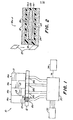
- the forage harvester has a cutting device 10 which has a shear bar 12 and four rotating cutting heads 14a, 14b, 14c and 14d. Each cutting head in turn has a plurality of knives or blades 13. Corresponding to the four cutting heads, four proximity sensors 16a, 16b, 16c and 16d are also provided in the new monitoring device. Each proximity sensor is arranged in a bore that extends through the shear rod 12.
- each proximity sensor 16 comprises a permanent magnet 18, which is arranged at one end of a ferromagnetic or magnetically conductive rod 20.
- a sensor winding 22 coaxially surrounds the rod 20.
- the magnet 18 and the rod 20 are arranged in a hollow cylindrical plastic housing 24 which is fastened to a bore 26 in the shear rod 12.
- the outer end of the mag Neten 18 is preferably flush with the end face of the shear bar 12, namely at the point 13 initially located. Movement of each blade 13 past the proximity sensor 16 results in the generation of an electrical signal Vs which appears as a voltage across the terminals of the winding 22.
- the output terminals of the four proximity sensors are connected in a monitor circuit.
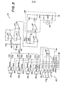
- the monitor circuit 30 can generate output signals containing information regarding the distance between the knife and the shearbar from one or more selected cutter heads 14a, 14b, 14c and 14d. This information is displayed to the driver by a display panel 34.
- the monitor circuit 30 comprises four identical signal evaluation circuits 40a, 40b, 40c and 40d. Each of these evaluation circuits is connected to the winding connections of an associated proximity switch.
- each evaluation circuit 40 has a resistor R1, which is connected to a connection of the sensor winding and to the common connections of the resistors R2 and R3 and via a filter capacitor C1.
- the other connection of the sensor winding 22 is connected to the output and to the (-) input of an isolating amplifier 42 and to the (+) input of a working amplifier 44.
- the (+) input of the amplifier 42 is with a reference voltage Vref of, for example. 1.2 volts DC connected.
- the output of amplifier 42 is grounded via a capacitor C2 and connected to the anode of a diode D1 and to the (-) input of a comparator 46 via resistor R4.
- the cathode of the diode Dl is connected to the other terminal of the resistor R3 and to the (+) input of the comparator 46.
- the (-) input of comparator 46 is in turn grounded through resistor R5.
- the other terminal of resistor R2 is connected to the (-), - input of amplifier 44.
- the (-) input of amplifier 44 is also connected to the source (S) and substrate (SUB) terminals of a field transistor (FET) 45 via resistor R6.
- the (-) input and the output of the amplifier 44 are connected to one another by a resistor R7 and an integration capacitor C3 lying in parallel therewith.
- the output of amplifier 44 is also connected to the drain port (D) of field transistor 45 and to the (+) input of a variable gain amplifier 48.
- the gate (G) of field transistor 45 is grounded via a capacitor C4 and connected via a resistor R8 to a terminal 47, which in turn is connected to the output of a comparator 46.
- the gate (G) of field transistor 45 is also connected to the anode of a diode D2 via resistor R9. The cathode of this diode D2 is connected to the connection 47.
- a resistor R10 is between the reference voltage at the outlet of the isolation amplifier 42 and the (-) input of the amplifier 48. This comprises a variable resistor R11 between the terminal 49 and its (-) input. By changing the resistance R11, the amplification factor of the amplifier 48 can be changed in order to adapt to variations in the signal strength at the proximity sensors 16a, 16b, 16c and 16d due to changes in the proximity sensors themselves or due to changes in their mounting position.
- the output of amplifier 48 is connected to terminal 49 and to the input terminal of a CMOS switch.
- the output terminal of this switch 50 is connected to the (+) input of an isolation amplifier 52 with a constant gain factor via resistor R13.
- the (+) input of the isolating amplifier 52 is grounded via a capacitor C6, which is used to form an average value.
- the (-) input of the isolation amplifier 52 is connected to its output. The high impedance of the isolating amplifier 52 prevents the capacitor C6 from being discharged through the output line 53 of the evaluation circuit 40.
- connection 47 is connected to the A input of a monostable multivibrator 56.
- the multivibrator 56 generates a relatively short positive or ready pulse at the Q output, the pulse lasting a little less than 1 millisecond.
- the multivibrator is triggered by the transition from a low to a high value at the output of the comparator 46.
- the Q output of the multivibrator 56 is connected to the connection 55 and to the input of the AND gate 58 of a logic circuit 57.
- the other input of gate 58 is connected to the output of an OR gate 60.
- Control switching lines 62 and 64 are connected to the inputs of gate 60.
- the output of the AND gate 58 is connected to the control input C of the COMS switch. The switch is open as long as the output of gate 58 is low and is closed when the output on gate 58 is high.
- FIG. 3 shows that the output lines 53a-53d of the evaluation circuits 40a-40d are each connected to the anode of an associated diode D3a-D3d.
- the cathodes of the diodes D3a-D3d are connected together and connected to the (+) input of an isolation amplifier 70 with a constant gain factor via the line 68.
- the (+) input of amplifier 70 is grounded through resistor R15.
- a variable offset voltage Vos is tapped by a potentiometer R16, which lies between a voltage source + Vcc (for example of +8 volts DC) and ground. This offset voltage is applied to the (+) input of an isolating amplifier 72 with a fixed gain factor. The output of the isolation amplifiers 70 and 72 is connected to their respective (-) input.
- the voltages Vmax and Vos are fed to the (+) and (-) inputs of a differential amplifier 74 with a constant gain factor.
- the output voltage Vd of the differential amplifier 74 is applied to the (+) input of a variable gain amplifier 76, the gain of which can be set, for example, between 1 and 6 by changing the variable resistor R17 which is between the (-) input and the output of the gain factor 76.
- the (-) input of amplifier 76 is grounded through resistor R18.
- the output voltage Vo of the amplifier 76 is connected to a measuring driver circuit 80.
- This comprises a working amplifier 82, the (+) input of which is connected to the output of the amplifier 76.
- the output of amplifier 82 is connected to the base of a 2N222 transistor Q2.
- the collector of this transistor is connected to the voltage source + Vcc.
- the emitter of the Transistor is connected to the (-) input of operational amplifier 82 and to the anode of diode D4.
- the cathode of this diode D4 is connected to earth via resistor R19.
- a conventional, analog voltmeter 84 is connected in parallel with the resistor R19. It would also be possible to provide a digital display device (not shown) instead of the voltmeter 84 if the output signal Vo is converted by corresponding analog / digital converters.
- the switch module 32 is preferably mounted in the driver's cab and comprises four switches 5a-5d. One side of each switch is connected to the voltage source + Vcc. The other side of each switch 5a-5d is connected to the respective input of a NOR gate 92 of a logic circuit 94. The inputs of gate 92 are connected to ground via identical resistors R20a-R20d. The inputs of the gate 92 are also connected to control lines 62a-62d from logic circuits 57 of the evaluation circuits 40a-40d. The output of gate 92 is connected to control lines 64a-64d of logic circuit 57.
- each of the four evaluation circles 40a-40d can be connected to a corresponding circle of four identical circles 200a-200d, one of which is shown, for example, in FIG. 6.
- Each of these circles 200a-200d includes a worn or misaligned blade detector unit 202, a missing or broken blade detector unit 204 and a unit 206 which determines whether corresponding proximity sensors 16a-16d have become ineffective.
- Each of the circuits 200a-200d comprises a monostable multivibrator 208 with a grounded A input and a B input, which is connected to the connection 47 of the evaluation circuit 40 for receiving the voltage Vb.
- the multivibrator 208 generates a positive pulse at its Q output, the duration of which is equal to the duration of the working period of the multivibrator 56 of the evaluation circuit 40, depending on the transition from high values to low values of the voltage Vb.
- Each unit 202 includes a CMOS switch 210 with an input terminal connected to the terminal 49 of the evaluation circuit 40 to receive the amplified integrated capacitor voltage Vc.
- the control input C of the switch 210 is connected to the connection 55 of the evaluation circuit 40.
- the output terminal of switch 210 is connected to ground through a selection capacitor C7.
- the output of switch 210 is also connected to the input of a single gain amplifier 212 and to the anode of the first (D5) of two diodes D5 and D6 connected in series.
- the cathode of diode D6 is grounded through resistor R21 and connected to the (+) input of comparator 214.
- the output of the isolation amplifier 212 is connected to the input terminal of the CMOS switch 216, whose control C inlet is connected to the Q outlet of the monostable multivibrator 208.
- the output terminal of switch 260 is grounded through a selection capacitor C8 and connected to the (-) inlet of comparator 214.
- the isolation amplifier 212 provides isolation between the select capacitors C7 and C8 to prevent the voltage of the capacitor C8 from affecting the voltage on the capacitor C7.
- Each unit 204 comprises an inverter 220, one inlet of which is connected to the connection 47 of the evaluation circuit 40 for receiving the voltage Vb.
- the outlet of the Inverter 220 is connected to the base of a transistor Q3 via resistor R22.
- the base of this transistor is grounded through capacitor C9.
- the emitter of transistor Q3 is grounded, while the collector is connected to the voltage source + Vcc through resistor R23, to the (+) input of fixed gain isolation amplifier 222, and to ground through capacitor C10.
- the collector of transistor Q3 is connected to the anode of two diodes D7 and D8 in series.
- the cathode of diode D8 is grounded via resistor R24 and connected to the (+) input of comparator 224.
- isolation amplifier 222 is connected to its (-) inlet and to the inlet port of another CMOS switch 226.
- Control port C of switch 226 is connected to the Q output of monostable multivibrator 208.
- the output port of switch 226 is through the Selection capacitor C11 is grounded and connected to the (-) inlet of comparator 224.
- the outlet of this comparator is connected to output line 208.
- Each unit 206 includes an inverter 230 which is connected to the terminal 47 for receiving the voltage Vb.
- the output of inverter 230 is connected to one side of a capacitor C12 via resistor R25.
- the other side of the capacitor C12 is connected to the base of a transistor Q4 and to the cathode of the diode D9.
- the anode of this diode and the emitter of the transistor are grounded.
- the collector of transistor Q4 is connected to voltage source Vcc through resistor R26, to ground through capacitor C13, and to the inlet of a reverse Schmitt trigger 232.
- the outlet of this trigger 232 is connected to the output line 234 and via an inverter 238 to an output line 236.
- the output lines 218, 228, 234 and 236 of the circuits 200a-200d are connected to corresponding inlets of the circuits 240 and 260 in FIGS. 7 and 8, respectively.
- Circuit 240 of FIG. 7 includes a multiple input NOR gate 242. Four of these inputs are connected to corresponding output lines 218a-218d of units 202a-202d of circuits 200a-200d. Another four of the inputs of the gate are connected to corresponding output lines 228a-228d of the units 204a-204d of the circuits 200a-200d.
- the output of gate 242 is connected to the B input of a monostable multivibrator 244, the A inlet of which is grounded.
- the multivibrator 244 generates a positive pulse of predetermined duration at the Q output depending on the transitions from high values to low values at the B input.
- the Q output is connected to a lamp driver circuit 246. This can be a cascaded double transistor current amplifier, which in turn controls lamps or other indicators 248 on the display panel 34 when the Q output of the multivibrator 244 is high.
- Circuit ' 260 in Figure 8 includes an OR gate 262. Each inlet is connected to units 206 of circuits 200a-200d via a corresponding output line 234a-234d. Circuit 260 includes another OR gate 264, the two inputs of which are connected to corresponding output lines 236a-236d of units 206 of circuits 200a-200d.
- the outlets of gates 262 and 164 are connected to the inlets of an AND gate 266, the outlet of which is connected to the base of a transistor Q5.
- the collector of the transistor is connected to the voltage source + Vcc.
- the emitter of the transistor is connected to the inlet of a lamp driver circuit 272, which is similar to that Driver circuit 246 can be formed.
- driver circuit 272 The connection is made via resistor R27 also with the cathode of a diode D10 and via resistor R28 with earth.
- the inlet of driver circuit 272 is connected to the anode of diode D10 and to capacitor C14.
- a Schmitt trigger can be arranged between R27 and the driver circuit 272. Its hysteresis can prevent the driver circuit 272 from operating unstably if the voltage on the capacitor C40 is close to the limit level of the driver circuit 272.
- the driver circuit drives a lamp or other display device 274 on the display board 34.
- the display panel 34 in FIG. 1, which includes lamps and meters 84 and lamps 248 and 274, can be assembled so that it is visible to the operator when in his cab, not shown , so that the play between the knives and the shear bar can be easily monitored during the operation of the forage harvester. It could also be desirable to mount the indicator 32 so that it is also visible from a position the driver assumes when adjusting or adjusting the play of the shear bar, e.g. after sharpening the knives. This would be e.g. Accessible with a movable display board or with separate display boards that are arranged so that they are also visible from the setting position. In this way, the operator or the driver can use the display device to use the measured values when adjusting the position of the shear bar after the sharpening process.
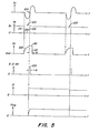
- the monitoring device works as follows: The movement of a knife 13 of one of the cutting heads 14a-14d in the vicinity of the associated An Proximity sensor 16a-16d interferes with the magnetic field generated by the permanent magnet 18. The change in the magnetic field leads to a sensor voltage Vs across the sensor winding 22, as best shown in FIG. 5. When the blade 13 moves away from the proximity sensor 16, the polarity of this voltage Vs is reversed from the polarity during the approach. The voltage Vs therefore reverses its polarity so that its magnitude is neutral with respect to a reference voltage Vref at the moment when the distance between the blade 13 and the proximity sensor 16 is at a minimum in a direction along the axis of the winding 22.
- the normally high voltage Vb at the output of the comparator 46 and at the terminal 47 is low, as shown at point 100 in Fig. 5, as long as the voltage Vs is less than the reference voltage Vref.
- the low level of voltage Vb turns off field transistor 45 so that amplifier 44 can charge integration capacitor C3 to a value as shown at 102.
- the peak voltage Vs generated by proximity sensor 16 is a function of the air gap to be measured, the speed of the moving knife, and other constant factors, such as the field strength of the magnet, the number of turns of the windings 22, of different impedances and also geometrical arrangements.
- the voltage Vs at a low knife speed has a relatively lower amplitude but a relatively longer duration.
- the voltage Vs at higher knife speeds has a larger amplitude but a shorter duration.
- the area under the time-voltage curve Vs in FIG. 5 is essentially only a function of the smallest distance or gap between the knife 13 and the proximity sensor 16.
- the voltage Vc across the capacitor C3 is thus an integration function the sensor voltage Vs and is therefore characteristic of the smallest distance between the blade and the proximity sensor.
- the output voltage Vb switches from a low value to a high value, as indicated at point 106.
- This transition of the voltage Vb triggers the monostable multivibrator 56.
- This pulse closes the normally open CMOS switch 50 for a corresponding period of time via the AND gate 58.
- the switch 50 is closed, the voltage Vf corresponds to the peak value of the voltage Vc.
- the voltage Vf arrives at the average capacitor C6 via resistor R13.
- the resistor R9 preferably has an impedance which is substantially smaller than that of the resistor R8, so that the capacitor C4 can quickly discharge through the resistor R8 and the diode D4 to the field transistor 45 depending on the Switch off occurrence of the transition from high to low of the voltage Vb, as indicated at 114.
- each evaluation circuit 40a-40d produces an average output voltage Vave (a) - (d) in the manner just described to represent an average minimum gap between the blade and proximity sensor of the corresponding cutting heads 14a-14d .
- a diode network formed by diodes D3a-D3d generates a voltage Vmax on line 68 which is equal to the highest value of the voltages Vave (a) - (d) less the small voltage drop of 0.7 Volts on the diode.
- a constant gain differential amplifier 74 generates a differential voltage Vd which is equal to the difference between the separated voltages Vmax and the offset voltage Vos.
- the differential voltage Vd is amplified by an amplifier 76 with a variable gain factor in order to obtain an output voltage Vo which is fed to the driver circuit 80 for the measuring device 84.
- the measuring device 84 thus generates a recognizable or perceptible signal which corresponds to the average distance between the blade and the proximity sensor of the cutting head or cutting segment 14, which shows the lowest average separation between the blade and the proximity sensor.
- the output of the OR gate 60 of the evaluation circuit 40a remains high, so that the pulse of the monostable multivibrator now periodically closes the switch 50 via the AND gate, so that a voltage Vave ( a) appears at the output 53a of the evaluation circuit 40a, which does not have the value zero.
- the voltage Vmax in the line 68 thus only represents the voltage Vave (a) and the measuring device 84 displays a value which corresponds only to the cutting head 14a.
- any combination of circuits 40a-40d can be disabled by opening or closing a corresponding combination of switches 5a-5d.
- the display device 84 always shows a value which reflects the average separation between the knife and the proximity sensor of the cutting segment, which corresponds to the cutting segment with the smallest distance, specifically with reference to the circles 40a brought into effect -40d.
- Each unit 202 operates as follows: The voltage Vc generated by the movement of the first blade 13 is selected and from the capacitor C7, triggered by a trigger pulse of the Q output of the monostable multivibrator 56, which pulse begins with the transition from low to high voltage Vb. On the next transition from high to low voltage Vb caused by the movement of second blade 13, the output pulse of monostable multivibrator 208 momentarily closes CMOS switch 216 so that the first selected voltage on capacitor C7 is transferred to capacitor C8 and is held there. The voltage Vc corresponding to the second blade is then selected and held on capacitor C7 at the next transition from voltage Vb from low to high.
- Each unit 204 operates as follows: During normal operation, the transitions or negative pulses 105 of the voltage Vb at the output of the comparator 46 of each evaluation circuit 40a-40d and the standby pulses, as indicated at 108 in Fig. 5, cause alternating charging and Discharge of the integration capacitor C3 every time a blade 13 passes one of the proximity sensors 16a-16d. These periodically occurring negative pulses of voltage Vb are characterized by receive inverter 220 of unit 204 to periodically turn on transistor Q3 when the value of Vb is low so that capacitor C10 is periodically discharged. However, capacitor C10 is periodically charged through resistor R23 during the period during which the value of Vb between the negative pulses of Vb is large when Q3 is off.
- capacitor C10 Before each discharge of the capacitor C10, its voltage is held by the capacitor C11 via the switching operation of the CMOS switch 226 and the monostable multivibrator 208 in a manner similar to that with the successive voltage signals from the capacitors C7 and C8 in the unit 202. After the voltage of capacitor C10 is transferred to capacitor C11 and capacitor C10 is discharged, the low to high voltage Vb transition turns off transistor Q3 and allows capacitor C10 to be recharged to a new voltage.
- the old voltage on capacitor C11 and the new voltage on capacitor C10 are compared using comparator 224, whose normally low output at 228 only goes high, if the new voltage on capacitor C10 (minus 1.4 volts) is greater than the old voltage on capacitor C11. If there are no negative pulses from voltage Vb, periodically discharging capacitor C10 prevents the new voltage from becoming high enough to step up the output of comparator 224. However, if a negative pulse of the voltage Vb is not generated by the comparator 46 due to some malfunction, for example if one blade is missing completely or there are several broken blades or if an electrical malfunction occurs, then the transistor Q3 is not turned on. In this case, the charging of the capacitor C10 continues and a new voltage arises, which may be greater than the old voltage at the capacitor C11 plus 1.4 volts. In this way, the output of comparator 224 is switched to high values depending on this malfunction.
- Circuit 240 operates as follows: During normal operations, all inputs 218a-218d and 228a-228d leading to NOR gate 242 are low. The output of this gate is high, the Q output of the monostable multivibrator 244 is low, and the lamp or indicator 248 is in its inactive state. However, if any of the blades 13 are worn, misaligned, missing, or broken, then those of the inputs 218a-218d and 228a-228d assume a high value due to the functions of the previously described units 202 and 204. If any one of the inputs of gate 242 takes the high value, then the output of the gate changes from high to low.
- This pulse causes the driver circuit 246 to activate the lamp or indicator 248 and produce a visual indication or other perceptible signal so as to warn the operator that there is a worn, improperly adjusted, or missing blade or broken blade condition .
- Each unit 206 and associated circuit 260 operate as follows: when voltage Vb is high, transistor Q4 is turned off and capacitor C13 slowly charges through the relatively high impedance of resistor R26. However, during normal operation, capacitor C13 is periodically discharged through transistor 04, which is discharged depending on the negative pulses of voltage Vb shown in FIG. 5 in FIG. 5. This prevents the capacitor C13 from being charged so high that it triggers the Schmitt trigger 232. Remain during normal working thus all output lines 234a-234d of circuits 200a-200d at high values and all output lines 236a-236d of circuits 200a-200d at low values. While all lines 234a-234d are high, the output of OR gate 262 is high.
- OR gate 264 When all lines 236a-236d are low, the output of OR gate 264 is low. In this state, the OR gate 264 is low and the AND gate 266 is high, so that the transistor Q5 is switched off and the driver circuit 272 for the lamp 274 is switched off.
- the units 206 and circuit 260 thus cooperate to generate a warning signal when one or some but not all of the proximity sensors 16a-16d are operating, but prevent the generation of a misleading warning signal when all the proximity sensors 16a-16d are inactive due to the lack of rotation of the cutting heads 10.
Landscapes
- Life Sciences & Earth Sciences (AREA)
- Forests & Forestry (AREA)
- Engineering & Computer Science (AREA)
- Mechanical Engineering (AREA)
- Environmental Sciences (AREA)
- Measurement Of Length, Angles, Or The Like Using Electric Or Magnetic Means (AREA)
- Cable Accessories (AREA)
- Shearing Machines (AREA)
- Component Parts Of Construction Machinery (AREA)
- Turning (AREA)
- Length Measuring Devices With Unspecified Measuring Means (AREA)
- Pinball Game Machines (AREA)
- Harvester Elements (AREA)
- Threshing Machine Elements (AREA)
- Guiding Agricultural Machines (AREA)
- Harvesting Machines For Root Crops (AREA)
- Transmission And Conversion Of Sensor Element Output (AREA)
Abstract
Es ist eine Einrichtung an Futtererntemaschinen mit mehreren Annäherungsfühlern vorgesehen, die auf die Annäherung von Messers eines Scherkopfes an eine gestellfeste Scherstange ansprechen. Die Annäherungssignale werden umgewandelt und ausgewertes. Unabhängig davon ist eine Warneinrichtung mit einem zweiten Steuerkreis vorgesehen, dem die bei der Auswertung erzeugten Impulssignale zugeführt werden. Der Steuerkreis spricht dabei darauf an, ob alle Annäherungsfühler in Betrieb sind oder alle Annäherungsfühler keine Signale senden bzw. ob einer oder mehrere Annäherungsfühler entsprechende Signale senden während das Signal von einem weiteren Annäherungsfühler ausbleibt.A device is provided on forage harvesting machines with several proximity sensors, which respond to the approach of a shaving head knife to a frame-fixed shear bar. The proximity signals are converted and evaluated. Independently of this, a warning device is provided with a second control circuit, to which the pulse signals generated during the evaluation are fed. The control circuit responds to whether all proximity sensors are in operation or all proximity sensors are not sending any signals or whether one or more proximity sensors are sending corresponding signals while the signal from another proximity sensor is missing.
Description
Die Erfindung betrifft eine Einrichtung, insb. an Futtererntemaschinen, mit einer Mehrzahl von Annäherungsfühlern, die jeweils in Bezug auf die Scherstange fest und nahe eines von mehreren, jeweils mehrere Schneidmesser aufweisenden Schneidkopfes angeordnet sind und ein Annäherungssignal erzeugen, das der Annäherung eines Schneidmessers an die Scherstange entspricht mit den Merkmalen des Oberbegriff des Anspruchs 1.The invention relates to a device, in particular on forage harvesting machines, with a plurality of proximity sensors, each of which is fixed with respect to the shear bar and is arranged close to one of a plurality of cutting heads, each having a plurality of cutting knives, and generates an approximation signal which indicates the approach of a cutting knife to the Shear bar corresponds with the features of the preamble of
Eine solche Einrichtung ist aus der DE-A-29 43 828 bekannt. Bei dieser sind Annäherungsfühler in Ausnehmungen der Scherstange eingesetzt, die ein Magnetfeld erzeugen, welches durch die sich vorbeibewegenden Schneidmesser des schneidkopfes verändert wird. Das durch den Annäherungsfühler erzeugte Signal wird einem Auswertekreis zugeführt, in welchem das Signal während der Durchlaufzeit integriert und mit voreingestellten Schwellwerten vergleichen wird. Eine Detektoreinrichtung erfaßt den größten Wert des Integrierten Signals und erzeugt ein dem minimalen Abstand zwischen der Scherstange und den Schneidmessern proportionales Signal. Dieses wird durch ein Meßinstrument zur Anzeige gebracht. Weiter wird der mittlere Abstand zwischen den Messern und der Scherstange dadurch festgestellt, daß die Ausgangsspannung der Integrationseinrichtung einem Tiefpaßfilter zugeführt wird dessen Ausgangssignal ebenfalls an dem Meßinstrument zur Anzeige gebracht wird. Es ist ein weiterer Detektor vorgesehen, der mit dem Ausgang der Integrationseinrichtung über eine Abtast- und Halteschaltung verbunden ist, um den größten Abstand zwischen den Messern und der Scherstange festzuhalten. Dabei werden über die Schaltung die Abstände aller aufeinanderfolgender Messer in Form eines abgestuften Signals wiedergegeben. Auf diese Weise ist es möglich mit der bekannten Einrichtung die unterschiedlichen Abstände der verschiedenen Messer des Schneidkopfes sowie bei einem einzelnen Messer Abstandsänderungen entlang der Messerlänge zu erfassen. Insgesamt können der Abstand des den geringsten Abstand aufweisenden Messers, der Abstand des den größten Abstand aufweisen- den Messers, der mittlere Abstand aller Messer und ggf. bei Einsatz mehrerer Meßfühler die Änderung des Abstandes entlang der Länge eines Messers bestimmt werden. Die Anzeige der Abstände erfolgt dabei unabhängig von der Drehgeschwindigkeit, unabhängig von der Anzahl der Messer, unabhängig von der Messerabnutzung und unabhängig von der Messergeometrie. Die Einrichtung kann eingesetzt werden, um während des Betriebes eine Nachstellung der Messer und damit die Aufrechterhaltung günstiger Schneidbedingungen zu gewährleisten.Such a device is known from DE-A-29 43 828. In this case, proximity sensors are used in recesses in the shear rod, which generate a magnetic field which is changed by the cutting blades of the cutting head moving past. The signal generated by the proximity sensor is fed to an evaluation circuit in which the signal is integrated during the cycle time and compared with preset threshold values. A detector device detects the greatest value of the integrated signal and generates a signal proportional to the minimum distance between the shear bar and the cutting blades. This is displayed by a measuring instrument. Furthermore, the average distance between the knives and the shear bar is determined by the output voltage of the integration device being fed to a low-pass filter, the output signal of which is also displayed on the measuring instrument. A further detector is provided which is connected to the output of the integration device via a sample and hold circuit in order to record the greatest distance between the knives and the shear bar. The distances of all successive knives are reproduced in the form of a graduated signal via the circuit. In this way it is possible with the known device to detect the different distances between the different knives of the cutting head and, in the case of a single knife, changes in distance along the knife length. Overall, the distance of the one with the smallest distance Knife, the distance of the knife having the greatest distance, the mean distance of all knives and, if necessary, the use of several sensors to determine the change in the distance along the length of a knife. The distances are displayed regardless of the speed of rotation, regardless of the number of knives, regardless of knife wear and regardless of the knife geometry. The device can be used to ensure readjustment of the knives during operation and thus the maintenance of favorable cutting conditions.
Es ist Aufgabe der Erfindung, eine Einrichtung mit den Merkmalen des Oberbegriffs des Anspruchs 1 so weiterzu- bilden, daß die Funktionstüchtigkeit der Annäherungs fühler automatisch überwacht werden kann.It is an object of the invention to develop a device with the features of the preamble of
Diese Aufgabe wird durch die Maßnahmen des Anspruchs 1 gelöst.This object is achieved by the measures of
Der besondere Vorteil liegt unter anderem darin, daß eine von der Anzeigeeinrichtung unabhängige Warneinrichtung vorgesehen ist, die durch einen gesonderten Kreis gesteuert wird. Dieser gesonderte Kreis spricht dabei darauf an, ob eines oder mehrere der von den Komparatoreinrichtungen kommenden Impulse erzeugt oder nicht erzeugt wird, und zugleich-. auch anzuzeigen vermag, wenn von keiner der Komparatoreinrichtungen ein Impuls geliefert wird.The particular advantage is, inter alia, that a warning device which is independent of the display device and is controlled by a separate circuit is provided. This separate circuit responds to whether one or more of the pulses coming from the comparator devices is generated or not, and at the same time. can also indicate if none of the comparator devices delivers a pulse.
Hierdurch ist eine zuverlässige Überwachung der Funktionstüchtigkeit der Annäherungsfühler möglich. Gleichzeitig wird unterbunden, daß die Warneinrichtung anspricht, wenn die Signale von allen Annäherungsfühlern fehlen, wie dies z.B. beim Starten der Maschine der Fall sein kann.This enables reliable monitoring of the functionality of the proximity sensors. At the same time, it is prevented that the warning device responds if the signals from all proximity sensors are missing, e.g. may be the case when starting the machine.
Vorteilhafterweise ist die Anordnung gemäß Anspruch 2 weitergebildet. Dadurch wird dem Fahrer die Möglichkeit einer Überprüfung nur eines bestimmten Schneidelementes ermöglicht. Bei Auftreten eines Warnsignales kann somit der Fahrer leicht überprüfen, welcher der Annäherungsfühler gestört ist.The arrangement is advantageously further developed according to
Damit können Störungen in der Funktionsweise der Futtererntemaschine frühzeitig erkannt und abgeschaltet werden, wobei die Fehleranalyse außerordentlich einfach und zuverlässig ist. Die Totzeiten der Maschine können so außerordentlich gering gehalten werden.This enables malfunctions in the functioning of the forage harvester to be recognized and switched off at an early stage, the error analysis being extremely simple and reliable. The machine's dead times can be kept extremely low.
Die Erfindung wird nachfolgend anhand schematischer Zeichnungen an einem Ausführungsbeispiel näher erläutert.The invention is explained in more detail below with the aid of schematic drawings using an exemplary embodiment.
Es zeigen:
Figur 1 eine schematische Gesamtansicht einer Maschine mit einer Überwachungseinrichtung gemäß der Erfindung mit Draufsicht auf die zugehörigen Schneidelemente, die Scherstange und die An- näherungsfühler.Figur 2 in größerem Maßstabe einen Querschnitt entlang der Schnittlinie II-II derFigur 1;- Figur 3 ein Schaltdiagramm des gesamten Fühl-, Auswertungs- und Anzeigekreises;
- Figur 4 ein detailliertes Schaltbild eines Auswertungskreises, wie er für jeden Annäherungsfühler vorgesehen ist;
- Figur 5 eine grafische Darstellung der Impulsformen von Signalen an verschiedenen Stellen des Schaltkreises und
Figur 6,7 und 8 weitere Schaltdiagramme von Kreisen, die wahlweise an den Kreis nach Fig. 4 angeschlossen werden können.
- Figure 1 is a schematic overall view of a machine with a monitoring device according to the invention with a plan view of the associated cutting elements, the shear bar and the proximity sensors.
- Figure 2 on a larger scale a cross section along the section line II-II of Figure 1;
- Figure 3 is a circuit diagram of the entire sensing, evaluation and display circuit;
- FIG. 4 shows a detailed circuit diagram of an evaluation circuit as it is provided for each proximity sensor;
- Figure 5 is a graphical representation of the pulse shapes of signals at various points in the circuit and
- FIGS. 6, 7 and 8 show further circuit diagrams of circuits which can optionally be connected to the circuit according to FIG. 4.
Bei der nachfolgenden Beschreibung wird davon ausgegangen, daß die Futtererntemaschine eine Schneideinrichtung 10 aufweist, welche eine Scherstange 12 sowie vier rotierende Schneidköpfe 14a,14b,14c und 14d aufweist. Jeder Schneidkopf weist seinerseits mehrere Messer oder Klingen 13 auf. Entsprechend den vier Schneidköpfen sind bei der neuen überwachungseinrichtung auch vier Annäherungsfühler 16a, 16b, 16c und 16d vorgesehen. Jeder Annäherungsfühler ist in einer Bohrung angeordnet die sich durch die Scherstange 12 erstreckt.In the following description it is assumed that the forage harvester has a
Wie am Besten aus Fig.2 hervorgeht umfaßt jeder Annäherungsfühler 16 einen Permanentmagneten 18, der an einem Ende einer ferromagnetischen oder magnetisch leitenden Stange 20 angeordnet ist. Eine Fühlerwicklung 22 umgibt die Stange 20 koaxial. Der Magnet 18 und die Stange 20 sind in einem hohlen zylindrischen Kunststoffgehäuse 24 angeordnet, das einer Bohrung 26 in der Scherstange 12 befestigt ist. Das äußere Ende des Magneten 18 liegt vorzugsweise bündig mit der Stirnfläche der Scherstange 12,und zwar an der den Klingen 13 zunächst gelegenen Stelle. Die Bewegung jeder Klinge 13 vorbei an dem Annäherungsfühler 16 führt zur Erzeugung eines elektrischen Signals Vs, das als Spannung über den Anschlüssen der Wicklung 22 auftritt.As best shown in FIG. 2, each proximity sensor 16 comprises a
Wie aus Fig. 1 hervorgeht sind die Ausgangsanschlüsse der vier Annäherungsfühler in einem Monitorkreis verbunden. In Abhängigkeit vom Zustand eines durch die Bedienungsperson zu betätigenden Schaltmoduls 32, das in einer für die Bedienungsperson zugänglichen Stellung, z.B. in der Fahrerkabine (nicht gezeigt) nahe der Schneideinrichtung 10 montiert ist, kann der Monitorkreis 30 Ausgangssignale erzeugen, welche eine Information bezüglich des Abstandes zwischen Messer und Scherstange von einem oder mehreren ausgewählten Schneidköpfen 14a, 14b, 14c und 14d enthält. Diese Information wird für den Fahrer durch eine Anzeigetafel 34 angezeigt. Diese umfaßt ein Analogmeßgerät oder eine digitale Anzeige sowie Lampen oder andere Anzeigevorrichtungen.As shown in Fig. 1, the output terminals of the four proximity sensors are connected in a monitor circuit. Depending on the condition of a
Der Monitorkreis 30 umfaßt nach Fig. 3 vier identische Signalauswertungskreise 40a, 40b, 40c und 40d. Jeder dieser Auswertungskreise ist an die Wicklungsanschlüsse eines zugehörigen Annäherungsschalters angeschlossen.According to FIG. 3, the
Aus Fig. 4 ist ersichtlich, daß jeder Auswertungskreis40 einen Widerstand R1 aufweist, der mit einem Anschluß der Fühlerwicklung und an die gemeinsamen Anschlüsse der Widerstände R2 und R3 sowie über einen Filterkondensator C1 verbunden ist. Der andere Anschluß der Fühlerwicklung 22 ist mit dem Ausgang und mit dem (-)-Eingang eines Trennverstärkers 42 und mit dem (+)-Eingang eines Arbeitsverstärkers 44 verbunden. Der (+)-Eingang des Verstärkers 42 ist mit einer Bezugsspannung Vref von zB. 1,2 Volt Gleichspannung verbunden.From Fig. 4 it can be seen that each evaluation circuit 40 has a resistor R1, which is connected to a connection of the sensor winding and to the common connections of the resistors R2 and R3 and via a filter capacitor C1. The other connection of the sensor winding 22 is connected to the output and to the (-) input of an
Der Ausgang des Verstärkers 42 ist über einen Kondensator C2 geerdet und mit der Anode einer Diode Dl und mit dem (-)-Eingang eines Komparators 46 über Widerstand R4 verbunden. Die Katode der Diode Dl ist mit dem anderen Anschluß des Widerstandes R3 und mit dem (+)-Eingang des Komparators 46 verbunden. Der (-)-Eingang des Komparators 46 ist seinerseits über Widerstand R5 geerdet. Der andere Anschluß des Widerstandes R2 ist mit dem (-),-Eingang des Verstärkers 44 verbunden. Der (-)-Eingang des Verstärkers 44 ist außerdem mit dem Quell-(S) und Substratanschlüssen (SUB) eines Feldtransistors (FET) 45 über Widerstand R6 verbunden. Der (-)-Eingang und der Ausgang des Verstärkers 44 sind miteinander durch einen Widerstand R7 und einen parallel dazu liegenden Integrationskondensator C3 verbunden. Der Ausgang des Verstärkers 44 ist außerdem mit dem Abflußanschluß (D) des Feldtransistors 45 und mit dem (+)-Eingang eines Verstärkers 48 mit variablem Verstärkungsfaktor verbunden.The output of
Das Gatter (G) des Feldtransistors 45 ist über einen Kondensator C4 geerdet- und über einen Widerstand R8 mit einem Anschluß 47 verbunden, der seinerseits mit dem Ausgang eines Komparators 46 verbunden ist. Das Gatter (G) des Feldtransistors 45 ist außerdem mit der Anode einer Diode D2 über Widerstand R9 verbunden. Die Katode dieser Diode D2 ist an den Anschluß 47 gelegt.The gate (G) of field transistor 45 is grounded via a capacitor C4 and connected via a resistor R8 to a terminal 47, which in turn is connected to the output of a
Ein Widerstand R10 liegt zwischen der Bezugsspannung am Auslaß des Trennverstärkers 42 und dem (-)-Eingang des Verstärkers 48. Dieser umfaßt einen variablen Widerstand R11 zwischen dem Anschluß 49 und seinem (-)-Eingang. Durch Veränderung des Widerstandes R11 kann der Verstärkungsfaktor des Verstärkers 48 verändert werden, um eine Anpassung an Variationen der Signalstärke an den Annäherungsfühlern 16a, 16b, 16c und 16d aufgrund.von Veränderungen in den Annäherungsfühlern selbst bzw. aufgrund Veränderungen ihrer Montagestellung zu ermöglichen.A resistor R10 is between the reference voltage at the outlet of the
Der Ausgang des Verstärkers 48 ist mit dem Anschluß 49 und mit dem Eingangsanschluß eines CMOS-Schalters verbunden. Der Ausgangsanschluß dieses Schalters 50 ist mit dem (+)-Eingang eines Trennverstärkers 52 mit konstantem Verstärkungsfaktor über Widerstand R13 verbunden. Der (+)-Eingang des Trennverstärkers 52 ist über einen zur Bildung eines Mittelwertes dienenen Kondensators C6 geerdet. Der (-)-Eingang des Trennverstärkers 52 ist an seinen Ausgang angeschlossen. Die hohe Impedanz des Trennverstärkers 52 verhindert, daß der Kondensator C6 durch die Ausgangsleitung 53 des Auswertungskreises 40 entladen wird.The output of
Der Anschluß 47 ist mit dem A-Eingang eines monostabilen Multivibrators 56 verbunden. Der Multivibrator 56 erzeugt einen relativ kurzen positiven oder Bereitschaftsimpuls am Q-Ausgang, wobei der Impuls ein wenig kürzer als 1 Millisekunde dauert. Dabei wird der Multivibrator durch den von einem niedrigen zu einem hohen Wert laufenden Übergang am Ausgang des Komparators 46 ausgelöst.The
Der Q-Ausgang des Multivibrators 56 ist an den Anschluß 55 und an den Eingang des UND-Gatters 58 eines logischen Kreises 57 angeschlossen. Der andere Eingang des Gatters 58 ist mit dem Ausgang eines ODER-Gatters 60 verbunden. Steuerschaltleitungen 62 und 64 sind an die Eingänge des Gatters 60 angeschlossen. Der Ausgang des UND-Gatters 58 ist mit dem Kontrolleingang C des COMS-Schalters verbunden. Der Schalter ist so lange offen, so lange der Ausgang des Gatters 58 einen niedrigen Wert aufweist und er ist geschlossen, wenn der Ausgang am Gatter 58 einen hohen Wert besitzt.The Q output of the
Aus Fig. 3 geht hervor, daß die Ausgangsleitungen 53a - 53d der Auswertungskreise 40a bis 40d jeweils mit der Anode einer zugehörigen Diode D3a - D3d angeschlossen ist. Die Katoden der Dioden D3a - D3d sind zusammengeschlossen und mit dem (+)-Eingang eines Trennverstärkers 70 mit konstantem Verstärkungsfaktor über die Leitung 68 verbunden. Der (+)-Eingang des Verstärkers 70 ist über den Widerstand R15 geerdet.3 shows that the
Eine veränderbare Offset-Spannung Vos wird von einem Potentiometer R16 abgegriffen, das zwischen einer Spannungsquelle +Vcc (beispielsweise von +8 Volt Gleichstrom) und Erde liegt. Diese Offset-Spannung wird an den (+)-Eingang eines Trennverstärkers 72 mit festem Verstärkungsfaktor angelegt. Der Ausgang der Trennverstärker 70 und 72 ist mit deren jeweiligem (-)-Eingang verbunden.A variable offset voltage Vos is tapped by a potentiometer R16, which lies between a voltage source + Vcc (for example of +8 volts DC) and ground. This offset voltage is applied to the (+) input of an isolating
Die Spannungen Vmax und Vos werden den (+)- bzw. (-)-Eingängen eines Differentialverstärkers 74 mit konstantem Verstärkungsfaktor zugeführt. Die Ausgangsspannung Vd des Differentialverstärkers 74 wird an den (+)-Eingang eines Verstärkers 76 mit variablem Verstärkungsfaktor angelegt, dessen Verstärkungsfaktor beispielsweise zwischen 1 und 6 durch Veränderung des variablen Widerstandes R17 eingestellt werden kann, der zwischen dem (-)-Eingang und dem Ausgang des Verstärkungsfaktors 76 liegt. Der (-)-Eingang des Verstärkers 76 ist über Widerstand R18 geerdet.The voltages Vmax and Vos are fed to the (+) and (-) inputs of a
Die Ausgangsspannung Vo des Verstärkers 76 ist mit einem Meßtreiberkreis 80 verbunden. Dieser umfaßt einen Arbeitsverstärker 82, dessen (+)-Eingang mit dem Ausgang des Verstärkers 76 verbunden ist. Der Ausgang des Verstärkers 82 ist mit der Basis eines 2N222-Transistors Q2 verbunden. Der Kollektor dieses Transistors ist mit der Spannungsquelle +Vcc verbunden. Der Emitter des Transistors ist mit dem (-)-Eingang des Operationsverstärkers 82 und mit der Anode der Diode D4 verbunden. Die Katode dieser Diode D4 ist über Widerstand R19 an Erde gelegt. Ein übliches,analog arbeitendes Voltmeter 84 liegt parallel zu dem Widerstand R19. Es wäre auch möglich eine digitale Anzeigeeinrichtung (nicht gezeigt) anstelle des Voltmeters 84 vorzusehen, wenn das Ausgangssignal Vo durch entsprechende Analog/Digital-Wandler umgeformt wird.The output voltage Vo of the
Das Schaltmodul 32 ist vorzugsweise in der Fahrerkabine montiert und umfaßt vier Schalter 5a - 5d. Eine Seite jedes Schalters ist mit der Spannungsquelle +Vcc verbunden. Die andere Seite jedes Schalters 5a-5d ist mit dem jeweiligen Eingang eines NOR-Gatters 92 eines logischen Kreises 94 verbunden. Die Eingänge des Gatters 92 sind über identische Widerstände R20a-R20d mit Erde verbunden. Die Eingänge des Gatters 92 sind außerdem mit Steuerleitungen 62a-62d von logischen Kreisen 57 der Auswertungskreise 40a-40d verbunden. Der Ausgang des Gatters 92 ist mit Steuerleitungen 64a-64d des logischen Kreises 57 verbunden.The
Falls gewünscht, kann jeder der vier Auswertungskreise 40a-40d mit einem korrespondierenden Kreis von vier identischen Kreisen 200a-200d verbunden werden, von denen einer beispielsweise in Fig. 6 gezeigt ist. Jeder dieser Kreise 200a-200d umfaßt eine Detektoreinheit 202 für abgenutzte oder verstellte Klingen, eine Detektoreinheit 204 für fehlende oder gebrochene Klingen und eine Einheit 206, welche feststellt, ob korrespondierende Annäherungsfühler 16a-16d wirkungslos geworden sind.If desired, each of the four evaluation circles 40a-40d can be connected to a corresponding circle of four identical circles 200a-200d, one of which is shown, for example, in FIG. 6. Each of these circles 200a-200d includes a worn or misaligned
Jeder der Kreise 200a-200d umfaßt einen monostabilen Multivibrator 208 mit einem geerdeten A-Eingang und einem B-Eingang, der mit dem Anschluß 47 des Auswertungskreises 40 zur Aufnahme der Spannungs Vb verbunden ist.Each of the circuits 200a-200d comprises a
Der Multivibrator 208 erzeugt an seinem Q-Ausgang einen positiven Impuls, dessen Dauer gleich der Dauer der Arbeitsperiode des Multivibrators 56 des Auswertungskreises 40 ist, und zwar in Abhängigkeit von dem Übergang von hohen Werten auf niedrige Werte der Spannung Vb.The
Jede Einheit 202 umfaßt einen CMOS-Schalter 210 mit einem Eingangsanschluß der mit dem Anschluß 49 des Auswertungskreises 40 verbunden ist, um die verstärkte integrierte Kondensatorspannung Vc zu empfangen. Der Kontrolleingang C des Schalters 210 ist mit dem Anschluß 55 des Auswertungskreises 40 verbunden. Der Ausgangsanschluß des Schalters 210 ist mit Erde über einen Auswahlkondensator C7 verbunden. Der Ausgang des Schalters 210 ist außerdem mit dem Eingang eines Trennverstärkers 212 mit einheitlichem Verstärkungsfaktor und mit der Anode der-ersten (D5) von zwei in Reihe geschalteten Dioden D5 und D6 verbunden. Die Katode der Diode D6 ist über Widerstand R21 geerdet und mit dem (+)-Eingang des Komparators 214 verbunden. Der Ausgang des Trennverstärkers 212 ist mit dem Eingangsanschluß des CMOS-Schalters 216 verbunden, dessen Steuer-C-Einlaß mit dem Q-Auslaß des monostabilen Multivibrators 208 verbunden ist.Each
Der Ausgangsanschluß des Schalters 260 ist über einen Auswahlkondensator C8 geerdet und mit dem (-)-Einlaß des Komparators 214 verbunden. Der Trennverstärker 212 liefert eine Isolation zwischen den Auswahlkondensatoren C7 und C8, um zu verhindern, daß die Spannung des Kondensators C8 die Spannung am Kondensator C7 beeinflußt.The output terminal of
Jede Einheit 204 umfaßt einen Invertor 220, dessen einer Einlaß mit dem Anschluß 47 des Auswertungskreises 40 zur Aufnahme der Spannung Vb verbunden ist. Der Auslaß des Invertors 220 ist mit der Basis eines Transistors Q3 über den Widerstand R22 verbunden. Die Basis dieses Transistors ist über den Kondensator C9 geerdet. Der Emitter des Transistors Q3 ist geerdet, während der Kollektor mit der Spannungsquelle +Vcc über den Widerstand R23, mit dem (+)-Eingang des Trennverstärkers 222 von festem Verstärkungsfaktor und über Kondensator C10 mit Erde verbunden ist. Der Kollektor des Transistors Q3 ist mit der Anode von zwei in Reihe liegenden Dioden D7 und D8 verbunden. Die Katode der Diode D8 ist über Widerstand R24 geerdet und mit dem (+)-Eingang des Komparators 224 verbunden. Der Ausgang des Trennverstärkers 222 ist mit seinem (-)-Einlaß verbunden sowie mit dem Einlaßanschluß eines weiteren CMOS-Schalters 226. Der Steueranschluß C des Schalters 226 ist mit dem Q-Ausgang des monostabilen Multivibrators 208 verbunden Der Ausgangsanschluß des Schalters 226 ist über den Auswahlkondensator C11 geerdet und ist mit dem (-)-Einlaß des Komparators 224 verbunden. Der Auslaß dieses Komparators ist mit der Ausgangsleitung 208 verbunden.Each
Jede Einheit 206 umfaßt einen Invertor 230, der mit dem Anschluß 47 zum Empfang der Spannung Vb verbunden ist. der Ausgang des Invertors 230 ist mit der einen Seite eines Kondensators C12 über Widerstand R25 verbunden. Die andere Seite des Kondensators C12 ist mit der Basis eines Transistors Q4 und mit der Katode der Diode D9 verbunden. Die Anode dieser Diode und der Emitter des Transistors sind geerdet. Der Kollektor des Transistors Q4 ist mit der Spannungsquelle Vcc über Widerstand R26, mit Erde über den Kondensator C13 und mit dem Einlaß eines Umkehr-Schmitt-Triggers 232 verbunden. Der Auslaß dieses Triggers 232 ist mit der Ausgangsleitung 234 und über Invertor 238 mit einer Ausgangsleitung 236 verbunden.Each
Die Ausgangsleitungen 218,228,234 und 236 der Kreise 200a-200d sind mit entsprechenden Einlässen der Kreise 240 und 260 nach Fig. 7 und 8 jeweils verbunden.The
Der Kreis 240 nach Fig. 7 umfaßt ein NOR-Gatter 242 mit mehrfachen Eingängen. Vier dieser Eingänge sind mit entsprechenden Ausgangsleitungen 218a-218d der Einheiten 202a-202d der Kreise 200a-200d verbunden. Weitere vier der Eingänge des Gatters sind mit entsprechenden Ausgangsleitungen 228a-228d der Einheiten 204a-204d der Kreise 200a-200d verbunden. Der Ausgang des Gatters 242 ist mit dem B-Eingang eines monostabilen Multivibrators 244, dessen A-Einlaß geerdet ist. Der Multivibrator 244 erzeugt einen positiven Impuls von vorbestimmter Dauer an dem Ausgang Q in Abhängigkeit von den Übergängen von hohen Werten nach niedrigen Werten an dem B-Eingang. Der Q-Ausgang ist mit einem Lampentreiberkreis 246 verbunden. Hierbei kann es sich um einen Kaskade geschalteten doppelten Transistorstromverstärker handeln, der seinerseits Lampen oder andere Anzeigevorrichtungen 248 an der Anzeigetafel 34 steuert, wenn der Q-Auslaß des Multivibrators 244 den hohen Wert einnimmt.
Der Kreis'260 in Fig. 8 umfaßt ein ODER-Gatter 262. Jeder Einlaß ist über eine korrespondierende Ausgangsleitung 234a-234d mit den Einheiten 206 der Kreise 200a-200d verbunden. Der Kreis 260 umfaßt ein weiteres ODER-Gatter 264, dessen beiden Eingänge mit entsprechenden Ausgangsleitungen 236a-236d der Einheiten 206 der Kreise 200a-200d verbunden sind. Die Auslässe der Gatter 262 und 164 sind mit den Einlässen eines UND-Gatters 266 verbunden, dessen Auslaß an die Basis eines Transistors Q5 angeschlossen ist. Der Kollektor des Transistors ist mit der Spannungsquelle +Vcc verbunden. Der Emitter des Transistors ist mit dem Einlaß eines Lampentreiberkreises 272 verbunden, der ähnlich dem Treiberkreis 246 ausgebildet sein kann. Die verbindung erfolgt über Widerstand R27 auch mit der Katode einer Diode D10 und über Widerstand R28 mit Erde. Der Einlaß des Treiberkreises 272 ist mit der Anode der Diode D10 und über Kondensator C14 mit Erde verbunden. Ein Schmitt-Trigger kann zwischen R27 und dem Treiberkreis 272 angeordnet sein. Dessen Hysteresis kann eine unstabile Arbeitsweise des Treiberkreises 272 verhindern, wenn die Spannung am Kondensator C40 nahe dem Grenzniveau des Treiberkreises 272 liegt. Der Treiberkreis treibt eine Lampe oder eine andere Anzeigevorrichtung 274 am Anzeigebrett 34.
Es sollte bemerkt werden, daß die Anzeigetafel 34 in Fig. 1-,die Lampen und Meßgeräte 84 sowie die Lampen 248 und 274 enthält, so montiert werden kann, daß sie von der Bedienungsperson sichtbar ist, wenn diese sich in ihrer nicht gezeigten Fahrerkabine befindet, so daß das Spiel zwischen den Messern und der Scherstange während der Arbeitsweise der Futtererntemaschine ohne weiteres überwacht werden kann. Es könnte auch wünschenswert sein, die Anzeigeeinrichtung 32 so zu montieren, daß sie auch von einer Stellung sichtbar ist, die der Fahrer einnimmt, wenn er das Spiel der Scherstange nachstellt oder einstellt, z.B. nach einem Schärfen der Messer. Dies wäre z.B. erreichbar mit einer beweglichen Anzeigetafel oder mit getrennten Anzeigetafeln, die so angeordnet sind, daß sie auch von der Einstellposition aus sichtbar sind. In dieser Weise kann die Bedienungsperson oder der Fahrer die Anzeigeeinrichtung dazu benutzten, um beim Einjustieren der Stellung der Scherstange nach dem Schärfvorgang die Meßwerte auszunutzen.It should be noted that the
Die Überwachungseinrichtung arbeitet wie folgt: Die Bewegung eines Messers 13 eines der Schneidköpfe 14a-14d in die Nachbarschaft des zugehörigen Annäherungsfühler 16a-16d stört das magnetische Feld, das durch den Permenentmagneten 18 erzeugt ist. Die Veränderung des magnetischen Feldes führt zu einer Fühlerspannung Vs über der Fühlerwicklung 22, wie dies am Besten aus Fig. 5 hervorgeht. Die Polarität dieser Spannung Vs wird dann, wenn die Klinge 13 sich wieder von dem Annäherungsfühler 16 weg bewegt, gegenüber der Polarität während der Annäherung umgekehrt. Die Spannung Vs kehrt daher ihre Polarität um, so daß ihre Größe in Bezug auf eine Bezugsspannung Vref in dem Augenblick neutral ist, wenn der Abstand zwischen der Klinge 13 und dem Annäherungsfühler 16 in einer Richtung entlang der Achse der Wicklung 22 ein Minimum annimmt.The monitoring device works as follows: The movement of a
Die normalerweise hohe Spannung Vb am Ausgang des Komparators 46 und an dem Anschluß 47 ist niedrig, wie dies am Punkt 100 in Fig. 5 gezeigt ist, solange die Spannung Vs kleiner ist als die Bezugsspannung Vref. Das niedrige Niveau der Spannung Vb schaltet den Feldtransistor 45 ab, so daß der Verstärker 44 den Integrationskondensator C3 auf einen Wert aufladen kann, wie er bei 102 gezeigt ist.The normally high voltage Vb at the output of the
Es ist wünschenswert, die Fühlerspannung Vs aus folgenden Gründen zu integrieren. Der Spitzenwert der Spannung Vs, der durch den Annäherungsfühler 16 erzeugt wird, ist eine Funktion von dem zu messenden Luftspalt, von der Geschwindigkeit des sich bewegenden Messers und von anderen konstanten Faktoren, z.B. von der Feldstärke des Magneten, von der Anzahl der Windungen der Wicklungen 22, von verschiedenen Impedanzen und auch geometrischen Anordnungen. Beispielsweise besitzt die Spannung Vs bei niedriger Messergeschwindigkeit eine relativ niedrigere Amplitude aber relativ längere Dauer. Umgekehrt weist die Spannung Vs bei höheren Messergeschwindigkeiten eine größere Amplitude aber kürzere Dauer auf. Wenn man jedoch eine zeitabhängige Integration der Spannung Vs vornimmt und ein entsprechendes Signal erzeugt, so ist dieses unabhängig von der Messergeschwindigkeit, da die Fläche unter der Zeit-Spannungs-Kurve Vs in Fig. 5 im wesentlichen lediglich eine Funktion des kleinsten Abstandes oder Spaltes zwischen dem Messer 13 und dem Annäherungsfühler 16. Damit ist die Spannung Vc über den Kondensator C3 eine Integrationsfunktion der Fühlerspannung Vs und ist daher kennzeichnend für den geringsten Abstand zwischen Klinge und Annäherungsfühler.It is desirable to integrate the sensor voltage Vs for the following reasons. The peak voltage Vs generated by proximity sensor 16 is a function of the air gap to be measured, the speed of the moving knife, and other constant factors, such as the field strength of the magnet, the number of turns of the
Wenn die Fühlerspannung Vs durch das Niveau der Bezugsspannung Vref geht, wie dies bei Punkt 104 angedeutet ist, schaltet die Ausgangsspannung Vb von einem niedrigen Wert auf einen hohen Wert, wie dies bei Punkt 106 angedeutet ist. Dieser Übergang der Spannung Vb löst den monostabilen Multivibrator 56 aus. Dieser erzeugt einen Bereitschaftsimpuls von positiver Polarität, dessen Dauer geringfügig kleiner ist als eine Millisekunde. Dies ist bei 108 dargestellt. Dieser Impuls schließt über das UND-Gatter 58 den normalerweise offenen CMOS-Schalter 50 für eine entsprechende.Zeitdauer. Wenn der Schalter 50 geschlossen ist, entspricht die Spannung Vf dem Spitzenwert der Spannung Vc. Die Spannung Vf gelangt zu dem Mittelwert-Kondensator C6 und zwar über Widerstand R13. Dadurch wird der Kondensator C6 aufgeladen oder entladen, bis seine Spannung Vave auf exponentionelle Weise eine Spannung annähert, die proportional zur Spannung Vc ist. Das bedeutet, daß so viele Klingen auch an dem Annäherungsfühler 16 vorbei laufen die-Spannung Vave im wesentlichen proportional zu dem Mittelwert der Spitzengröße der Spannung Vc entspricht, wie dies an Punkt 110 in Fig. 5 angedeutet ist.When the sensor voltage Vs passes through the level of the reference voltage Vref, as indicated at
Der Übergang von niedrigem Wert zu hohem Wert der Spannung Vb am Punkt 106 der Fig. 5 verursacht eine ähnliche Änderung der Spannung über den Kondensator C4. Diese Veränderung wird jedoch zeitlich verzögert auf Bezug auf den Übergang bei 106, da der Kondensator C4 nur durch die relativ große Impedanz des Widerstandes R8 aufgeladen werden kann. Dies führt dazu, daß der Feldtransistor 45 eingeschaltet wird, um so die Spannung über den Integrationskondensator C3 zu entladen oder auf Null zu bringen, wie dies bei 112 angedeutet ist, und zwar eine verzögerte Zeit dt gegenüber dem Zeitpunkt, an dem der Übergang von niedrig zu hoch der Spannung Vb erfolgt ist. Der Wiederstand R8 und der Kondensator C4 sind so gewählt, daß die Verzögerungszeit dt größer ist als die Dauer des Impulses 108 des monostabilen Multivibrators 56. Auf diese Weise wird sichergestellt, daß der Schalter 50 geöffnet wird, nachdem man den Kondensator C6 sich at aufladen lassen, so daß der Spitzenwert der Spannung Vc in adäquater Weise festgehalten ist, jedoch bevor der Integrationskondensator C3 entladen wird, so daß die Spannung Vave über den Kondensator C6 nicht beeinflußt wird, wenn der Kondensator C3 entladen wird. Es wird darauf hingewiesen, daß der Widerstand R9 vorzugsweise eine Impedanz aufweist, die wesentlich kleiner ist als die des Widerstandes R8, so daß der Kondensator C4 sich durch den Widerstand R8 und die Diode D4 rasch entladen kann, um den Feldtransistor 45 in Abhängigkeit von dem Auftreten des Überganges von hoch nach niedrig der Spannung Vb auszuschalten, wie dies bei 114 angedeutet ist.The transition from low to high in voltage Vb at point 106 of FIG. 5 causes a similar change in voltage across capacitor C4. However, this change is delayed with respect to the transition at 106 because capacitor C4 is charged only by the relatively large impedance of resistor R8 can be. This results in the field transistor 45 being turned on so as to discharge or zero the voltage across the integrating capacitor C3, as indicated at 112, a delayed time dt from when the transition from low the voltage Vb is too high. Resistor R8 and capacitor C4 are selected so that delay time dt is greater than the duration of
Unter Bezugnahme auf Fig. 3 wird deutlich, daß jeder Auswertungskreis 40a-40d eine durchschnittliche Ausgangsspannung Vave(a)-(d) in der gerade beschriebenen Weise erzeugt, um einen durchschnittlichen minimalen Spalt zwischen Klinge und Annäherungsfühler der entsprechenden Schneidköpfe 14a-14d zu repräsentieren. Ein Dioden-Netzwerk, das von den Dioden D3a-D3d gebildet wird, erzeugt eine Spannung Vmax auf der Leitung 68, die gleich dem höchten Wert der Spannungen Vave(a)-(d) ist, vermindert um den kleinen Spannungsabfall von 0,7 Volt an der Diode.Referring to Figure 3, it will be appreciated that each evaluation circuit 40a-40d produces an average output voltage Vave (a) - (d) in the manner just described to represent an average minimum gap between the blade and proximity sensor of the corresponding cutting heads 14a-14d . A diode network formed by diodes D3a-D3d generates a voltage Vmax on line 68 which is equal to the highest value of the voltages Vave (a) - (d) less the small voltage drop of 0.7 Volts on the diode.
Ein Differentialverstärker 74 mit konstantem Verstärkungsfaktor erzeugt eine Differenzspannung Vd, die gleich der Differenz ist zwischen den getrennten Spannungen Vmax und der Offset-Spannung Vos. Die Differenzspannung Vd wird durch einen Verstärker 76 mit veränderlichem Verstärkungsfaktor verstärkt, um eine Ausgangsspannung Vo zu erhalten, die dem Treiberkreis 80 für das Meßgerät 84 zugeleitet wird. Das Meßgerät 84 erzeugt damit ein erkennbares oder wahrnehmbares Signal, das dem durchschnittlichen Abstand zwischen Klinge und Annäherungsfühler des Schneidkopfes oder Schneidsegmentes 14 entspricht, welches die geringste durchschnittliche Trennung zwischen Klinge und Annäherungsfühler zeigt. Durch Veränderung der Offset-Spannung Vos und der Veränderung des Verstärkungsfaktors des Verstärkers 76 kann der Ausgang der Annäherungsfühler 16 an Anzeigegeräte mit unterschiedlichen Arbeitsspannungsbereichen angepaßt werden.A constant gain
Die vorstehende Beschreibung nimmt an, daß alle Druckknopfschalter 5a-5d offen sind, so daß die CMOS-Schalter 50 in jedem der Auswertungskreise 40a bis 40d durch den monostabilen Multivibrator 56 periodisch geschlossen werden können. Auf diese Weise wird an jeder der Ausgangsleitungen 53a-53d eine durchschnittliche Spannung Vave von Null abweichender Größe vorliegen. In diesem Zustand kann allerdings der Fahrer nicht bestimmen, welches von den Schneidsegmenten 14a-14d durch das am Meßgerät 84 angegebene Signal wiedergegeben wird.The above description assumes that all pushbutton switches 5a-5d are open, so that the CMOS switches 50 in each of the evaluation circuits 40a to 40d can be closed periodically by the
Wenn jedoch der Fahrer eine Überprüfung nur eines bestimmten Schneidelementes, z.B. des Schneidelementes 14a wünscht, braucht er lediglich den Druckknopf 5a niederzudrücken. Dadurch tritt eine Spannung am Eingang des NOR-Gatters 92 und an der Steuerleitung 62a des zugehörigen Auswertungskreises 40 auf, die einen höheren Wert einnimmt, während die Werte in den Steuerleitungen 62b bis 62d der Kreise 40b-40d klein bleibt. Das führt dazu, daß der normalerweise hohe Ausgang des NOR-Gatters 92 auf einen niedrigen Wert umschaltet. Dadurch werden die Steuerleitungen 64a-64d auf einen niedrigen Wert umgeschaltet. Damit sind beide Steuerleitungen 62 und 64 der Kreise 40b-40d niedrig, während die Steuerleitung 62a des Auswertungskreises 40a einen höheren Wert aufweist. Da beide Steuerleitungen 62 und 64 der Auswertungskreise 40b-40d niedrige Werte aufweisen ist der Ausgang am ODER-Gatter 60 niedrig und das UND-Gatter 48 verhindert, daß ein Signal des monostabilen Multivibrators 56 die CMOS-Schalter 50 schließt. Damit wird eine Kommunikation der verstärkten Spannung Vc am Ausgang des Verstärkers 48 zu dem Mittelwertkondensator C6 verhindert, so daß die Spannungen Vave(b)-(d) der Auswertungskreise 40b-40d im wesentlichen gleich Null bleibt. Da die Steuerleitung 62a des Auswertungskreises 40a einen hohen Wert aufweist, bleibt der Ausgang des ODER-Gatters 60 des Auswertungskreises 40a hoch, so daß nunmehr der Impuls des monostabilen Multivibrators den Schalter 50 über das UND-Gatter periodisch schließt, so daß eine Spannung Vave(a) am Ausgang 53a des Auswertungskreises 40a erscheint, welche nicht den Wert Null aufweist. Die Spannung Vmax in der Leitung 68 repräsentiert somit nur die Spannung Vave(a) und das Meßgerät 84 zeigt einen Wert an, der nur dem Schneidkopf 14a entspricht. In einer ähnlichen Weise kann jede Kombination der Kreise 40a-40d außer Wirkung gesetzt werden, indem eine entsprechende Kombination der Schalter 5a-5d geöffnet oder geschlossen wird. Welche Kreise 40a-40d auch jeweils zur Wirkung gebracht werden, zeigt das Anzeigegerät 84 stets einen Wert, der der durchschnittlichen Trennung zwischen Messer und Annäherungsfühler des Schneidsegmentes wiedergibt, welches dem Schneidsegment mit dem kleinsten Abstand entspricht und zwar bezogen auf die zur Wirkung gebrachten Kreise 40a-40d.However, if the driver wishes to check only a specific cutting element, for example the cutting
Jede Einheit 202 arbeitet wie folgt: Die Spannung Vc, die durch die Bewegung der ersten Klinge 13 erzeugt worden ist, wird ausgewählt und von dem Kondensator C7 festgehalten, und zwar ausgelöst durch einen Auslöseimpuls des Q-Ausgangs des monostabilen Multivibrators 56, welcher Impuls bei dem Übergang von niedrig nach hoch der Spannung Vb beginnt. Bei dem nächsten Übergang von hoch nach niedrig der Spannung Vb, verursacht durch die Bewegung der zweiten Klinge 13, schließt der Ausgangsimpuls des monostabilen Multivibrators 208 momentan den CMOS-Schalter 216, so daß die zuerst ausgewählte Spannung auf dem Kondensator C7 auf den Kondensator C8 übertragen und dort festgehalten wird. Die Spannung Vc, die der zweiten Klinge korrespondiert wird dann ausgewählt und am Kondensator C7 festgehalten, und zwar bei dem nächsten Übergang von der Spannung Vb von niedrig nach hoch. Auf diese Weise werden die Spannung Vc7 (weniger als ein doppelter Diodenspannungsabfall von 1,4 Volt) und die Spannung Vc8, entsprechend der gegenwärtigen Klinge und der vorausgegangenen Klinge, jeweils den (+)-und (-)-Eingängen des Komparators 214 zugeführt. Auf diese Weise ändert sich der normale niedrige Ausgang bei 218 am Komparator 214 nach hohen Werten, immer wenn die Spannung Vc7 größer ist als die vorangegangene Spannung Vc8 plus 1,4 Volt. Dieser Zustand tritt auf, wenn die vorherige Spannung an dem Kondensator C8 in Bezug auf die Spannung am Kondensator C7 vermindert wird, was geschieht, wenn eine unbeschädigte Klinge einer abgenutzten oder falsch eingestellten vorhergehenden Klinge folgt.Each
Jede Einheit 204 arbeitet wie folgt: Während der normalen Arbeitsweise verursachen die Übergänge oder negativen Impulse 105 der Spannung Vb am Ausgang des Komparators 46 jedes Auswertungskreises 40a-40d und die Bereitschaftsimpulse, wie sie in Fig. 5 bei 108 angedeutet sind, ein wechselndes Aufladen und Entladen des Integrationskondensators C3 jedesmal wenn eine Klinge 13 an einem der Annäherungsfühler 16a-16d vorbeiläuft. Diese periodisch auftretenden negativen Impulse der Spannung Vb werden durch den Invertor 220 der Einheit 204 empfangen, um periodisch den Transistor Q3 anzuschalten, wenn der Wert von Vb niedrig ist, so daß der Kondensator C10 periodisch entladen wird. Der Kondensator C10 wird jedoch periodisch über den Widerstand R23 während der Periode aufgeladen, während der der Wert von Vb zwischen den negativen Impulsen von Vb im Abschaltzustand von Q3 groß ist. Vor jedem Entladevorgang des Kondensators C10 wird seine Spannung durch den Kondensator C11 über den Schaltvorgang des CMOS-Schalters 226 und den monostabilen Multivibrator 208 in einer Weise festgehalten ähnlich wie dies mit den aufeinanderfolgenden Spannungssignalen durch die Kondensatoren C7 und C8 in der Einheit 202 geschieht. Nachdem die Spannung des Kondensators C10 auf den Kondensator C11 übertragen und der Kondensator C10 entladen ist, schaltet der Übergang von niedrig nach hoch der Spannung Vb den Transistor Q3 ab und gestattet es, daß der Kondensator C10 erneut auf eine neue Spannung aufgeladen wird. Auf diese Weise werden die alte Spannung auf dem Kondensator C11 und die neue Spannung an dem Kondensator C10 (weniger als zwei Diodenabfälle von 1,4 Volt) mit Hilfe des Komparators 224 verglichen, dessen normalerweise niedriger Ausgang bei 228 auf hohe Werte nur dann übergeht, wenn die neue Spannung am Kondensator C10 (abzüglich 1,4 Volt) größer als die alte Spannung an dem Kondensator C11. Wenn keine negativen Impulse von der Spannung Vb fehlen, dann verhindert das periodische Entladen des Kondensators C10 die neue Spannung daran, daß sie hoch genug wird, um den Ausgang des Komparators 224 nach oben zu schalten. Wenn jedoch ein negativer Impuls der Spannung Vb durch den Komparator 46 aufgrund irgend einer Fehlfunktion nicht erzeugt wird, z.B. wenn eine Klinge vollständig fehlt oder mehrere gebrochene Klingen vorliegen oder eine elektrische Fehlfunktion auftritt, dann wird der Transistor Q3 nicht eingeschaltet. In diesem Fall setzt sich die Aufladung des Kondensators C10 fort und es entsteht eine neue Spannung, die ggf. größer wird als die alte Spannung am Kondensator C11 zuzüglich 1,4 Volt. Auf diese Weise wird der Ausgang des Komparators 224 nach hohen Werten in Abhängigkeit von dieser Fehlfunktion geschaltet.Each
Der Kreis 240 arbeitet wie folgt: Während der normalen Vorgänge sind alle Eingänge 218a-218d und 228a-228d, die zu dem NOR-Gatter 242 führen, niedrig. Der Ausgang dieses Gatters weist einen hohen Wert, der Q-Ausgang des monostabilen Multivibrators 244 hat einen niedrigen Wert und die Lampe oder Anzeigeeinrichtung 248 ist in ihrem inaktiven Zustand. Wenn jedoch irgend eine der Klingen 13 abgenutzt, falsch eingestellt, fehlt oder gebrochen ist, dann nimmt der Betreffende der Eingänge 218a-218d und 228a-228d einen hohen Wert an, und zwar aufgrund der Funktionen der zuvor beschriebenen Einheiten 202 und 204. Wenn irgend einer der Eingänge des Gatters 242 den hohen Wert annimmt, dann verändert sich der Ausgang des Gatters von hoch nach niedrig. Dadurch wird ein Impuls von ausgewählter Dauer von dem Q-Ausgang des monostabilen Multivibrators 244 ausgelöst. Dieser Impuls veranlaßt den Treiberkreis 246 die Lampe oder die Anzeigeeinrichtung 248 zu aktivieren und eine sichtbare Anzeige oder ein anderes wahrnehmbares Signal zu erzeugen, um so die Bedienungsperson zu warnen, daß eine abgenutzte, eine falsch eingestellte oder ein Zustand von fehlender Klinge oder gebrochener Klinge vorliegt.
Jede Einheit 206 und der zugehörige Kreis 260 arbeiten wie folgt: Wenn die Spannung Vb einen hohen Wert aufweist, ist der Transistor Q4 abgeschaltet und der Kondensator C13 lädt sich langsam über die relativ hohe Impedanz des Widerstandes R26 auf. Während der normalen Arbeitswiese wird jedoch der Kondensator C13 periodisch durch den Transistor 04 entladen, der in Abhängigkeit von den negativen Impulsen der Spannung Vb gemäß 105 in Fig. 5 entladen wird. Dadurch wird verhindert, daß der Kondensator C13 so hoch geladen wird, daß er den Schmitt-Trigger 232 auslöst. Während der normalen Arbeitsweise bleiben somit alle Ausgangsleitungen 234a-234d der Kreise 200a-200d auf hohen Werten und alle Ausgangsleitungen 236a-236d der Kreise 200a-200d auf niedrigen Werten. Während alle Leitungen 234a-234d hohe Werte führen, ist der Ausgang des ODER-Gatters 262 hoch. Wenn alle Leitungen 236a-236d niedrig sind, ist der Ausgang des ODER-Gatters 264 niedrig. In diesem Zustand ist der ODER-Gatter 264 niedrig und das UND-Gatter 266 hoch, so daß der Transistor Q5 abgeschaltet und der Treiberkreis 272 für die Lampe 274 ausgeschaltet ist.Each
Wenn jedoch wenigstens einer der Annäherungsfühler 16a-16d nicht in Wirkung ist, während zur gleichen Zeit wenigstens ein anderer der Annäherungsfühler 14a-16d in Funktion ist, dann fehlt ein negativer Impuls Vb, und zwar von dem aktiven Annäherungsfühler. Das bedeutet, daß die Ausgangsleitungen 234 und 236 jeweils niedrige bzw. hohe Werte annehmen für die betreffende Einheit 206, die dem nicht wirkungsvollen Annäherungsfühler zugeordnet ist, da der Kondensator C13 dieser Einheit 206 nicht mehr periodisch durch den negativen Impuls Vb entladen wird. Die übrigen Kreise 206, die den funktionsfähigen Annäherungsfühlern zugeordnet sind, bleiben an ihren Ausgangsleitungen 234 und 236 in den jeweils normalen hohen und niedrigen Zuständen. Das bedeutet, daß jedesmal dann, wenn eine Mischung von sowohl aktiven als inaktiven Annäherungsfühlern 16a-16d vorliegt, auch eine Mischung von niedrigen und hohen Eingängen bei beiden ODER-Gat-tern 262 und 264 des Kreises 260 vorliegt. Dies führt dazu, daß die Ausgänge beider ODER-Gatter 262 und 264 und der Ausgang des UND-Gatters 266 hohe Werte einnehmen, wodurch der Transistor Q5 eingeschaltet wird. Wenn dieser Zustand für eine genügend lange Zeit fortbesteht, kann sich der Kondensator C14 auf eine Spannung aufladen die groß genug ist, um den Treiberkreis 272 für die Lampe oder die Anzeigeeinrichtung 274 einzuschalten und so die Bedienungsperson von diesem Zustand Kenntnis zu geben. Da dieser Zustand vorübergehend existieren kann, wenn die Maschine anfänglich gestartet wird, ist die Zeitkonstante des Zeitverzögerungskreises R27, C14 ausreichend groß, um zu verhindern, daß dieser vorübergehende Zustand die Lampe 274 aktiviert.However, if at least one of the
Es wird ferner bemerkt, daß dann, wenn die Maschine gestoppt wird, so daß keines der Messer 13 sich bewegt, keiner der Komparatoren 46 oder Auswertungskreise 40a-40d irgend einen negativen Impuls Vb an der Stelle 105 der Figur 5 erzeugt. Das bedeutet, daß alle Ausgangsleitungen 234 der Einheiten 206 einen niedrigen Wert und alle Ausgangsleitungen 236 der Einheiten 206 einen hohen Wert einnehmen. Es wird nun Bezug genommen auf Fig. 8. Dieser Zustand bedeutet, daß alle Eingänge zu dem ODER-Gatter 262 einen niedrigen Wert und alle Eingänge des ODER-Gatters 264 einen hohen Wert besitzen, wodurch an dem UND-Gatter 266 Signale von hohem bzw. niedrigem Niveau erzeugt werden. Während dieses Abschaltzustandes bleibt somit der Ausgang des UND-Gatters 266 niedrig. Das bedeutet, daß der Transistor 05, der Treiberkreis 272 und die Anzeigeeinrichtung 274 inaktiv bleiben. Damit arbeiten die Einheiten 206 und der Kreis 260 zusammen, um ein Warnsignal zu erzeugen, wenn einer oder einige aber nicht alle der Annäherungsfühler 16a-16d arbeiten, jedoch die Erzeugung eines irreführenden Warnsignals verhindern, wenn alle Annäherungsfühler 16a-16d inaktiv sind, und zwar wegen fehlender Rotation der Schneidköpfe 10.It is also noted that if the machine is stopped so that none of the
Es ist ersichtlich, daß die verschiedenen Funktionen der oben beschriebenen überwachungseinrichtungen mit entsprechend programmierten Mikroprozessoren bestückt werden können sowie mit üblichen Analog/Digital-Konvertoren, welche die analogen Vave-Signale in Digital-Signale umwandeln. Durch die Erfindung soll diese Möglichkeit mit umfaßt sein.It can be seen that the various functions of the monitoring devices described above can be equipped with appropriately programmed microprocessors and with conventional analog / digital converters which convert the analog Vave signals into digital signals. The invention is intended to include this possibility.
Claims (2)
Applications Claiming Priority (2)
| Application Number | Priority Date | Filing Date | Title |
|---|---|---|---|
| US06/291,589 US4412212A (en) | 1981-08-10 | 1981-08-10 | Shearbar clearance detector |
| US291589 | 1981-08-10 |
Related Parent Applications (2)
| Application Number | Title | Priority Date | Filing Date |
|---|---|---|---|
| EP82107183.4 Division | 1982-08-09 | ||
| EP82107183A Division EP0072016B1 (en) | 1981-08-10 | 1982-08-09 | Device for monitoring the clearance between the cutting bar of a cutting device and the cutting elements movable with respect to the bar |
Publications (2)
| Publication Number | Publication Date |
|---|---|
| EP0172467A2 true EP0172467A2 (en) | 1986-02-26 |
| EP0172467A3 EP0172467A3 (en) | 1989-02-08 |
Family
ID=23120941
Family Applications (4)
| Application Number | Title | Priority Date | Filing Date |
|---|---|---|---|
| EP85109660A Withdrawn EP0172466A3 (en) | 1981-08-10 | 1982-08-09 | Device for measuring the clearance between a shear bar and the knives of a cutter head |
| EP85109661A Withdrawn EP0172467A3 (en) | 1981-08-10 | 1982-08-09 | Device with proximity sensor responsive to the approach of the knives to the shear bar of a forage harvester |
| EP85109659A Withdrawn EP0173105A3 (en) | 1981-08-10 | 1982-08-09 | Device for measuring the clearance between a shear bar and the knives of a cutter head |
| EP82107183A Expired EP0072016B1 (en) | 1981-08-10 | 1982-08-09 | Device for monitoring the clearance between the cutting bar of a cutting device and the cutting elements movable with respect to the bar |
Family Applications Before (1)
| Application Number | Title | Priority Date | Filing Date |
|---|---|---|---|
| EP85109660A Withdrawn EP0172466A3 (en) | 1981-08-10 | 1982-08-09 | Device for measuring the clearance between a shear bar and the knives of a cutter head |
Family Applications After (2)
| Application Number | Title | Priority Date | Filing Date |
|---|---|---|---|
| EP85109659A Withdrawn EP0173105A3 (en) | 1981-08-10 | 1982-08-09 | Device for measuring the clearance between a shear bar and the knives of a cutter head |
| EP82107183A Expired EP0072016B1 (en) | 1981-08-10 | 1982-08-09 | Device for monitoring the clearance between the cutting bar of a cutting device and the cutting elements movable with respect to the bar |
Country Status (9)
| Country | Link |
|---|---|
| US (1) | US4412212A (en) |
| EP (4) | EP0172466A3 (en) |
| JP (1) | JPS5836311A (en) |
| AT (1) | ATE26943T1 (en) |
| AU (1) | AU543494B2 (en) |
| CA (1) | CA1180786A (en) |
| DE (1) | DE3276226D1 (en) |
| MX (1) | MX153154A (en) |
| ZA (1) | ZA825753B (en) |
Cited By (1)
| Publication number | Priority date | Publication date | Assignee | Title |
|---|---|---|---|---|
| DE102017110225A1 (en) * | 2017-05-11 | 2018-11-15 | Heusch Gmbh & Co. Kg | Cutting tool and method of operating the same |
Families Citing this family (28)
| Publication number | Priority date | Publication date | Assignee | Title |
|---|---|---|---|---|
| US4799625A (en) * | 1987-05-05 | 1989-01-24 | Ford New Holland, Inc. | Method and apparatus for adjusting a shear bar relative to a cutter head |
| USRE34946E (en) * | 1987-05-05 | 1995-05-23 | New Holland North America, Inc. | Method and apparatus for adjusting a shear bar relative to a cutter head |
| JPS6428821U (en) * | 1987-08-12 | 1989-02-21 | ||
| US4934612A (en) * | 1988-03-28 | 1990-06-19 | Deere & Company | Automatic forage harvester shearbar adjusting |
| DE68902669T2 (en) * | 1988-03-28 | 1993-04-01 | Deere & Co | FIELD CHOPPER. |
| DD286735A5 (en) * | 1989-08-11 | 1991-02-07 | Kombinat Fortschritt Landmaschinen Veb Erntemaschinen Neustadt,De | METHOD FOR DETERMINING THE SHARPNESS OF HAECKSELMESSERN |
| US5521514A (en) * | 1995-01-03 | 1996-05-28 | Loral Corporation | Broken tine detector for agricultural machines |
| DE19812271B4 (en) * | 1998-03-20 | 2013-08-01 | Deere & Company | Device for monitoring the distance between a knife of a rotating cutting drum and a counter-cutting edge of a harvester |
| DE19934982C2 (en) * | 1999-07-26 | 2001-06-13 | Case Harvesting Sys Gmbh | Setting device for the cutting gap on choppers |
| US7536238B2 (en) * | 2003-12-31 | 2009-05-19 | Sd3, Llc | Detection systems for power equipment |
| DE10051553C2 (en) * | 2000-10-18 | 2002-09-26 | Case Harvesting Sys Gmbh | Setting device for the cutting gap on choppers |
| US7121073B2 (en) * | 2003-04-30 | 2006-10-17 | Deere & Company | Cutting reel adjusting system |
| US7231757B2 (en) * | 2003-04-30 | 2007-06-19 | Deere & Company | Method and apparatus for setting and maintaining reel-to-bedknife clearance |
| US7788892B2 (en) * | 2003-07-10 | 2010-09-07 | Deere & Company | User interface and control for cutting reel system |
| US7328871B2 (en) * | 2005-04-14 | 2008-02-12 | Progressive Rail Technologies, Inc. | Railroad car coupler gap analyzer |
| US7708232B2 (en) * | 2005-05-19 | 2010-05-04 | Progressive Rail Technologies, Inc. | Railroad car lateral instability and tracking error detector |
| US7920973B2 (en) * | 2006-12-21 | 2011-04-05 | General Electric Company | System and method for converting clearance data into vibration data |
| DE102010037358A1 (en) * | 2010-09-07 | 2012-03-08 | Claas Selbstfahrende Erntemaschinen Gmbh | cutter |
| US9588532B2 (en) * | 2012-03-26 | 2017-03-07 | Infineon Technologies Americas Corp. | Voltage regulator having an emulated ripple generator |
| US10193442B2 (en) | 2016-02-09 | 2019-01-29 | Faraday Semi, LLC | Chip embedded power converters |
| DE102018116237A1 (en) | 2017-07-19 | 2019-01-24 | Turck Holding Gmbh | Magnetic sensor, in particular for use on a chopper device |
| DE102017129778A1 (en) * | 2017-12-13 | 2019-06-13 | Claas Selbstfahrende Erntemaschinen Gmbh | Forage |
| GB201720877D0 (en) * | 2017-12-14 | 2018-01-31 | Univ Oxford Innovation Ltd | Apparatus and method for measuring clearance |
| US10504848B1 (en) | 2019-02-19 | 2019-12-10 | Faraday Semi, Inc. | Chip embedded integrated voltage regulator |
| WO2020214857A1 (en) | 2019-04-17 | 2020-10-22 | Faraday Semi, Inc. | Electrical devices and methods of manufacture |
| US11063516B1 (en) | 2020-07-29 | 2021-07-13 | Faraday Semi, Inc. | Power converters with bootstrap |
| US11990839B2 (en) | 2022-06-21 | 2024-05-21 | Faraday Semi, Inc. | Power converters with large duty cycles |
| CN116908040B (en) * | 2023-09-12 | 2023-11-24 | 北京崇光药业有限公司 | Slicer with material detects function |
Family Cites Families (18)
| Publication number | Priority date | Publication date | Assignee | Title |
|---|---|---|---|---|
| US3524130A (en) * | 1968-09-10 | 1970-08-11 | Atomic Energy Commission | Non-contact spark-gap current tool-setting device |
| US3641431A (en) * | 1968-10-01 | 1972-02-08 | Gleason Works | Method for inspecting and adjusting cutter blades |
| US3628136A (en) * | 1969-09-05 | 1971-12-14 | Garrett Corp | Means for measuring clearances in a gas turbine including a coaxial cable capacitor |
| US3646542A (en) * | 1970-02-25 | 1972-02-29 | Russell Mills Inc | Monitor systems |
| US3769666A (en) * | 1970-05-26 | 1973-11-06 | Reliable Machine Works Inc | Shearing apparatus with means to detect clearance between cutting blades |
| DE2062739A1 (en) * | 1970-12-19 | 1972-07-06 | Licentia Gmbh | Circuit for varying control characteristics |
| FR2185966A5 (en) * | 1972-05-25 | 1974-01-04 | Honeywell Bull | |
| US3747010A (en) * | 1972-09-21 | 1973-07-17 | R Buck | Power supply for oscillator circuit of contactless proximity indicator |
| US4262288A (en) * | 1974-03-27 | 1981-04-14 | Dickey-John Corporation | Electronic disabling switch |
| US4090194A (en) * | 1976-03-10 | 1978-05-16 | Nippondenso Co., Ltd. | Indication apparatus |
| US4063167A (en) * | 1976-06-07 | 1977-12-13 | Avco Corporation | Blade tip clearance measuring apparatus |
| US4120196A (en) * | 1977-03-25 | 1978-10-17 | The Charles Stark Draper Laboratory, Inc. | Production tool wear detector |
| IN149928B (en) * | 1977-07-22 | 1982-06-05 | Ransome Hoffmann Pollard | |
| US4176396A (en) * | 1977-09-23 | 1979-11-27 | The Charles Stark Draper Laboratory, Inc. | Apparatus for directly measuring machine tool wear |
| US4217542A (en) * | 1978-02-13 | 1980-08-12 | Ade Corporation | Self inverting gauging system |
| US4198006A (en) * | 1978-10-30 | 1980-04-15 | Sperry Corporation | Magnetic clearance sensor |
| US4205797A (en) * | 1978-10-30 | 1980-06-03 | Sperry Corporation | Magnetic clearance sensor |
| US4223302A (en) * | 1979-03-05 | 1980-09-16 | Marvel Engineering Company | Conditions monitoring device |
-
1981
- 1981-08-10 US US06/291,589 patent/US4412212A/en not_active Expired - Fee Related
-
1982
- 1982-07-28 AU AU86506/82A patent/AU543494B2/en not_active Ceased
- 1982-07-28 CA CA000408231A patent/CA1180786A/en not_active Expired
- 1982-07-30 MX MX193832A patent/MX153154A/en unknown
- 1982-08-09 EP EP85109660A patent/EP0172466A3/en not_active Withdrawn
- 1982-08-09 EP EP85109661A patent/EP0172467A3/en not_active Withdrawn
- 1982-08-09 DE DE8282107183T patent/DE3276226D1/en not_active Expired
- 1982-08-09 ZA ZA825753A patent/ZA825753B/en unknown
- 1982-08-09 AT AT82107183T patent/ATE26943T1/en not_active IP Right Cessation
- 1982-08-09 EP EP85109659A patent/EP0173105A3/en not_active Withdrawn
- 1982-08-09 EP EP82107183A patent/EP0072016B1/en not_active Expired
- 1982-08-10 JP JP57139102A patent/JPS5836311A/en active Pending
Cited By (2)
| Publication number | Priority date | Publication date | Assignee | Title |
|---|---|---|---|---|
| DE102017110225A1 (en) * | 2017-05-11 | 2018-11-15 | Heusch Gmbh & Co. Kg | Cutting tool and method of operating the same |
| WO2018206340A1 (en) | 2017-05-11 | 2018-11-15 | Heusch Gmbh & Co. Kg | Cutting tool and method for operating the same |
Also Published As
| Publication number | Publication date |
|---|---|
| EP0173105A3 (en) | 1989-02-08 |
| US4412212A (en) | 1983-10-25 |
| EP0172467A3 (en) | 1989-02-08 |
| EP0172466A3 (en) | 1989-02-15 |
| CA1180786A (en) | 1985-01-08 |
| JPS5836311A (en) | 1983-03-03 |
| MX153154A (en) | 1986-08-12 |
| ZA825753B (en) | 1984-03-28 |
| EP0173105A2 (en) | 1986-03-05 |
| AU543494B2 (en) | 1985-04-18 |
| ATE26943T1 (en) | 1987-05-15 |
| AU8650682A (en) | 1983-02-17 |
| EP0072016B1 (en) | 1987-05-06 |
| EP0072016A3 (en) | 1984-02-22 |
| EP0072016A2 (en) | 1983-02-16 |
| DE3276226D1 (en) | 1987-06-11 |
| EP0172466A2 (en) | 1986-02-26 |
Similar Documents
| Publication | Publication Date | Title |
|---|---|---|
| EP0072016B1 (en) | Device for monitoring the clearance between the cutting bar of a cutting device and the cutting elements movable with respect to the bar | |
| EP0986176B1 (en) | Contactless security switch | |
| DE2447395C3 (en) | Distribution device for liquids, in particular in agriculture | |
| DE69510711T2 (en) | Method and device for adjusting a shearbar in relation to the cutting head | |
| EP0425934A1 (en) | Drill seeding device | |
| WO1995000930A1 (en) | Process and device for determining the condition of machines with several measuring points | |
| DE1043479B (en) | Electrical relay protection system | |
| DE3025248C2 (en) | ||
| DE3238487A1 (en) | Method for displaying physical measurement quantities on an analogue scale and electrical circuit arrangement for carrying out the method | |
| DE1532104C3 (en) | Device for monitoring the quality of a tobacco rod | |
| DE2452732C3 (en) | Device for determining whether a switch provided as a transducer is in the open or closed state | |
| DE2159140C3 (en) | Photoelectric detection system | |
| DE2310881A1 (en) | DEVICE FOR DISPLAYING A PHYSICAL SIZE MEASURED ON A ROTATING WHEEL | |
| WO1992021470A1 (en) | Monitoring device | |
| DE19942399C1 (en) | Cutting gap setting device for chopping device for agricultural crop detects electrical spark discharge across gap between chopping blades and cooperating counter-blade for halting setting movement | |
| DE10051553C2 (en) | Setting device for the cutting gap on choppers | |
| DE2317682C2 (en) | Circuit arrangement for monitoring the time interval between adjacent signals emitted one after the other by a signal source | |
| DE3013054C2 (en) | Control device | |
| DE3141220C2 (en) | ||
| DE3428751C2 (en) | ||
| DE3842053A1 (en) | Circuit for monitoring DC-operated electronic alarm systems having a signal line | |
| DE3539643C2 (en) | ||
| DE2516624B2 (en) | Electrical circuit arrangement | |
| DE2318281C3 (en) | Capacitive pressure sensor circuit | |
| DE2610759C3 (en) | Circuit arrangement for counting runs of a variable to be monitored by a predetermined value |
Legal Events
| Date | Code | Title | Description |
|---|---|---|---|
| PUAI | Public reference made under article 153(3) epc to a published international application that has entered the european phase |
Free format text: ORIGINAL CODE: 0009012 |
|
| 17P | Request for examination filed |
Effective date: 19850801 |
|
| AC | Divisional application: reference to earlier application |
Ref document number: 72016 Country of ref document: EP |
|
| AK | Designated contracting states |
Designated state(s): AT BE CH DE FR GB IT LI NL SE |
|
| PUAL | Search report despatched |
Free format text: ORIGINAL CODE: 0009013 |
|
| AK | Designated contracting states |
Kind code of ref document: A3 Designated state(s): AT BE CH DE FR GB IT LI NL SE |
|
| STAA | Information on the status of an ep patent application or granted ep patent |
Free format text: STATUS: THE APPLICATION IS DEEMED TO BE WITHDRAWN |
|
| 18D | Application deemed to be withdrawn |
Effective date: 19890301 |
|
| RIN1 | Information on inventor provided before grant (corrected) |
Inventor name: ALLEN, DAVID THOMAS Inventor name: KOLEGRAFF, KENNETH JOHN |