EP0172340B1 - Energie aufnehmende Kunststoff-Formteile - Google Patents
Energie aufnehmende Kunststoff-Formteile Download PDFInfo
- Publication number
- EP0172340B1 EP0172340B1 EP85107289A EP85107289A EP0172340B1 EP 0172340 B1 EP0172340 B1 EP 0172340B1 EP 85107289 A EP85107289 A EP 85107289A EP 85107289 A EP85107289 A EP 85107289A EP 0172340 B1 EP0172340 B1 EP 0172340B1
- Authority
- EP
- European Patent Office
- Prior art keywords
- joint
- toggle lever
- under load
- plastic
- limb
- Prior art date
- Legal status (The legal status is an assumption and is not a legal conclusion. Google has not performed a legal analysis and makes no representation as to the accuracy of the status listed.)
- Expired
Links
- 239000004033 plastic Substances 0.000 title claims description 9
- 229920003023 plastic Polymers 0.000 title claims description 9
- 210000001503 joint Anatomy 0.000 claims description 11
- 238000010137 moulding (plastic) Methods 0.000 claims 6
- 238000000465 moulding Methods 0.000 claims 4
- 238000006073 displacement reaction Methods 0.000 claims 1
- 230000005489 elastic deformation Effects 0.000 claims 1
- 238000010276 construction Methods 0.000 description 8
- 230000035939 shock Effects 0.000 description 3
- 239000000463 material Substances 0.000 description 2
- 238000010521 absorption reaction Methods 0.000 description 1
- 238000005516 engineering process Methods 0.000 description 1
- 238000001746 injection moulding Methods 0.000 description 1
- 239000002991 molded plastic Substances 0.000 description 1
- 238000005192 partition Methods 0.000 description 1
- 230000000087 stabilizing effect Effects 0.000 description 1
Images


Classifications
-
- F—MECHANICAL ENGINEERING; LIGHTING; HEATING; WEAPONS; BLASTING
- F16—ENGINEERING ELEMENTS AND UNITS; GENERAL MEASURES FOR PRODUCING AND MAINTAINING EFFECTIVE FUNCTIONING OF MACHINES OR INSTALLATIONS; THERMAL INSULATION IN GENERAL
- F16F—SPRINGS; SHOCK-ABSORBERS; MEANS FOR DAMPING VIBRATION
- F16F1/00—Springs
- F16F1/02—Springs made of steel or other material having low internal friction; Wound, torsion, leaf, cup, ring or the like springs, the material of the spring not being relevant
- F16F1/025—Springs made of steel or other material having low internal friction; Wound, torsion, leaf, cup, ring or the like springs, the material of the spring not being relevant characterised by having a particular shape
- F16F1/027—Planar, e.g. in sheet form; leaf springs
-
- A—HUMAN NECESSITIES
- A47—FURNITURE; DOMESTIC ARTICLES OR APPLIANCES; COFFEE MILLS; SPICE MILLS; SUCTION CLEANERS IN GENERAL
- A47C—CHAIRS; SOFAS; BEDS
- A47C7/00—Parts, details, or accessories of chairs or stools
- A47C7/02—Seat parts
- A47C7/025—Springs not otherwise provided for in A47C7/22 - A47C7/35
Definitions
- elements and construction units are used to absorb kinetic energy, shocks, vibrations and the like, which are able to absorb the corresponding energy.
- the deformation work corresponds to For example, the damage work in the event of a shock load, the deformation resistance of the elements, the path of the damage deformation being equal to the path of the change in position of the joint lines, with some of the molded part components undergoing an elastic change in shape.
- This goal is achieved by a recurring toggle lever system, the mobility of which is achieved by several joints. Three joints are required in each system.
- the hinge which is known per se, is generally considered to be the joint. This can also be replaced in whole or in part by a hinge joint, which, if it can be detached by being blown open, offers the advantage of being able to be uncoupled, if required, so that one of several recurring toggle lever units can be taken out of operation and the entire system thus reduced to the soft mounting Can adjust loads.
- the plastic molded parts which contain at least three hinge lines in this way, can be produced by plastic injection molding, a part equipped with film hinge joints being produced in one piece.
- the molded parts are preferably manufactured e.g. by attaching ribs so that the three joint lines cannot reach the extended dead center position or even beyond under load.
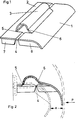
- Fig. 1 shows a molded part which consists essentially of the immovable part 2 to be connected to the object to be protected and of the movable part 1; both parts are connected by the film hinge 4 and rotatable about this until the ribs 7 and 8 stop. Both parts are also connected to the tubular segment 3 via the film hinges 5 and 6.
- part 1 pivots about the axis of rotation 4 under load P; this also pivots the hinge axis 6 and deforms the tube segment 3, which is connected to the part 2 via the hinge axis 5 and the hinge axis 6 to the part 1, in the elastic region of the plastic material.
- the joints 4 and 5 do not change their position, while the joint 6 rotates by 4, but does not reach the dead position, so that the pivot points 5, 4 and 6 do not form a straight line in the end position.
- the deformation work initiated via part 1 is limited to the stroke X by the support of the ribs 7 and 8. When part 1 is relieved, the tension in part 3 restores the initial position.
- the figure shows a molded part with only one joint, i.e. Deformation unit shown, of course, the arrangement of several joint units is possible and often useful.
- the vertical distance between the articulated line 6 and the articulated line 4 should preferably be at least three times the vertical distance between the articulated line 4 and the articulated line 5 in order to achieve sufficient deformation stress and restoring properties in the pipe segment 3.
- the length distances of the joint lines should also behave, i.e. the length distance of the joint line 5 to the joint line 4 should be at least 3 times the length distance of the joint line 4 to the joint line 6.
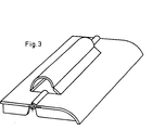
- Fig. 3 shows the construction of Fig. 1 with the difference that the joint 4 is not designed as a film hinge, but as a hinge joint.
- Fig. 4 shows a molded part which consists of a frame which e.g. has three saddle roof-like designs, each containing a triple film hinge system.
- the longer leg plate is designed so that it is inevitably deformed when it is pivoted away.
- the e.g. Deformation path limited by ribs prevents reaching the extended position of the system.
- Fig. 5 in which, in contrast to Fig. 4, the shorter leg is equipped with a vertical stabilizing rib.
- the position of the outer joint lines remains unchanged under load, i.e. only the middle line changes its position.
- Such a deformation unit is particularly suitable as a substructure.
- FIGS. 6 and 7 show a section of an analog molded part like FIGS. 4 and 5, but with the difference that an element of the film hinge system is designed as a hinge joint that can be disengaged. This makes it possible to disengage a few hinge units within a construction unit and thus change the size of the load absorption.
- FIGS. 8 and 9 An energy-absorbing molded plastic part in the unloaded state can be seen from FIGS. 8 and 9. It consists of a frame with a gable roof-like structure, each consisting of a three-film hinge system. All hinge lines change their position under load; 10 shows, here, at least in the middle Be rich, the frame partitions deformed to mutual concern. This avoids reaching the extended position of all three hinge lines.
- This construction is an example in the event that it is not a leg of the toggle lever system that is deformed, but the integrated molded part construction.
- FIG. 11 and 12 show an example of a self-supporting plastic seat shell, in which the substructure of the seat part is provided with gable roof-like designs similar to FIG. 5, each of which forms a three-part film hinge system.
- the substructure is covered by the actual seat plate. If the seat plate is loaded, it changes in height by the height jump H and in the horizontal by the dimension L. Here, an axial movement occurs against the backrest side, i.e. the seated person is pressed against the backrest.
- This construction accordingly shows the connection of the middle joint with another molded part, which takes over the movement of the middle joint under load.
Landscapes
- Engineering & Computer Science (AREA)
- General Engineering & Computer Science (AREA)
- Mechanical Engineering (AREA)
- Refuge Islands, Traffic Blockers, Or Guard Fence (AREA)
- Vibration Dampers (AREA)
- Moulds For Moulding Plastics Or The Like (AREA)
Description
- In verschiedenen Bereichen der Technik, besonders in der Fahrzeugtechnik und im Transportwesen, setzt man zum Abfangen von Bewegungsenergien, von Stössen, Schwingungen und dergleichen Elemente und Konstruktionseinheiten ein, welche imstande sind, die entsprechende Energieeinwirkung aufzufangen.
- Konstruktionen über Federelemente bis hin zu Karosserierahmenkonstruktionen zur Aufnahme einer Auffahrenergie sind bekannt. Es fehlt aber noch immer an einfachen Formteilen, die in der Massenfertigung herstellbar sind, die geringere bis mittlere dynamische Belastung, Aufschlagsenergie, Stösse oder Schwingungen aufnehmen und die entweder als Kunststoffelement an vorhandene Formteile aus Kunststoff oder anderen Werkstoffen aufmontiert werden können oder als Formteil selbst die erforderlichen Konstruktionsmerkmale tragen.
- Diese Aufgabe wird in der aus den Patenansprüchen ersichtlichen Weise elegant gelöst. Erfindungsgemäss entspricht die Verformungsarbeit, d.h. zum Beispiel die Schädigungsarbeit bei einer Stossbelastung, dem Verformungswiderstand der Elemente, wobei der Weg der Schädigungsverformung gleich dem Weg der Lageveränderung der Gelenklinien ist, wobei ein Teil der Formteilbestandteile eine elastische Formveränderung erfährt.
- Man erreicht dieses Ziel durch ein ggf. wiederkehrendes Kniehebelsystem, dessen Beweglichkeit durch mehrere Gelenke erreicht wird. In jedem System sind drei Gelenke erforderlich. Als Gelenk gilt grundsätzlich das an sich bekannte Filmscharnier. Dieses kann auch ganz oder teilweise durch ein Scharniergelenk ersetzt sein, welches, wenn es durch Aufsprengen lösbar ist, den Vorteil bietet, gewünschtenfalls auskuppelbar zu sein, so dass man einzelne von mehreren wiederkehrenden Kniehebeleinheiten ausser Betrieb nehmen und derart das Gesamtsystem auf die weiche Aufnahme geringerer Belastungen einstellen kann.
- Die Kunststoff-Formteile, die derart wenigstens drei Gelenklinien enthalten, lassen sich im Kunststoff-Spritzguss herstellen, wobei ein mit Filmscharniergelenken ausgestattetes Teil in einem Stück gefertigt wird. Bevorzugt fertigt man die Formteile z.B. durch Anbringung von Rippen so, dass die drei Gelenklinien unter Belastung nicht in die gestreckte Totpunktlage oder gar darüber hinaus geraten können.
- AusderFR-A-1 561 375 ist ein aus Kunststoff gefertigtes Kniehebelsystem bekannt, das bei Druckeinwirkung aus einer stabilen Totlage in eine zweite übergeht, wobei die Filmscharniere vorübergehend elastisch komprimiert werden, während die bewegten Formteile starr bleiben. Die Beendigung der Druckeinwirkung führt nicht zur Rückstellung des Systems, und daher ist diese Konstruktion nicht zur wiederholten Aufnahme von Stossenergie imstande.
- Fig. 1 zeigt ein Formteil, das im wesentlichen aus dem unbeweglichen, mit dem zu schützenden Gegenstand zu verbindenden Teil 2 und aus dem beweglichen Teil 1 besteht; beide Teile sind durch das Filmscharnier 4 miteinander verbunden und um dieses bis zum Anschlag der Rippen 7 und 8 drehbar. Beide Teile sind ausserdem über die Filmscharniere 5 und 6 mit dem Rohrsegment 3 verbunden.
- Wie Fig. 2 erkennen lässt, schwenkt Teil 1 bei Belastung P um die Drehachse 4; damit wird auch die Gelenkachse 6 geschwenkt und das Rohrsegment 3, welches über die Gelenkachse 5 mit dem Teil 2 und Gelenkachse 6 mit dem Teil 1 verbunden ist, im elastischen Bereich des Kunststoffmaterials verformt. Die Gelenke 4 und 5 verändern hierbei nicht die Lage, während das Gelenk 6 sich um 4 dreht, jedoch nicht die Totlage erreicht, so dass die Drehpunkte 5, 4 und 6 in der Endlage keine gestreckte Linie bilden. Die über Teil 1 eingeleitete Verformungsarbeit wird durch die Auflage der Rippen 7 und 8 auf den Hubweg X begrenzt. Bei der Entlastung des Teiles 1 bewirkt der Spannungszustand im Teil 3 die Rückstellung in die Ausgangslage.
- In der Abbildung ist ein Formteil mit nur einer Gelenk-, d.h. Verformungseinheit dargestellt, wobei selbstverständlich die Anordnung mehrerer Gelenkeinheiten möglich und vielfach zweckmässig ist.
- Bei dieser Ausführungsform soll bevorzugt der Höhenabstand der Gelenklinie 6 zu der Gelenklinie 4 mindestens das 3fache des Höhenabstandes der Gelenklinie 4 zur Gelenklinie 5 betragen, um eine ausreichende Verformungsspannung sowie Rückstelleigenschaften im Rohrsegment 3 zu erzielen. Ebenso sollen sich die Längenabstände der Gelenklinien verhalten, d.h. der Längenabstand der Gelenklinie 5 zur Gelenklinie 4 soll mindestens des 3fache des Längenabstandes der Gelenklinie 4 zur Gelenklinie 6 betragen.
- Fig. 3 zeigt die Konstruktion der Fig. 1 mit dem Unterschied, dass das Gelenk 4 nicht als Filmscharnier, sondern als Scharniergelenk ausgebildet ist.
- Fig. 4 zeigt ein Formteil, welches aus einem Rahmen besteht, der z.B. drei satteldachartige Ausbildungen besitzt, die jeweils ein dreifaches Filmscharniersystem enthalten. Die längere Schenkelplatte ist so ausgebildet, dass sie beim Abschwenken zwangsläufig deformiert wird. Der z.B. durch Rippen begrenzte Verformungsweg verhindert das Erreichen der gestreckten Lage des Systems. Dies wird aus Fig. 5 deutlich, in welcher, abweichend von Fig. 4, der kürzere Schenkel mit einer senkrechten Stabilisierungsrippe ausgestattet ist. Bei Belastung bleiben die äusseren Gelenklinien in ihrer Lage unverändert, d.h. nur die mittlere Linie verändert ihre Lage.
- Eine derartige Verformungseinheit ist vor allem als Unterkonstruktion geeignet.
- Fig. 6 und 7 zeigen als Ausschnitt ein analoges Formteil wie Fig. 4 und 5, jedoch mit dem Unterschied, dass ein Element des Filmscharniersystems als auskuppelbares Scharniergelenk ausgebildet ist. Es ist dadurch möglich, innerhalb einer Konstruktionseinheit einige Scharniereinheiten auszukuppeln und damit die Grösse der Belastungsaufnahme zu verändern.
- Aus Fig. 8 und 9 ist ein Energie aufnehmendes Kunststoff-Formteil im unbelasteten Zustand ersichtlich. Es besteht aus einem Rahmen mit satteldachartigen Ausbildungen, die je aus einem Dreier-Filmscharniersystem bestehen. Unter Belastung verändern alle Scharnierlinien ihre Lage; wie Fig. 10 erkennen lässt, werden hier, jedenfalls im mittleren Bereich, die Rahmenzwischenwände bis zum gegenseitigen Anliegen verformt. Dadurch wird das Erreichen der gestreckten Lage aller drei Scharnierlinien vermieden. Diese Konstruktion ist ein Beispiel für den Fall, dass nicht ein Schenkel des Kniehebelsystems, sondern die integrierte Formteilkonstruktion verformt wird.
- Fig. 11 und 12 zeigen als Anwendungsbeispiel eine selbsttragende Kunststoff-Sitzschale, bei der die Unterkonstruktion der Sitzflächenpartie mit satteldachartigen Ausbildungen ähnlich Fig. 5 versehen ist, die jeweils ein Dreier-Filmscharniersystem bilden. Die Unterkonstruktion ist durch die eigentliche Sitzplatte abgedeckt. Wird die Sitzplatte belastet, so verändert sie sich in der Höhe bis um den Höhensprung H und in der Waagerechten um das Mass L. Hierbei tritt eine Axialbewegung gegen die Lehnenseite ein, d.h. die sitzende Person wird an die Lehne gedrückt. Diese Konstruktion zeigt demnach die Verbindung des mittleren Gelenkes mit einem weiteren Formteil, welches bei Belastung die Bewegung des mittleren Gelenkes übernimmt.
Claims (7)
Applications Claiming Priority (2)
| Application Number | Priority Date | Filing Date | Title |
|---|---|---|---|
| DE19843429307 DE3429307A1 (de) | 1984-08-09 | 1984-08-09 | Energie aufnehmende kunststoff-formteile |
| DE3429307 | 1984-08-09 |
Publications (2)
| Publication Number | Publication Date |
|---|---|
| EP0172340A1 EP0172340A1 (de) | 1986-02-26 |
| EP0172340B1 true EP0172340B1 (de) | 1988-03-30 |
Family
ID=6242670
Family Applications (1)
| Application Number | Title | Priority Date | Filing Date |
|---|---|---|---|
| EP85107289A Expired EP0172340B1 (de) | 1984-08-09 | 1985-06-13 | Energie aufnehmende Kunststoff-Formteile |
Country Status (2)
| Country | Link |
|---|---|
| EP (1) | EP0172340B1 (de) |
| DE (2) | DE3429307A1 (de) |
Families Citing this family (3)
| Publication number | Priority date | Publication date | Assignee | Title |
|---|---|---|---|---|
| DE19825629B4 (de) * | 1998-06-08 | 2007-06-06 | Siemens Ag | Federkraftklemme |
| GB2433197B (en) * | 2005-12-15 | 2009-01-07 | R G E Engineering Company | Padded seat with resilient integral bending region |
| DE102009059246A1 (de) * | 2009-12-21 | 2011-06-22 | Beuth Hochschule für Technik Berlin, 13353 | Belastungsadaptiv ausgebildete Bauteile |
Family Cites Families (10)
| Publication number | Priority date | Publication date | Assignee | Title |
|---|---|---|---|---|
| GB622402A (en) * | 1947-03-19 | 1949-05-02 | Reginald George May | Improvements in spring devices |
| US2661942A (en) * | 1950-11-14 | 1953-12-08 | Flexible Metals Corp | Resilient cushioning device |
| FR1120259A (fr) * | 1955-01-22 | 1956-07-03 | Dispositif amortisseur à bloc élastiquement déformable | |
| DE1109463B (de) * | 1960-03-17 | 1961-06-22 | Deventer K G | Feder aus Kunststoff mit einstueckigen Anschlussteilen |
| FR1448534A (fr) * | 1965-09-29 | 1966-01-28 | Robinson Technical Products | Isolateur de chocs et de vibrations |
| FR1561375A (de) * | 1968-02-02 | 1969-03-28 | ||
| US3815887A (en) * | 1972-03-21 | 1974-06-11 | Hercules Inc | Plastic spring |
| DE2238675A1 (de) * | 1972-08-05 | 1974-02-14 | Porsche Ag | Ruhemoebel |
| IL49583A (en) * | 1976-05-14 | 1982-07-30 | Popper Eng Ltd | Compression and tension spring |
| DE2942174C2 (de) * | 1979-10-18 | 1984-04-19 | Fa. Walter Lambach, 2800 Bremen | Federkern für Matratzen, Liegen o.dgl. |
-
1984
- 1984-08-09 DE DE19843429307 patent/DE3429307A1/de not_active Withdrawn
-
1985
- 1985-06-13 EP EP85107289A patent/EP0172340B1/de not_active Expired
- 1985-06-13 DE DE8585107289T patent/DE3562041D1/de not_active Expired
Also Published As
| Publication number | Publication date |
|---|---|
| DE3429307A1 (de) | 1986-02-20 |
| EP0172340A1 (de) | 1986-02-26 |
| DE3562041D1 (en) | 1988-05-05 |
Similar Documents
| Publication | Publication Date | Title |
|---|---|---|
| EP2885554B1 (de) | Blattfederanordnung für kraftfahrzeuge | |
| DE69602976T2 (de) | Vorrichtung zum Festhalten von Gegenständen | |
| EP1785329B1 (de) | Gelenkanordnung | |
| DE4224699A1 (de) | Kunststoffgelenk zur gelenkigen Verbindung zweier Bauteile | |
| DE2707138A1 (de) | Aufhaengungsvorrichtung fuer schienenfahrzeuge | |
| DE1033052B (de) | Schwingungsdaempfer fuer Fahrzeugaufhaengungen | |
| DE2634938B2 (de) | Gelenklager-Gehäuse, insbesondere für die Schalthebel-Lagerung bei Kraftfahrzeugen | |
| DE2701984A1 (de) | Elastische anlenkung einer mittelpufferkupplung fuer schienenfahrzeuge | |
| DE3315658C2 (de) | Kugelgelenk, insbesondere Spurstangengelenk | |
| EP3597073A1 (de) | Stoss-resilient gelagerte tisch-vorrichtung | |
| DE2539698A1 (de) | Drehstabgestaenge | |
| DE102007042631A1 (de) | Schließeinheit einer Spritzgießmaschine | |
| EP0172340A1 (de) | Energie aufnehmende Kunststoff-Formteile | |
| DE2721399A1 (de) | Feder | |
| DE2756835C2 (de) | ||
| EP0271690A1 (de) | Abstützung des Kastens eines Schienenfahrzeuges auf einem Drehgestell | |
| EP0882636A3 (de) | Lenksäule mit integriertem Crashelement | |
| DE1605074B2 (de) | Drehzapfenlager, insbesondere fuer drehgestelle von schienenfahrzeugen | |
| DE202020106208U1 (de) | Modul für einen Förderer und entsprechenden Verbindungsbolzen der Bauteile eines jeden Moduls | |
| DE2612829A1 (de) | Geteilte lenksaeule | |
| DE112019003461T5 (de) | Lastbegrenzer mit einem energieabsorptionselement | |
| AT502427B1 (de) | Spritzgiessmaschine mit einem im wesentlichen c-förmigen maschinenrahmen | |
| DE112019007806T5 (de) | Fahrzeugpolsterelement | |
| AT397349B (de) | Skibremse | |
| WO1998035873A1 (de) | Gleitlager, insbesondere zur lagerung eines lukendeckels auf einem schiff |
Legal Events
| Date | Code | Title | Description |
|---|---|---|---|
| PUAI | Public reference made under article 153(3) epc to a published international application that has entered the european phase |
Free format text: ORIGINAL CODE: 0009012 |
|
| AK | Designated contracting states |
Kind code of ref document: A1 Designated state(s): CH DE FR GB IT LI NL |
|
| 17P | Request for examination filed |
Effective date: 19860301 |
|
| 17Q | First examination report despatched |
Effective date: 19870415 |
|
| GRAA | (expected) grant |
Free format text: ORIGINAL CODE: 0009210 |
|
| AK | Designated contracting states |
Kind code of ref document: B1 Designated state(s): CH DE FR GB IT LI NL |
|
| PG25 | Lapsed in a contracting state [announced via postgrant information from national office to epo] |
Ref country code: NL Effective date: 19880330 Ref country code: IT Free format text: LAPSE BECAUSE OF FAILURE TO SUBMIT A TRANSLATION OF THE DESCRIPTION OR TO PAY THE FEE WITHIN THE PRESCRIBED TIME-LIMIT;WARNING: LAPSES OF ITALIAN PATENTS WITH EFFECTIVE DATE BEFORE 2007 MAY HAVE OCCURRED AT ANY TIME BEFORE 2007. THE CORRECT EFFECTIVE DATE MAY BE DIFFERENT FROM THE ONE RECORDED. Effective date: 19880330 |
|
| GBT | Gb: translation of ep patent filed (gb section 77(6)(a)/1977) | ||
| REF | Corresponds to: |
Ref document number: 3562041 Country of ref document: DE Date of ref document: 19880505 |
|
| ET | Fr: translation filed | ||
| PG25 | Lapsed in a contracting state [announced via postgrant information from national office to epo] |
Ref country code: LI Effective date: 19880630 Ref country code: CH Effective date: 19880630 |
|
| NLV1 | Nl: lapsed or annulled due to failure to fulfill the requirements of art. 29p and 29m of the patents act | ||
| PLBE | No opposition filed within time limit |
Free format text: ORIGINAL CODE: 0009261 |
|
| STAA | Information on the status of an ep patent application or granted ep patent |
Free format text: STATUS: NO OPPOSITION FILED WITHIN TIME LIMIT |
|
| PG25 | Lapsed in a contracting state [announced via postgrant information from national office to epo] |
Ref country code: FR Free format text: LAPSE BECAUSE OF NON-PAYMENT OF DUE FEES Effective date: 19890228 |
|
| REG | Reference to a national code |
Ref country code: CH Ref legal event code: PL |
|
| PG25 | Lapsed in a contracting state [announced via postgrant information from national office to epo] |
Ref country code: DE Effective date: 19890301 |
|
| 26N | No opposition filed | ||
| REG | Reference to a national code |
Ref country code: FR Ref legal event code: ST |
|
| PG25 | Lapsed in a contracting state [announced via postgrant information from national office to epo] |
Ref country code: GB Effective date: 19890613 |
|
| GBPC | Gb: european patent ceased through non-payment of renewal fee |