EP0172268A2 - Magnetomechanische Transduktoren die Veränderungen der Resonanzfrequenz benutzen - Google Patents
Magnetomechanische Transduktoren die Veränderungen der Resonanzfrequenz benutzen Download PDFInfo
- Publication number
- EP0172268A2 EP0172268A2 EP84112621A EP84112621A EP0172268A2 EP 0172268 A2 EP0172268 A2 EP 0172268A2 EP 84112621 A EP84112621 A EP 84112621A EP 84112621 A EP84112621 A EP 84112621A EP 0172268 A2 EP0172268 A2 EP 0172268A2
- Authority
- EP
- European Patent Office
- Prior art keywords
- target
- resonant
- recited
- frequency
- strip
- Prior art date
- Legal status (The legal status is an assumption and is not a legal conclusion. Google has not performed a legal analysis and makes no representation as to the accuracy of the status listed.)
- Withdrawn
Links
- 230000005291 magnetic effect Effects 0.000 claims abstract description 48
- 230000008878 coupling Effects 0.000 claims abstract description 18
- 238000010168 coupling process Methods 0.000 claims abstract description 18
- 238000005859 coupling reaction Methods 0.000 claims abstract description 18
- 239000003302 ferromagnetic material Substances 0.000 claims abstract description 11
- 239000000463 material Substances 0.000 claims description 13
- 230000033001 locomotion Effects 0.000 claims description 10
- 239000000203 mixture Substances 0.000 claims description 9
- XEEYBQQBJWHFJM-UHFFFAOYSA-N Iron Chemical compound [Fe] XEEYBQQBJWHFJM-UHFFFAOYSA-N 0.000 claims description 5
- PXHVJJICTQNCMI-UHFFFAOYSA-N Nickel Chemical compound [Ni] PXHVJJICTQNCMI-UHFFFAOYSA-N 0.000 claims description 5
- 239000002902 ferrimagnetic material Substances 0.000 claims description 5
- 230000035945 sensitivity Effects 0.000 claims description 4
- 230000001419 dependent effect Effects 0.000 claims description 3
- 238000001514 detection method Methods 0.000 claims description 3
- 229920003023 plastic Polymers 0.000 claims description 3
- 239000004033 plastic Substances 0.000 claims description 3
- 238000001228 spectrum Methods 0.000 claims description 3
- 229910000859 α-Fe Inorganic materials 0.000 claims description 3
- ZOXJGFHDIHLPTG-UHFFFAOYSA-N Boron Chemical compound [B] ZOXJGFHDIHLPTG-UHFFFAOYSA-N 0.000 claims description 2
- OKTJSMMVPCPJKN-UHFFFAOYSA-N Carbon Chemical compound [C] OKTJSMMVPCPJKN-UHFFFAOYSA-N 0.000 claims description 2
- VYZAMTAEIAYCRO-UHFFFAOYSA-N Chromium Chemical compound [Cr] VYZAMTAEIAYCRO-UHFFFAOYSA-N 0.000 claims description 2
- ZOKXTWBITQBERF-UHFFFAOYSA-N Molybdenum Chemical compound [Mo] ZOKXTWBITQBERF-UHFFFAOYSA-N 0.000 claims description 2
- 229910052796 boron Inorganic materials 0.000 claims description 2
- 229910052799 carbon Inorganic materials 0.000 claims description 2
- 229910052804 chromium Inorganic materials 0.000 claims description 2
- 239000011651 chromium Substances 0.000 claims description 2
- 239000010941 cobalt Substances 0.000 claims description 2
- 229910017052 cobalt Inorganic materials 0.000 claims description 2
- GUTLYIVDDKVIGB-UHFFFAOYSA-N cobalt atom Chemical compound [Co] GUTLYIVDDKVIGB-UHFFFAOYSA-N 0.000 claims description 2
- BHEPBYXIRTUNPN-UHFFFAOYSA-N hydridophosphorus(.) (triplet) Chemical compound [PH] BHEPBYXIRTUNPN-UHFFFAOYSA-N 0.000 claims description 2
- 229910052742 iron Inorganic materials 0.000 claims description 2
- 229910052750 molybdenum Inorganic materials 0.000 claims description 2
- 239000011733 molybdenum Substances 0.000 claims description 2
- 229910052759 nickel Inorganic materials 0.000 claims description 2
- AJCDFVKYMIUXCR-UHFFFAOYSA-N oxobarium;oxo(oxoferriooxy)iron Chemical compound [Ba]=O.O=[Fe]O[Fe]=O.O=[Fe]O[Fe]=O.O=[Fe]O[Fe]=O.O=[Fe]O[Fe]=O.O=[Fe]O[Fe]=O.O=[Fe]O[Fe]=O AJCDFVKYMIUXCR-UHFFFAOYSA-N 0.000 claims description 2
- 229910052710 silicon Inorganic materials 0.000 claims description 2
- 239000010703 silicon Substances 0.000 claims description 2
- 241000269627 Amphiuma means Species 0.000 claims 1
- 230000001939 inductive effect Effects 0.000 claims 1
- 238000006073 displacement reaction Methods 0.000 abstract description 29
- 238000005259 measurement Methods 0.000 abstract description 8
- 229910045601 alloy Inorganic materials 0.000 description 12
- 239000000956 alloy Substances 0.000 description 12
- 230000008859 change Effects 0.000 description 8
- 239000005300 metallic glass Substances 0.000 description 7
- 239000002184 metal Substances 0.000 description 6
- 229910052751 metal Inorganic materials 0.000 description 6
- 238000000137 annealing Methods 0.000 description 5
- 230000000694 effects Effects 0.000 description 5
- 238000004146 energy storage Methods 0.000 description 5
- 230000005294 ferromagnetic effect Effects 0.000 description 5
- 229910000808 amorphous metal alloy Inorganic materials 0.000 description 4
- 230000003321 amplification Effects 0.000 description 4
- 238000005452 bending Methods 0.000 description 4
- 239000003990 capacitor Substances 0.000 description 4
- 230000002596 correlated effect Effects 0.000 description 4
- 230000005293 ferrimagnetic effect Effects 0.000 description 4
- 150000002739 metals Chemical class 0.000 description 4
- 238000000034 method Methods 0.000 description 4
- 238000003199 nucleic acid amplification method Methods 0.000 description 4
- 230000004044 response Effects 0.000 description 4
- 239000006104 solid solution Substances 0.000 description 4
- 230000004907 flux Effects 0.000 description 3
- 239000011888 foil Substances 0.000 description 3
- 230000001965 increasing effect Effects 0.000 description 3
- 238000004519 manufacturing process Methods 0.000 description 3
- 230000001960 triggered effect Effects 0.000 description 3
- 238000002441 X-ray diffraction Methods 0.000 description 2
- 230000008901 benefit Effects 0.000 description 2
- 230000015556 catabolic process Effects 0.000 description 2
- 239000002178 crystalline material Substances 0.000 description 2
- 238000006731 degradation reaction Methods 0.000 description 2
- 238000010586 diagram Methods 0.000 description 2
- 239000007788 liquid Substances 0.000 description 2
- 238000012986 modification Methods 0.000 description 2
- 230000004048 modification Effects 0.000 description 2
- 230000035699 permeability Effects 0.000 description 2
- 239000000843 powder Substances 0.000 description 2
- 238000012545 processing Methods 0.000 description 2
- 238000010791 quenching Methods 0.000 description 2
- 230000000171 quenching effect Effects 0.000 description 2
- 238000009738 saturating Methods 0.000 description 2
- 238000012546 transfer Methods 0.000 description 2
- 229910000640 Fe alloy Inorganic materials 0.000 description 1
- 239000004698 Polyethylene Substances 0.000 description 1
- 229910000676 Si alloy Inorganic materials 0.000 description 1
- NFCWKPUNMWPHLM-UHFFFAOYSA-N [Si].[B].[Fe] Chemical compound [Si].[B].[Fe] NFCWKPUNMWPHLM-UHFFFAOYSA-N 0.000 description 1
- 230000004075 alteration Effects 0.000 description 1
- 230000009286 beneficial effect Effects 0.000 description 1
- 230000005540 biological transmission Effects 0.000 description 1
- 238000009530 blood pressure measurement Methods 0.000 description 1
- 239000002131 composite material Substances 0.000 description 1
- 239000000470 constituent Substances 0.000 description 1
- 238000001816 cooling Methods 0.000 description 1
- 230000000875 corresponding effect Effects 0.000 description 1
- 238000005520 cutting process Methods 0.000 description 1
- 230000003247 decreasing effect Effects 0.000 description 1
- 230000002708 enhancing effect Effects 0.000 description 1
- 230000005669 field effect Effects 0.000 description 1
- 239000012530 fluid Substances 0.000 description 1
- 239000008187 granular material Substances 0.000 description 1
- 230000006698 induction Effects 0.000 description 1
- 238000009434 installation Methods 0.000 description 1
- 230000005381 magnetic domain Effects 0.000 description 1
- 230000007246 mechanism Effects 0.000 description 1
- 239000000155 melt Substances 0.000 description 1
- 229910001092 metal group alloy Inorganic materials 0.000 description 1
- 229920000728 polyester Polymers 0.000 description 1
- -1 polyethylene Polymers 0.000 description 1
- 229920000573 polyethylene Polymers 0.000 description 1
- 238000004804 winding Methods 0.000 description 1
Images


Classifications
-
- G—PHYSICS
- G01—MEASURING; TESTING
- G01D—MEASURING NOT SPECIALLY ADAPTED FOR A SPECIFIC VARIABLE; ARRANGEMENTS FOR MEASURING TWO OR MORE VARIABLES NOT COVERED IN A SINGLE OTHER SUBCLASS; TARIFF METERING APPARATUS; MEASURING OR TESTING NOT OTHERWISE PROVIDED FOR
- G01D5/00—Mechanical means for transferring the output of a sensing member; Means for converting the output of a sensing member to another variable where the form or nature of the sensing member does not constrain the means for converting; Transducers not specially adapted for a specific variable
- G01D5/12—Mechanical means for transferring the output of a sensing member; Means for converting the output of a sensing member to another variable where the form or nature of the sensing member does not constrain the means for converting; Transducers not specially adapted for a specific variable using electric or magnetic means
- G01D5/243—Mechanical means for transferring the output of a sensing member; Means for converting the output of a sensing member to another variable where the form or nature of the sensing member does not constrain the means for converting; Transducers not specially adapted for a specific variable using electric or magnetic means influencing the phase or frequency of AC
-
- G—PHYSICS
- G01—MEASURING; TESTING
- G01L—MEASURING FORCE, STRESS, TORQUE, WORK, MECHANICAL POWER, MECHANICAL EFFICIENCY, OR FLUID PRESSURE
- G01L9/00—Measuring steady of quasi-steady pressure of fluid or fluent solid material by electric or magnetic pressure-sensitive elements; Transmitting or indicating the displacement of mechanical pressure-sensitive elements, used to measure the steady or quasi-steady pressure of a fluid or fluent solid material, by electric or magnetic means
- G01L9/0026—Transmitting or indicating the displacement of flexible, deformable tubes by electric, electromechanical, magnetic or electromagnetic means
- G01L9/0029—Transmitting or indicating the displacement of flexible, deformable tubes by electric, electromechanical, magnetic or electromagnetic means using variations in inductance
Definitions
- This invention relates to magnetomechanical transducers, that is transducers which utilize magnetomechanical resonant frequency shifts, and more particularly to transducers capable of measuring displacements and angles, and pressure via displacements and/or rotations of pressure sensitive devices.
- Transducers of the type upon which this invention has improved are conventionally used as measurement devices to obtain an electrical signal representative of some physical quantity: for example displacement, speed, pressure and the like. Several of these transducers are presently used to measure displacement and angles.
- variable inductance transducers consist of one or two coils, a core, an armature, an exciter and an induction meter.
- a simple single coil is used as a transducer element the mechanical displacement of the armature changes the permeance of the flux path generated by the coil, thereby changing the inductance of the coil.
- the change in inductance is then measured by suitable circuitry and displayed in appropriate units.
- the main disadvantage of this transducer is mechanical loading (altered displacements and slower dynamic response) of the signal source resulting from the attachment of the armature mass to the signal source.
- Capacitive transducers provide a second method of measuring displacement. Capacitive transducers operate in two modes, changing dielectric constant or changing area. The changing area mode is used in displacement measurements. The changing area is created by shifting capacitor plates in such a way that the effective surface areas of the opposing plates are varied. This creates a change in capacitance which can be measured and correlated to desired units of displacement.
- the changing dielectric constant is most commonly used in measuring fluid levels. By replacing the vapor between the plates of a capacitor with liquid, the effective dielectric constant can be altered and thus the capacitance will vary with respect to the liquid level.
- the disadvantages of capacitance systems occur in the area of signal source loading. Capacitors require a closed active circuit to operate, thus the capacitor plate attached to the signal source must have an electrical connection to close the circuit which restricts the motion of the freely moving object in addition to increasing the objects dynamic response time.
- LVDT linear variable differential transformer
- the L VD T is a mutual inductance device using three colinear coils and a linearly movable core.
- the center coil is energized from an external ac power source and the two end coils, connected together in phase, are used as pick-up coils.
- Output amplitude and phase depend on the relative coupling of the two pick-up coils to the power coil. Relative coupling is in turn dependent on the position of the core.
- the output voltage magnitudes are ideally the same for equal core displacements on either side of null balance.
- the phase relation existing between the power source and output changes 180 degrees through null. It is therefore possible through phase determination or the use of phase sensitive circuitry to distinguish between outputs resulting from displacements on the two sides of the null.
- the LVD T offers several distinct advantages over many alternative transducers. First serving as a primary detector-transducer it converts mechanical displacement into a proportional electrical voltage which is a desirable output. The LVDT cannot be overloaded mechanically since the core is completely separable from the rest of the device. It provides a comparatively high output and is reusable, making it one of the most widely used transducers.
- the disadvantages of the LVDT are similar to those of the previously described transducers.
- One disadvantage is that intermediate amplification is required if the output signal is to be transported over a relatively short distance (e.g. more than 5 ft.).
- the LVDT is limited to relatively linear displacement measurements and short displacement detection range verses overall device length.
- the LVDT and corresponding measuring devices are expensive to manufacture, thus giving the LVDT transducer system a fairly high cost.
- dynamic measurements are hindered because the core is of appreciable mass.
- the exciting frequency of the carrier may also be a limiting factor.
- the axial force exerted by the core on the signal source is larger when the readily available 60 Hz power source is used than when power source with higher frequencies are used.
- the advantage of simple circuitry is lost if the direction from the null must be indicated.
- transducers One of the major problems with these transducers is the difficulty of obtaining an accurate measurement without altering or disturbing the system to be measured. These transducers are inefficient in that they require intermediate amplification if a remote reading is required, which results from their sensitivity to amplitude variations in their signals. Another problem with such transducers is the relatively high cost thereof.
- the present invention provides an economic, mechanical transducer system for accurately and efficiently measuring (i) displacements and angles or (ii) pressure via displacements and/or rotations of pressure sensitive devices at locations proximate or remote from the signal source (target).
- the system comprises a target adapted to be activated by an ac magnetic field and a variable dc magnetic field.
- the target comprises an elongated ductile strip of magnetostrictive ferromagnetic material enclosed for vibration within a nonmagnetic container.
- the target Upon exposure to the ac magnetic field and the variable dc magnetic field, the target produces a resonant frequency that corresponds to the effective strength of the dc bias field, and can be correlated to the angular or linear displacement of (i) an object or (ii) a pressure sensitive device associated therewith.
- the target consists of a ductile strip of magnetostrictive ferromagnetic material that is free to vibrate in a container which is surrounded by two overlapping coils.
- the coils function as an a.c. magnetic field interrogator and a receiver respectively.
- the magnetostrictive strip is excited into a mechanical resonance by the interrogating ac magnetic field, provided that the natural resonant frequency of the strip is present in the frequency band of the a.c. field.
- the variable amplitude dc magnetic field is applied, the Youngs modulus of the strip is altered ( A E effect).
- the dc magnetic field strength varies in accordance with the distance and/or orientations thereof thus, with the target held in a fixed position relative to a moving (i) object or (ii) pressure sensitive device and that object or device having applied to it a fixed dc magnetic field source, the motion of the object or device produces a variable dc magnetic field at the target.
- This variable dc magnetic field produces changes in the resonant frequencies which correspond directly to the relative positions of the object or device to the target.
- Frequency signals like digital signals have less susceptibility to outside noise sources than do analog signals.
- the present invention provides quasi-digital signal that can be transmitted over longer distances of wire with less signal amplification than that required for transmission of analog signals. Greater signal resolution is also facilitated when using frequency instead of analog signals.
- the high resolution, high signal-to-noise frequency signal of the present invention does not require the special processing equipment used for digital signals, e.g. A/D and D/A converters.
- a mechanical quantity ((i) displacement of an object or (ii) displacement and/or rotation of a pressure sensitive device) is transduced into an electrical signal by use of the AE effect on the strip.
- This electrical signal is manifested by resonant frequency shifts resulting from a change in strength of a dc magnetic field.
- a measurement of (i) physical movement or (ii) pressure via displacement and/or rotation of a pressure sensitive device can be represented directly by a frequency change that provides a signal capable of being transmitted substantial distances without the need of intermediate amplification.
- the magnetomechanical transducer system of this invention measures displacements and angles, and pressure, in an efficient, economical manner in many more measuring applications than systems wherein types of displacements are restricted to a single axis in the form of linear or rotational movement.
- the target of the magnetomechanical transducer system can be fabricated in a number of diverse sizes and configurations.
- the invention will be found to function in many varieties of measuring applications.
- the invention is described in connection with pressure measurement via displacement of a bourdon tube type pressure sensitive device.
- the invention can be employed for similar and yet diversified uses, such as angle and deflection measurements, wherein alterations in the magnetic bias field strength are correlated with the angle or deflection of an object.
- the invention is intended to encompass those modifications of the preferred embodiments wherein information concerning the position of an object is derived from variations in the dc bias field produced by a target attached thereto.
- a transducer system incorporating a target 10 composed of an amorphous magnetostrictive ribbon which is enclosed within a channel of ferrimagnetic material 12 and two co-axial coils 18 and 18'.
- the system is activated by a self-oscillating circuit 14 and the resonant frequency is displayed via a counter 16.
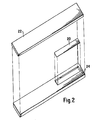
- the target 10 is comprised of an elongated ductile strip 20 of amorphous magnetostrictive ferromagnetic material enclosed within a container composed of polymeric material, such as polyethylene, consisting of two parts: a boat 24 and a cover 22.
- the container must be constructed in such a manner that the elongated ductile strip 20 remains undamped or free to vibrate upon being placed in the boat 24 and enclosed by the cover 22. This can be accomplished by leaving lmm clearance on all inside dimensions.
- the ferrimagnetic channel 12 and the coils 18 and 18' are taken to be fixed or stationary relative to a displaceable object (not shown).
- the magnetized ferrimagnetic channel 12 can be constructed from a composite of barium-ferrite powder and a plastic such as polyester. The amount of ferrite required depends on the quantity of amorphous strip enclosed. For example a 1 mil thick 1/2 inch wide ribbon typically has a ferrite/plastic weight ratio of 25% to 30%.
- the target 10 is directly linked to the displaceable object (in this case, the free end of a bourdon tube 19) and the channel is so constructed that the target slides within the channel (of ferrimagnetic material 12) in a longitudinal direction thereof, as shown by the arrow in Fig. 1, as the object (bourdon tube 15) is displaced by pressure.
- the target 10 When the target 10 is triggered, its mechanical resonant frequency serves as the reference frequency of the self-oscillating circuit 14.
- the channel of ferrimagnetic material 12 upon being magnetized provides a dc bias field whose effective strength falls off with increasing distance from the channels 12 exits 11 and 13.
- the effective bias field changes, which, in turn, creates a change in the Youngs modulus of the strip 20 due to the coupling between Young's Modulus and magnetic field strength of amorphous magnetostrictive ferromagnetic material ( A E effect).
- This in turn alters the resonant frequency of the strip 20 and thus the reference frequency of the self-oscillating circuit 14. Due to the symmetry of this transducer system, equal outputs are recorded for equivalent displacements of the strip 20 from the channel 12 exits, which doubles the transducer's range.
- fr and fa being the resonant and anti-resonant frequencies respectively (shown in Fig. 3 as fr and fa).
- fr and fa the fr of a 2 inch strip of as-cast Fe 78 Si 9 B 13 is 40 kHz
- fa is 42.7 kHz
- k 0.35.
- the self-oscillating circuit 14 may be triggered mechanically (as one would a tuning fork) or electrically, with white noise or other signals that include the natural resonant frequency of the target 10.
- the circuit shown in Figure 5 consists of a start circuit 19, an amplifier 15 and a filter 17 connected to the two coils 18 and 18' surrounding the channel 12. Once the target 10 is triggered the targets response is sent via the receiving coil to the amplifier 14. There the response is amplified and filtered to eliminate noise, then sent to the driving or interrogating coil 18.
- the resonant frequency output is substantially larger than any coexisting signal. Thus by proper choice of the selectivity of the circuit, only the resonant frequency is amplified.
- the self-oscillating circuit 14 will remain oscillating at this frequency until the resonant frequency of the target is altered. Thus the circuit 14 will track and oscillate at the same frequency as the resonant frequency of the target 10.
- the resonant frequency may be directly displayed on a simple counter 16 via the signals from either coil 18 or 18'. From the counter display the frequency can be correlated and transformed into the desired units.
- target 10 is composed of a magnetostrictive amorphous metal alloy.
- the target is in the form of an elongated, ductile strip having a first component composed of a composition consisting essentially of the formula M a N b O c X d Y e Z f , where M is at least one of iron and cobalt, N is nickel, O is at least one of chromium and molybdenum, X is at least one of boron and and phosphorous, Y is silicon, Z is carbon, "a"-"f” are in atom percent, "a” ranges from about 35-85, "b” ranges from about 0-45, “c” ranges from about 0-15 and “f” ranges from about 0-2, and the sum of d + e + f ranges from about 15-25.
- a strip of material having the formula specified above is particularly adapted to resonant mechanically at a preselected frequency of an incident magnetic field. While we do not wish to be bound by any theory, it is believed that, in targets of the aforesaid composition, direct magnetic coupling between an ac magnetic field and the target 10 occurs by means of the following mechanism.
- a ferromagnetic material such as an amorphous metal ribbon
- H magnetic field
- the ribbon's magnetic domains are caused to grow and/or rotate. This domain movement allows magnetic energy to be stored, in addition to a small amount of energy which is lost as heat.
- the domains return to their original orientation releasing the stored magnetic energy, again minus a small amount of energy lost as heat.
- Amorphous metals have high efficiency in this mode of energy storage, because they have no grain boundaries and have high resistivities.
- a magnetostrictive amorphous metal ribbon When the ferromagnetic ribbon is magnetostrictive, an additional mode of energy storage is also possible.
- This additional mode of energy storage may be viewed as an increase in the effective magnetic permeability of the ribbon.
- magnetostrictive ribbon When an ac magnetic field and a dc field are introduced on the magnetostrictive ribbon (such as can be generated by an ac and dc electric currents in a solenoid), energy is alternately stored and released with the frequency of the ac field.
- the magnetostrictive energy storage and release are maximal at the material's mechanical resonance frequency and minimal at its anti-resonance. This energy storage and release induces a voltage in a pickup coil via flux density changes in the ribbon.
- the flux density change may also be viewed as an increase in effective magnetic permeability at the resonant frequency and a decrease at anti-resonance, thus, in effect, increasing or decreasing, respectively, the magnetic coupling between the driving solenoid and a second pickup solenoid.
- the voltage induced by the purely magnetic energy exchange is linear with frequency and the change in voltage with frequency is small over a limited frequency range.
- the voltage induced by the mechanical energy exchange is also linear with frequency except near mechanical resonance.
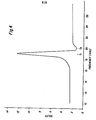
- the mechanical resonance frequency is given by: where L, E and D are the length, Young's modulus and mass density of the ribbon. Therefore, when the frequency of the ac magnetic field is swept around, fr, a characteristic signature is generated.
- the resonance peak is closely followed by an anti-resonance peak shown in Fig. 4. This anti-resonant peak occurs when the mechanical energy stored is near zero.
- MMC magnetomechanical coupling
- k (1-fr 2 /fa 2 ) 1 ⁇ 2
- fr and fa are the resonant and anti-resonant frequencies described above.
- fr and fa are the resonant and anti-resonant frequencies described above.
- fr and fa are the resonant and anti-resonant frequencies described above.
- the larger the k factor the greater the voltage difference between resonant peak and anti-resonant valley.
- the larger the k the larger the difference in frequency between resonance and anti-resonance. Therefore, a large k facilitates the observation of the MMC phenomena.
- a large k also insures a large A E effect.
- Coupling factors are influenced in a given amorphous metal by the level of bias field present, the level of internal stress (or structural anisotropy) present and by the level and direction of any magnetic anisotropy.
- Annealing an amorphous metal relieves internal stresses, thus permitting enhanced k values.
- the structural anisotropy is small due to the ribbon's amorphous nature, also enhancing k.
- Annealing in a properly oriented magnetic field can significantly enhance coupling factors. Domain movement can be maximized when the ribbon has a interrogating field. Because of demagnetizing field effects, it is practical to interrogate the ribbon only along its length (this being the longest dimension). Therefore, the induced magnetic anisotropy should be transverse to the long dimension of the ribbon.
- k Maximum values of k are obtained by annealing the ribbon in a saturating magnetic field which is perpendicular to ribbon length (cross-field annealed). For a/2 inch wide ribbon, a field of a few hundred oersteds is required.
- the annealing temperature ranges from about 300 to 450°C and the annealing time ranges from about 7 to 120 min.
- the anneal also affects the bias field required to optimize k.
- the coupling depends strongly on the bias field. At zero and saturating fields, the coupling is zero (no resonant and anti-resonant phenomena).
- an optimum bias field exists which yields a maximum k.
- the bias field required to optimize k ranges from about 0.1 to 20 Oe.
- amorphous metal yield extremely high coupling factors, and are, therefore highly preferred.
- Amorphous metals have high k because they have: (a) low magnetic losses (no grain boundaries, high resistivity), (b) low structural and stress anisotropy, (c) reasonable magnetostriction and (d) an ability to be given a beneficial magnetic anisotropy.
- Amorphous metal alloys make good targets because (a) they have high k - even as-cast, (b) they are mechanically strong, tough and ductile in bending, ( c ) they require low bias fields and (d) they have extremely high magnetostrictivity (they develop a large force upon resonating and are, therefore, more difficult to damp out). It will be appreciated, therefore, that the amorphous metals of which the target of this invention is composed need not be annealed, but may be incorporated into the target as-cast.
- Common crystalline materials such as annealed Ni have k's of 0.38 and AE's of 30%. More exotic crystalline materials, such as annealed Tb Dy Fe alloys, have k's as high as 0.55 and AE's of 150%. This last material is expensive, brittle and requires magnetic bias fields in excess of 4000 Oe.
- the amorphous ferromagnetic metal target of the invention is prepared by cooling a melt of the desired composition at a rate of at least about l0 5 °C/sec, employing metal alloy quenching techniques well-known to the amorphous metal alloy art; see, e.g., U.S. Patent 3,856,513 to Chen et al.
- the purity of all compositions is that found in normal commercial practice.
- a variety of techniques are available for fabricating continuous ribbon, wire, sheet, etc. Typically, a particular composition is selected, powders or granules of the requisite elements in the desired portions are melted and homogenized, and the molten alloy is rapidly quenched on a chill surface, such as a rapidly rotating metal cylinder.
- the metastable material may be amorphous, in which case there in no long-range order.
- X-ray diffraction patterns of amorphous alloys must be at least 50% amorphous to be sufficiently ductile to permit subsequent handling, such as stamping complex target shapes from ribbons of the alloys without degradation of the targets signal identity.
- the amorphous metal target must be at least 80% amorphous to attain superior ductility.
- the metastable phase may also be a solid solution of the constituent elements.
- such metastable, solid solution phases are not ordinarily produced under conventional processing techniques employed in the art of fabrication crystalline alloys.
- X-ray diffraction patterns of the solid solution alloys show the sharp diffraction peaks characteristic of crystalline alloys, with some broadening of the peaks due to desired fine-grained size of crystallites.
- Such metastable materials are also ductile in bending when produced under the conditions described above.
- the magnetostrictive strip 20 of which target 10 is comprised is advantageously produced in foil (or ribbon) form, and may be used in transducer applications as cast, whether the material is amorphous or a solid solution.
- foils of amorphous metal alloys may be heat treated to obtain a crystalline phase, preferably fine-grained, in order to promote longer die life when stamping of complex target shapes is contemplated.
- the amorphous ferromagnetic material of strip 20 is exceedingly ductile in bending.
- ductile is meant that the strip 20 can be bent around a radius as small as ten times the foil thickness without fracture.
- Such bending of the strip 20 produces little or no degradation in magnetic properties generated by the target upon application of the interrogating magnetic field thereto.
- the target retains its sensitivity despite being flexed or bent during (1) manufacture (e.g., cutting, stamping or otherwise forming the strip 20 into the desired length and configuration), (2) installation and (3) operation.
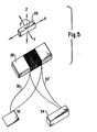
- FIG. 5 of the drawings there is shown an alternate transducer system incorporating a target 28 wrapped by two coils 30 and 30' within the effective bias field of a moveable ferromagnetic bar 26.
- the system is activated by a white noise generating circuit 32 ( Figure 7) with the resonant frequency being displayed via a counter 34.
- the self-oscillating circuit of Figure 7 can alternately be used in place of the white noise circuit.
- the target 28 in Figure 5 is similar to the target 10 of Figure 1 with the exception that the extension on the container is not required in this system.
- a detailed drawing of target 28 is shown in Figure 8.
- target 28 includes a boat 40, cover 42 and elongated, ductile strip 44.
- the ferromagnetic bar 26 may be mounted on a support (such as the free end of a bourdon tube or the needle on an analog gauge) for movement relative to said target 28 in one or more of the indicated directions to thereby produce a change in the effective bias field experienced by the target 28.
- a support such as the free end of a bourdon tube or the needle on an analog gauge
- any size or shape of ferrimagnetic or ferromagnetic materials may be applied as the bias field source, provided the magnet has a single pair of magnetic poles.
- the magnet may be directly attached to a movable object such as a pressure sensitive device or the object itself when physically possible could be magnetized.
- the white noise circuit 32 of Figure 7 includes a noise generator 31, a band pass filter 33 and an amplifier 35.
- Circuit 32 provides a continuous interrogation signal covering a close banded uniform spectrum of frequencies including the resonant frequency of the target 28.
- the output, from target 28, via the receiving coil 30 reveals the same spectrum of white noise with the exception of the resonant frequency of the target 28.
- a sharp signal appears which is markedly greater in amplitude than the noise signal.
- it is a simple matter to adjust the sensitivity of a simple counter 34 in order to display the resonant frequency.
- the two signals, the input (noise) and the output (noise plus resonant frequency) may be subtracted from each other producing a remainder of just the resonant frequency.
Landscapes
- Physics & Mathematics (AREA)
- General Physics & Mathematics (AREA)
- Electromagnetism (AREA)
- Measuring Fluid Pressure (AREA)
- Investigating Or Analyzing Materials By The Use Of Magnetic Means (AREA)
Applications Claiming Priority (4)
| Application Number | Priority Date | Filing Date | Title |
|---|---|---|---|
| US548815 | 1983-11-04 | ||
| US06/548,815 US4710709A (en) | 1983-11-04 | 1983-11-04 | Magnetomechanical transducers utilizing resonant frequency shifts to measure displacement of an object |
| US06/558,084 US4720676A (en) | 1983-11-04 | 1983-12-05 | Magnetomechanical transducer utilizing resonant frequency shifts to measure pressure in response to displacement of a pressure sensitive device |
| US558084 | 1983-12-05 |
Publications (2)
| Publication Number | Publication Date |
|---|---|
| EP0172268A2 true EP0172268A2 (de) | 1986-02-26 |
| EP0172268A3 EP0172268A3 (de) | 1987-09-02 |
Family
ID=27068947
Family Applications (1)
| Application Number | Title | Priority Date | Filing Date |
|---|---|---|---|
| EP84112621A Withdrawn EP0172268A3 (de) | 1983-11-04 | 1984-10-19 | Magnetomechanische Transduktoren die Veränderungen der Resonanzfrequenz benutzen |
Country Status (2)
| Country | Link |
|---|---|
| US (1) | US4720676A (de) |
| EP (1) | EP0172268A3 (de) |
Cited By (2)
| Publication number | Priority date | Publication date | Assignee | Title |
|---|---|---|---|---|
| CZ306170B6 (cs) * | 2006-11-30 | 2016-09-07 | Vysoká Škola Báňská - Technická Universita Ostrava | Způsob a zařízení pro zjišťování magnetických vlastností materiálu, zejména oceli |
| US12007291B2 (en) | 2018-06-20 | 2024-06-11 | Koninklijke Philips N.V. | Pressure sensing unit, system and method for remote pressure sensing |
Families Citing this family (8)
| Publication number | Priority date | Publication date | Assignee | Title |
|---|---|---|---|---|
| US5115664A (en) * | 1990-06-25 | 1992-05-26 | Ibm Corporation | Tunable feedback transducer for transient friction measurement |
| US5854589A (en) * | 1996-10-23 | 1998-12-29 | How; Hoton | Method and apparatus for generating and detecting acoustic signals |
| GB2383846A (en) * | 2002-01-02 | 2003-07-09 | Sentec Ltd | Passive biological sensor |
| US7591187B2 (en) * | 2005-05-10 | 2009-09-22 | Microstrain, Inc. | Wireless vibrating strain gauge for smart civil structures |
| JP4189426B2 (ja) * | 2007-01-31 | 2008-12-03 | 株式会社東芝 | センサ装置、及びこれを用いた携帯通信端末及び電子機器 |
| KR101012767B1 (ko) * | 2008-05-06 | 2011-02-08 | 한국표준과학연구원 | 자기변형 진동자를 이용한 용기부 내의 압력측정장치 |
| KR101068350B1 (ko) * | 2009-07-03 | 2011-09-28 | (주)디지털초음파 | 접촉 sh-도파 자왜변환기 |
| US10209322B2 (en) * | 2015-05-18 | 2019-02-19 | Peking University | Method for testing local magnetomechanical coupling coefficient of a magnetic material |
Family Cites Families (1)
| Publication number | Priority date | Publication date | Assignee | Title |
|---|---|---|---|---|
| US3706026A (en) * | 1970-11-16 | 1972-12-12 | United States Steel Corp | Apparatus for determining resonant frequencies of a specimen of magnetostrictive material |
-
1983
- 1983-12-05 US US06/558,084 patent/US4720676A/en not_active Expired - Fee Related
-
1984
- 1984-10-19 EP EP84112621A patent/EP0172268A3/de not_active Withdrawn
Non-Patent Citations (3)
| Title |
|---|
| IEEE TRANSACTIONS ON MAGNETICS, vol. MAG-12, no. 6, November 1976, pages 936-938, New York, US; K.I. ARAI et al.: "Giant delta E effect and magnetomechanical coupling factor in amorphous Fe80P13C7 ribbons * |
| IEEE TRANSACTIONS ON MAGNETICS, vol. MAG-16, no. 2, March 1980, pages 435-439, IEEE, New York, US; KENJI NARITA et al.: "Measurement of saturation magnetostriction of a thin amorphous ribbon by means of small-angle magnetization rotation" * |
| REVUE DE PHYSIQUE APPLIQUEE, vol. 18, no. 11, November 1983, pages 727-730, Orsay, FR; E. DU TREMOLET DE LACHEISSERIE et al.: "An improved capacitance method of measuring thermal expansion and magnetostriction of amorphous ribbons: application to FeNiCr metallic glasses" * |
Cited By (2)
| Publication number | Priority date | Publication date | Assignee | Title |
|---|---|---|---|---|
| CZ306170B6 (cs) * | 2006-11-30 | 2016-09-07 | Vysoká Škola Báňská - Technická Universita Ostrava | Způsob a zařízení pro zjišťování magnetických vlastností materiálu, zejména oceli |
| US12007291B2 (en) | 2018-06-20 | 2024-06-11 | Koninklijke Philips N.V. | Pressure sensing unit, system and method for remote pressure sensing |
Also Published As
| Publication number | Publication date |
|---|---|
| US4720676A (en) | 1988-01-19 |
| EP0172268A3 (de) | 1987-09-02 |
Similar Documents
| Publication | Publication Date | Title |
|---|---|---|
| US4510490A (en) | Coded surveillance system having magnetomechanical marker | |
| EP0096182B1 (de) | Verschlüsseltes Überwachungssystem mit magnetomechanischem Markierungselement | |
| US5146790A (en) | Torque sensor | |
| JP3955624B2 (ja) | 機械的共振マーカー監視システム用金属ガラス合金 | |
| EP0093281B1 (de) | Überwachungssystem mit magnetomechanischem Markierungselement | |
| EP0136086B1 (de) | Nichtkontaktierender Drehmomentfühler | |
| Egami et al. | Amorphous alloys as soft magnetic materials | |
| US5142227A (en) | Method and apparatus for measuring strain within a ferromagnetic material by sensing change in coercive field | |
| US4720676A (en) | Magnetomechanical transducer utilizing resonant frequency shifts to measure pressure in response to displacement of a pressure sensitive device | |
| EP0435885B1 (de) | Glasartige metallegierung für mechanisch resonierende sicherungsmarkierungssysteme | |
| US4931729A (en) | Method and apparatus for measuring strain or fatigue | |
| JP4447055B2 (ja) | 機械的共振型標識監視システム用金属ガラス合金 | |
| JP3955623B2 (ja) | 機械的に共振するマーカーによる監視装置用の金属ガラス合金 | |
| US7261005B2 (en) | Magneto-elastic resonator torque sensor | |
| US7561043B2 (en) | Marker for mechanically resonant article surveillance system | |
| KR20140048191A (ko) | 자기 기계 센서 요소 및 이의 전자 물품 감시 및 검출 시스템에서의 응용 | |
| US4710709A (en) | Magnetomechanical transducers utilizing resonant frequency shifts to measure displacement of an object | |
| US6432226B2 (en) | Magnetic glassy alloys for high frequency applications | |
| KR100576075B1 (ko) | 기계적 공진마커 감시시스템을 위한 금속유리합금 | |
| EP0084138B1 (de) | Metallegierungen mit Glasstruktur, einer Magnetostriktion in der Nähe von Null und hoher thermischer und magnetischer Stabilität | |
| US5495231A (en) | Metallic glass alloys for mechanically resonant marker surveillance systems | |
| US6475303B1 (en) | Magnetic glassy alloys for electronic article surveillance | |
| CN102007391B (zh) | 温度传感器及相关的远程温度感测方法 | |
| Choudhary et al. | A novel accelerometer design using the inverse magnetostrictive effect | |
| Seekircher et al. | Robust magnetoelastic force sensor using amorphous metal alloys with low magnetic interference |
Legal Events
| Date | Code | Title | Description |
|---|---|---|---|
| PUAI | Public reference made under article 153(3) epc to a published international application that has entered the european phase |
Free format text: ORIGINAL CODE: 0009012 |
|
| AK | Designated contracting states |
Designated state(s): DE FR GB |
|
| PUAL | Search report despatched |
Free format text: ORIGINAL CODE: 0009013 |
|
| RAP1 | Party data changed (applicant data changed or rights of an application transferred) |
Owner name: IDENTITECH CORPORATION |
|
| AK | Designated contracting states |
Kind code of ref document: A3 Designated state(s): DE FR GB |
|
| 17P | Request for examination filed |
Effective date: 19871009 |
|
| 17Q | First examination report despatched |
Effective date: 19890119 |
|
| STAA | Information on the status of an ep patent application or granted ep patent |
Free format text: STATUS: THE APPLICATION IS DEEMED TO BE WITHDRAWN |
|
| 18D | Application deemed to be withdrawn |
Effective date: 19890530 |
|
| RIN1 | Information on inventor provided before grant (corrected) |
Inventor name: URBANSKI, JEFFREY CARMAN Inventor name: ANDERSON III, PHILIP MARRON |