EP0171202A2 - Thermischer Bildaufnehmer - Google Patents
Thermischer Bildaufnehmer Download PDFInfo
- Publication number
- EP0171202A2 EP0171202A2 EP85304927A EP85304927A EP0171202A2 EP 0171202 A2 EP0171202 A2 EP 0171202A2 EP 85304927 A EP85304927 A EP 85304927A EP 85304927 A EP85304927 A EP 85304927A EP 0171202 A2 EP0171202 A2 EP 0171202A2
- Authority
- EP
- European Patent Office
- Prior art keywords
- frame
- liquid crystal
- thermal imager
- frames
- thermal
- Prior art date
- Legal status (The legal status is an assumption and is not a legal conclusion. Google has not performed a legal analysis and makes no representation as to the accuracy of the status listed.)
- Withdrawn
Links
Images

Classifications
-
- H—ELECTRICITY
- H04—ELECTRIC COMMUNICATION TECHNIQUE
- H04N—PICTORIAL COMMUNICATION, e.g. TELEVISION
- H04N23/00—Cameras or camera modules comprising electronic image sensors; Control thereof
- H04N23/20—Cameras or camera modules comprising electronic image sensors; Control thereof for generating image signals from infrared radiation only
- H04N23/23—Cameras or camera modules comprising electronic image sensors; Control thereof for generating image signals from infrared radiation only from thermal infrared radiation
Definitions
- This invention relates to thermal imaging systems.
- a video signal representative of a thermal image can be generated by scanning the thermal image across a single detector. Such an approach is however going to be very slow having regard to the response time of a typical detector.
- An alternative approach is to form the thermal image upon a two dimensional array of detectors. A direct connection may be made from each member of that array to the corresponding member of an array of pixels of a display device. Alternatively the outputs are read serially to form a video signal.
- Some detector signals, such as pyroelectric detectors need to be operated in chopped mode, while in the case of other detectors the use of a chopped mode is not essential but improves sensitivity.
- the output takes the form of a video signal where alternate frames of the signal are produced when the detector system is exposed to the thermal image, while the intervening frames, which are of inverted form, are produced by relaxation effects when the thermal image is prevented by the chopper from reaching the detector system.
- a video signal of this form can be applied to a CRT display system after first inverting alternate frames.
- frame-to-frame subtraction normally requires the use of a store for the storage of each successive frame in order to be able to compare it point-by-point with its . immediate successor.
- This invention is concerned with a display system for the thermal imager which will effectively perform frame-to-frame subtraction at the display itself, and thereby avoid having recourse to this storage requirement.
- a thermal imager adapted to operate in chopped mode so as to produce a video signal output in which alternate frames are inverted with respect to the intervening frames, characterised in that the video output is applied to a matrix addressed liquid crystal display device capable of grey scale representation, which display device is adapted to perform frame-to-frame subtraction by virtue of its square law response to drive voltage across its pixels.
- thermal radiation from a scene is imaged by a far infra-red (typically about 10 microns) imaging optics 1 upon an absorbing layer 2 in contact with one surface of a liquid crystal layer 3 contained within a liquid crystal cell 4.
- the cell is contained within a thermostatically controlled chamber 5 and its construction is such as to minimise thermal spreading effects in the thermal image and also thermal mass.
- the temperature of the chamber 5 is maintained at a suitable value so that the pattern of small temperature variations appearing over the area of the liquid crystal layer 3 that are created by the differential heating of the thermal image produces changes in alignment of the liquid crystal molecules. Since these molecules are optically anisotropic the thermal image has resulted in the production of a corresponding optical phase image in the liquid crystal layer.
- This phase image is in its turn used to generate an intensity contrast image at a conventional two-dimensional video image transducer 6 such as a CCD camera or Vidicon.
- the liquid crystal layer 3 is illuminated with a near infra-red (typically with a wavelength of about 1 micron) source 7 such as an injection laser via a diffusing lens 8, a linear polariser 9 and a germanium mirror 10.
- the near infra-red light transmitted through the liquid crystal layer then passes through a linear polarisation analyser 11, and imaging optics 12 which forms an image of the layer 3 upon the transducer 6.
- a chopper 13 periodically interrupts the far infra-red in synchronisation with the frame scan of the transducer 6.
- alternate frames of the video output relate to when the liquid crystal layer is being heated by the far infra-red, while the intervening frames relate to when the layer is cooling by virtue of the fact that the far infra-red is obstructed by the chopper. Therefore, the video signal is not in a suitable form for direct application to a conventional CRT type VDU, but would first need processing in some form of frame store subtractor circuit. In this instance however, the signal output from the transducer 6 is instead fed direct to a liquid crystal type VDU 14.
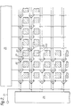
- the VDU 14 is an active silicon matrix addressed device whose basic organisation is depicted in Figure 2.
- the pixels of the VDU 14 are arranged in rows and columns, and each pixel is defined by the area of overlap between a rear electrode 20 behind the liquid crystal layer and the transparent front sheet electrode (not shown) in front of that layer.
- Each rear electrode is connected with a video signal input line 21, which is common to all rear electrodes, via an associated pair of gates 22 and 23 associated with that particular rear electrode.
- Gate 22 has to do with the row number of that electrode while gate 23 has to do with its column number. Operation of the gates is effected by control circuits 24 and 25.
- Control circuit 24 has one output line 26 associated with each row of pixel rear electrodes 20, and the gate electrodes of all their associated gates 22 are connected to this output line.
- control circuit 25 has one output line 27 associated each column of pixel rear electrodes, and the gate electrodes of their associated gates 23 are connected to this output line.
- control circuits 24 and 25 the appropriate parts of the video signal on line 21 are distributed to the appropriate pixel rear electrodes.
- the transparent front sheet electrode is maintained at a constant potential approximately midway between the levels of corresponding points of consecutive video frames. In this way the liquid crystal layer of the VDU is not exposed to any long term d.c. bias which could be responsible for engendering electrolytic degradation, and frame-to-frame subtraction is automatically effected without recourse to special frame storage measures.
Landscapes
- Health & Medical Sciences (AREA)
- Toxicology (AREA)
- Engineering & Computer Science (AREA)
- Multimedia (AREA)
- Signal Processing (AREA)
- Liquid Crystal (AREA)
- Liquid Crystal Display Device Control (AREA)
- Control Of Indicators Other Than Cathode Ray Tubes (AREA)
- Transforming Electric Information Into Light Information (AREA)
- Radiation Pyrometers (AREA)
Applications Claiming Priority (2)
| Application Number | Priority Date | Filing Date | Title |
|---|---|---|---|
| GB08419776A GB2162715A (en) | 1984-08-02 | 1984-08-02 | Thermal imaging system |
| GB8419776 | 1984-08-02 |
Publications (2)
| Publication Number | Publication Date |
|---|---|
| EP0171202A2 true EP0171202A2 (de) | 1986-02-12 |
| EP0171202A3 EP0171202A3 (de) | 1986-12-30 |
Family
ID=10564874
Family Applications (1)
| Application Number | Title | Priority Date | Filing Date |
|---|---|---|---|
| EP85304927A Withdrawn EP0171202A3 (de) | 1984-08-02 | 1985-07-10 | Thermischer Bildaufnehmer |
Country Status (3)
| Country | Link |
|---|---|
| EP (1) | EP0171202A3 (de) |
| JP (1) | JPS6141931A (de) |
| GB (1) | GB2162715A (de) |
Cited By (1)
| Publication number | Priority date | Publication date | Assignee | Title |
|---|---|---|---|---|
| WO1988010044A1 (en) * | 1987-06-03 | 1988-12-15 | The General Electric Company, P.L.C. | Thermal imaging devices |
Families Citing this family (2)
| Publication number | Priority date | Publication date | Assignee | Title |
|---|---|---|---|---|
| GB8606783D0 (en) * | 1986-03-19 | 1986-04-23 | Gen Electric Co Plc | Picture synthesizers |
| CA2117476C (en) * | 1992-06-19 | 2000-02-22 | R. Andrew Wood | Infrared camera with thermoelectric temperature stabilization |
Family Cites Families (1)
| Publication number | Priority date | Publication date | Assignee | Title |
|---|---|---|---|---|
| GB2079020B (en) * | 1980-05-30 | 1983-12-21 | Hughes Microelectronics Ltd | Method of generating input signals for subtractive combination |
-
1984
- 1984-08-02 GB GB08419776A patent/GB2162715A/en not_active Withdrawn
-
1985
- 1985-07-10 EP EP85304927A patent/EP0171202A3/de not_active Withdrawn
- 1985-07-23 JP JP16277385A patent/JPS6141931A/ja active Pending
Cited By (2)
| Publication number | Priority date | Publication date | Assignee | Title |
|---|---|---|---|---|
| WO1988010044A1 (en) * | 1987-06-03 | 1988-12-15 | The General Electric Company, P.L.C. | Thermal imaging devices |
| US4949174A (en) * | 1987-06-03 | 1990-08-14 | The General Electric Company, P.L.C. | Zoom lens thermal imager incorporating a non-pixellated detector |
Also Published As
| Publication number | Publication date |
|---|---|
| JPS6141931A (ja) | 1986-02-28 |
| EP0171202A3 (de) | 1986-12-30 |
| GB2162715A (en) | 1986-02-05 |
Similar Documents
| Publication | Publication Date | Title |
|---|---|---|
| CA1235009A (en) | Thermal imager | |
| US5049740A (en) | Multiple field of view sensor | |
| US5486698A (en) | Thermal imaging system with integrated thermal chopper | |
| US5512748A (en) | Thermal imaging system with a monolithic focal plane array and method | |
| JPH04340993A (ja) | ディスプレィ構造 | |
| US5168327A (en) | Imaging device | |
| US5604346A (en) | Arrangement for recording an IR-image | |
| GB1569574A (en) | Thermal imaging systems | |
| JPH10145802A (ja) | 視野をセグメントに分割する小型デジタルカメラ | |
| US4876453A (en) | Method and apparatus for calibrating an imaging sensor | |
| US5710428A (en) | Infrared focal plane array detecting apparatus having light emitting devices and infrared camera adopting the same | |
| EP0207153B1 (de) | Mehrblickfeld-sensor | |
| US4583814A (en) | Infra-red optical systems | |
| US4670654A (en) | Thermal image sensor with means for converting a phase image into an insity modulated image | |
| US9222838B2 (en) | Detection device, sensor device, and electronic device | |
| EP0171202A2 (de) | Thermischer Bildaufnehmer | |
| US4983837A (en) | Forward looking infrared imaging system | |
| US4362938A (en) | Infrared viewing system | |
| US4160907A (en) | Thermo-optical far infrared system | |
| US4949174A (en) | Zoom lens thermal imager incorporating a non-pixellated detector | |
| JPH02206976A (ja) | 赤外線撮像装置の感度補正方法 | |
| GB1592500A (en) | Pyroelectric infrared detection system | |
| SU209802A1 (ru) | Сканирующий радиационный пирометр | |
| Backer et al. | First-order image correction using a CID array | |
| JPS60245389A (ja) | 赤外線映像装置 |
Legal Events
| Date | Code | Title | Description |
|---|---|---|---|
| PUAI | Public reference made under article 153(3) epc to a published international application that has entered the european phase |
Free format text: ORIGINAL CODE: 0009012 |
|
| AK | Designated contracting states |
Designated state(s): AT BE CH DE FR IT LI LU NL SE |
|
| PUAL | Search report despatched |
Free format text: ORIGINAL CODE: 0009013 |
|
| AK | Designated contracting states |
Kind code of ref document: A3 Designated state(s): AT BE CH DE FR IT LI LU NL SE |
|
| STAA | Information on the status of an ep patent application or granted ep patent |
Free format text: STATUS: THE APPLICATION IS DEEMED TO BE WITHDRAWN |
|
| 18D | Application deemed to be withdrawn |
Effective date: 19871130 |
|
| RIN1 | Information on inventor provided before grant (corrected) |
Inventor name: ROSS, PETER WILLIAM |