EP0170717B1 - Verdampfungsbrenner - Google Patents
Verdampfungsbrenner Download PDFInfo
- Publication number
- EP0170717B1 EP0170717B1 EP84109484A EP84109484A EP0170717B1 EP 0170717 B1 EP0170717 B1 EP 0170717B1 EP 84109484 A EP84109484 A EP 84109484A EP 84109484 A EP84109484 A EP 84109484A EP 0170717 B1 EP0170717 B1 EP 0170717B1
- Authority
- EP
- European Patent Office
- Prior art keywords
- burning
- gas generating
- unit
- generating chamber
- preheat
- Prior art date
- Legal status (The legal status is an assumption and is not a legal conclusion. Google has not performed a legal analysis and makes no representation as to the accuracy of the status listed.)
- Expired
Links
Images



Classifications
-
- F—MECHANICAL ENGINEERING; LIGHTING; HEATING; WEAPONS; BLASTING
- F23—COMBUSTION APPARATUS; COMBUSTION PROCESSES
- F23C—METHODS OR APPARATUS FOR COMBUSTION USING FLUID FUEL OR SOLID FUEL SUSPENDED IN A CARRIER GAS OR AIR
- F23C9/00—Combustion apparatus characterised by arrangements for returning combustion products or flue gases to the combustion chamber
-
- F—MECHANICAL ENGINEERING; LIGHTING; HEATING; WEAPONS; BLASTING
- F23—COMBUSTION APPARATUS; COMBUSTION PROCESSES
- F23D—BURNERS
- F23D11/00—Burners using a direct spraying action of liquid droplets or vaporised liquid into the combustion space
- F23D11/36—Details
- F23D11/44—Preheating devices; Vaporising devices
- F23D11/441—Vaporising devices incorporated with burners
- F23D11/443—Vaporising devices incorporated with burners heated by the main burner flame
Definitions
- the present invention relates to an evaporation burner of the kind referred to in the precharacterizing portion of patent claim 1.
- the present applicant has proposed an evaporation burner in the JP-A-21170/83, in which a gas generating unit through which a preheat burning flame flows and a burning unit having therein a hollow gas chamber and a number of flame injection ports in its surface are arranged adjacent to each other.
- a distal or free end of the gas generating unit is connected to the burning unit through communication windows, so that the gas generating unit and the burning unit are rapidly preheated from the inside by the flow action of the preheat burning flame generated in the gas generating unit, and at the same time, a part of the preheat burning flame injecting through the injection ports is directed to the gas generating unit to heat the gas generating unit from the outside.
- the fuel supplied into the gas generating chamber is vaporized or gasified together with the combustion air to generate a gas mixture.
- the gas mixture is directed upwardly from the injection ports of the burning unit while heating the gas generating unit around its periphery, thereby burning the gas mixture.
- the evaporation combustion is continued.
- US-A-16 09 150 discloses a control device for heating combustible mixtures. A burner is described, wherein the incoming fuel is vaporized by the heat of combustion. The preparation of the incoming fuel is controlled by the return to a mixing chamber of exhaust gases from the combustion chamber.
- GB-A-2 119 076 discloses a fuel gasification burner having an evaporation burner comprising a burning unit having a hollow gas chamber therein and burning plates on its surface, a gas generating chamber through which a preheat burning flame may flow, said gas generating chamber being located adjacent to said burning unit and substantially along the centerlines of said burning unit, and an inlet window through which the preheat burning flame within said gas generating chamber may flow into said burning unit.
- an object of the present invention is to provide an evaporation burner wherein a gas generating chamber and a burning unit are arranged adjacent to each other, and the burning unit is connected at both sides to a distal end side and a proximal end side of the gas generating unit through recirculation windows, whereby without stagnation of the preheat burning flame in the burning unit, the preheat burning flame is freely recirculated smoothly between the gas generating unit and the burning unit, increasing a volume of the combustion chamber, attaining a complete combustion of the preheat burning flame, promoting the preheat of the gas generating unit and the burning unit and attaining an automatic transition from the wet combustion state to the vaporized combustion state for a short period of time, thereby enabling to continue a stable vaporized combustion and freely adjusting the degree of closing or opening of the recirculation windows in response to the combustion state to adjust the preheat combustion flame and the vaporized combustion flame.
- an evaporation burner comprising a burning unit having a hollow gas chamber therein and burning plates on its surface, a gas generating chamber through which a preheat burning flame may flow, the gas generating chamber being located adjacent to the burning unit and substantially along the centerline of the burning unit, and an inlet window through which the preheat burning flame within the gas generating chamber may flow into the burning unit.
- Said evaporation burner being characterized by recirculation windows through which a part of the preheat burning flame entering into the burning unit may be recirculated back to the gas generating chamber, so that the burning unit and the gas generating chamber being communicated to each other.
- said recirculation windows are adjustable to vary their closing/opening degree as desired by an opening/closing damper.
- the preheat burning flame may be burnt while being recirculated from the burning unit through the recirculation windows back to the gas generating chamber. Therefore, the burning chamber area for the preheat burning flame is remarkably increased, so that the preheat burning flame is not stagnant in the burning unit.
- the preheat burning flame would be made to flow reversely to the gas generating chamber to cause an incomplete combustion, the material resulting from the incomplete combustion to plug or clog the burning plate and to adhere to the inner surfaces of the gas generating unit and the burning unit.
- the gas generating chamber and the burning unit are preheated from the insides for a short period of time.
- the outer peripheries thereof are also heated by a part of the preheat burning flame injected from the burning plates. Thereafter, the fuel fed to the gas generating chamber is rapidly vaporized or gasified.
- the generated vaporized gas is agitated and mixed with the supplied combustion air to thereby complete gas mixture while automatically attaining the transition to the vaporized combustion.
- the recirculation windows are adjusted as desired to vary their closing/opening degree by operating the opening/closing damper, so that the recirculation amounts of the preheat burning flame and the gas mixture are freely adjusted.
- a suitable and stable preheating action orvaporized combustion is always maintained.
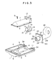
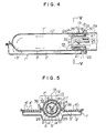
- a recessed surface 3 is integrally formed essentially along a longitudinal centerline of a flat rectangular burning unit 1.
- the recessed surface 3 is covered by an arcuate cover plate 7 so thatthe burning unit 1 is located adjacent to a gas generating chamber 10.
- the burning unit 1 is formed generally in a flat rectangular shape and has an inner hollow space which serves as a gas chamber 2.
- a number of injection ports 5 through which the gas chamber 2 communicates are formed in the surface of the burning plate 4 except for the recessed surface 3.
- a part, which is confronted with the recessed surface 3, of a bottom wall 6 of the burning unit 1 is made to project outwardly.
- the arcuate cover plate 7 is arranged so as to cover the upper portion of the recessed surface 3 of the burning unit 1.
- a peripheral edge flange 8 of the cover plate 7 is mounted on a peripheral portion of the recessed surface 3 through fastening means 9 so that the longitudinal gas generating chamber 10 having a circular cross-section is formed.
- Proximal ends of the arcuate recessed surface 3 and the arcuate cover plate 7 extends outwardly beyond the burning unit 1 by substantially the same length. This makes it possible to provide mounting flanges 11 and 12 at the proximal ends, respectively.
- the burning unit 1 and the gas generating chamber 10 which are arranged adjacent to each other as described above are connected so as to communicate with each other through a single inlet window 13 formed on the distal end side of the recessed surface 3 and two recirculation windows 14,14formed on the proximal end side in symmetrical relation with respecttothe centerline.
- a preheat burning flame generated within the gas generating chamber 10 may freely enter from the gas generating chamber 10 through the inlet window 13 to the interior of the burning unit 1. Subsequently, a part of the preheat burning flame which has entered into the gas chamber 2 may be recirculated through the two recirculation windows 14, 14 to the proximal end side of the gas generating chamber 10.
- the Preheat burning flame is freely recirculated between the burning unit 1 and the gas generating chamber 10, so that a surface area of the combustion chamber is remarkably increased and the preheating burning flame is completely burnt.
- An opening/closing damper 15 serves to fully open or close the two recirculation windows 14, 14 at the same time and to adjust the opening degree thereof as desired.
- the opening/ closing damper 15 is disposed in the gas generating chamber 10 on the proximal end side.
- the opening/closing damper 15 is composed of an elongate hollow sleeve 16 provided at its proximal end with a centrally opened bent wall 17.
- the bent wall 17 is provided with a desired number of through holes 18 equiangularly at a constant interval.
- a proximal end of a control rod 19 is fixed to the hollow sleeve 16 and the distal end thereof is assembled to project outwardly through an oblong slot 20 formed in the arcuate cover plate 7.
- Two communication openings 21, 21 which are identical with the recirculation windows 14,14 are formed at the diametrically opposite positions, in the circumferential wall of the hollow sleeve 16, to the position where the control rod 19 is mounted.
- a blower sleeve 24 Inside of the opening/closing damper 15, there is disposed a blower sleeve 24 provided integrally at a proximal end with a flange 23 which is to be mounted on the mounting flanges 11 and 12 through a packing 22.
- a main blow passage 25 is defined in the blower sleeve 24 and a sub passage 26 is defined between the opening/ closing damper 15 and the blower sleeve 24.
- the same number and configuration of through holes 27 as those of the through holes 18 are formed in the flange 23 confronted with the through holes 18.
- the through holes 27 are fully closed by the surface of the bent wall 17. Therefore, when the recirculation windows 14, 14 are opened at a desired opening degree, the through holes 27 are also opened at a corresponding opening degree so that air for combustion may flow through the sub-passage 26.
- blower 28 air for combustion is made to flow to the gas generating chamber 10 through the main blow passage 25 and the sub-passage 26.
- a flange 30 provided at a distal end of a blower sleeve 29 of the blower 28 is mounted on the flange 23 in a predetermined manner.
- An atomizing nozzle 31 is mounted substantially at the center of the main blow passage 25.
- An ignition spark plug therefor is indicated by reference numeral 32.
- an oil feed tube 33 is shown by the two dot and chain line.
- the oil feed tube 33 serves to feed the fuel to the proximal end side of the recessed surface 3 instead of the atomizing nozzle 31 and to vaporize or gasify the fuel by the preheating action.
- Spark plugs 34 for gasified combustion are arranged to face the burning plates 4, 4 at their ends.
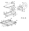
- a recessed surface 3 formed centrally essentially in the longitudinal direction of a burning unit 1' is made discrete from the burning unit 1'.
- the fuel supplied in the gas generating chamber 10' is rapidly vaporized or gasified and a stable gasified combustion may be kept for a long period of time.
- the substantially central surface of the flat rectangular burning unit 1' having therein a hollow gas chamber 2' is opened along the longitudinal direction as designated by reference numeral 35. The surface except for the opened portion is covered by burning plates 4', 4' each having a number of gas injection ports 5'.
- An upright heat transfer wall 36 is integrally provided along the three peripheral edges, i.e., right and left sides and a distal end side of the opened portion 35.
- a lower half arcuate portion of the recessed surface 3' is disposed in the burning unit 1' to some extent.
- An inlet window 13' and two recirculation windows 14', 14' are formed on the distal and proximal end sides of the recessed surface 3', respectively.
- An arcuate cover plate 7' is mounted inside of the heat transfer wall 36 provided along the three edges of the recessed surface 3'.
- The. burning plates 4', 4', the recessed surface 3' and the arcuate cover plate 7' are coupled together by fastening members 9' while the burning unit 1 / and the gas generating chamber 10' are arranged adjacent to each other and are communicable to each other through the inlet window 13' and the recirculation windows 14', 14'.
- the burning plates 4', 4' are made of ceramics in order to radiate infrared rays.
- the burning plates 4', 4' may be made of metal mesh or porous metal plates.
- the construction other than the thus far described construction is the same as that of the first embodiment.
- a preheating burning flame and gas mixture generated in the gas generating chamber 10" are injected upwardly and downwardly from the burning unit 1" to thereby further increase the burning capacity.
- the gas generating chamber 10" is in the form of a longitudinal cylinder having a closed distal end and an open proximal ends.
- a square mounting flange 37 for being mounted on a flange 23 is integrally provided at the proximal end side of the gas generating chamber 10".
- a pair of burning plates 4a" and 4b" each having a number of gas injection ports 5" in its upper and lower surfaces are provided at symmetrical positions with respect to the centerline of the elongate gas generating chamber 10".
- the same construction as in the first embodiment is adopted except for the construction where two communication ports 21 ", 21" are formed at the right and left symmetrical positions with respect to the centerline of the hollow sleeve 16" of the opening/closing damper for opening/closing the recirculation windows 14", 14" and the control rod 19" is mounted on the hollow sleeve 16" with the rod being directed downwardly.
- the flame enters into the burning unit 1 from the inlet window 13 while preheating the recessed surface 3 and the interior of the gas generating chamber, and at the same time, the flame causes a part of the preheating burning flame to be injected from the gas injection ports 5.
- the other part of the flame is introduced through the recirculation windows 14, 14 and the communication ports 21, 21 into the sub-passage 26, and then, is again recirculated into the gas generating chamber 10 together with the combustion air.
- the part of the preheating burning flame is injected from the gas injection ports 5 and the other part is freely recirculated, the area of the combustion chamber is remarkably increased and in addition, the rate of flow is also increased to thereby completely burn the fuel.
- the gas generating chamber is heated by the part of the preheat burning flame from the outside and the interior of the gas generating chamber 10 is rapidly heated to a gasifying ambient temperature.
- the fuel dispersion action of the injection nozzle 31 is temporarily interrupted, thereby stopping the continuation of the preheat burning flame and subsequently injecting and dispersing the fuel, supplied from the injection nozzle 31, into the pre-heated gas generating chamber 10 together with the combustion air.
- the fuel is rapidly vaporized or gasified by the preheating action in the flow passage.
- the generated evaporated gas is agitated and mixed with the combustion air in the flow passage, to become a complete mixture.
- the mixture is made to flow from the inlet window 13 to the burning unit 1.
- the part of the mixture is injected upwardly from the number of gas injection ports 5, and, at the same time, the other is made to recirculated the recirculation windows 14, 14, the communication ports 21, 21 and the sub-passage 26 into the gas generating chamber 10.
- the recirculation windows 14, 14 are interrupted by the circumferential wall of the hollow sleeve 16 of the opening/closing damper 15 by operating the control rod 19, thereby bringing the windows in the fully closed state.
- the mixture gas which has entered from the gas generating chamber 10 into the burning unit 1 is retained in the burning unit 1 without the recirculation, and is injected from the gas injection ports 5 under a constant pressure thereby keeping the gasified combustion stable and heating the overall gas generating chamber 10 with the part of the gasified combustion flame from the outside. Thereafter, the vaporizing gasifying action of the fuel injected into the gas generating chamber 10 is promoted.
- the through holes 27 are also under the fully closed condition and the combustion air will flow through the main blow passage 25.
- the complete combustion may readily attained, and a state in which the gas injection ports 5 would be plugged or clogged by material generated due to the incomplete combustion is prevented or an unstable condition of the evaporated gas generation due to the adhesion of the material to the gas generating chamber 10 and the inner surface of the burning unit 1 may be prevented.
- the opening degree of the recirculation windows 14, 14 is freely adjusted by the opening/closing damper 15, the recirculation amounts of the preheat combustion flame and the gas mixture may be adjusted as desired and the injection amount of the injected flame from the gas injection ports 5 may be adjusted.
- the burning unit 1 is always heated by the preheat burning flame, the gas mixture generated upon the transient vaporized combustion is prevented from being in the liquefied state.
- the heat transfer wait 36 is strongly heated by the part of the burning flame injected from a number of gas injection ports 5'.
- the overall recessed surface 3' may be preheated at the vaporized gas generating ambient temperature by the heat transfer action. Therefore, even upon the transient state from the preheat combustion to the vaporized combustion, the dispersed fuel is positively gasified or vaporized so that the gas mixture may be stably obtained and the desired vaporized combustion may be continued.
- the part of the preheat burning flame which has entered into the right and left burning units 1", 1" from the gas generating chamber 10" is simultaneously injected upwardly and downwardly through the gas injection ports 5" formed in the upper and lower surfaces of the burning plates 4a" and 4b".
- the gas generating chamber 10" is made cylindrical, not only the preheating effect is enhanced but also upon the transient state to the vaporized combustion, the great amount of the gas mixture is injected at a high speed from the upper and lower surfaces of the burning units 1", 1", thereby driving an optimum performance from the heating instrument.
Landscapes
- Engineering & Computer Science (AREA)
- Chemical & Material Sciences (AREA)
- Combustion & Propulsion (AREA)
- Mechanical Engineering (AREA)
- General Engineering & Computer Science (AREA)
- Spray-Type Burners (AREA)
- Gas Burners (AREA)
Claims (2)
- I. Verdampfungsbrenner mit einer Brennereinheit (1, 1', 1") mit einem hohlen Gasraum (2, 2', 2") und Brennerplatten (4, 4a", 4b") auf dessen Oberfläche, einer Gaserzeugungskammer (10, 10', 10"), durch die eine Vorheizungsbrennerflamme strömen kann, wobei die Gaserzeugungskammer benachbart zu der Brennereinheit und im wesentlichen entlang der Mittenlinie dieser Brennereinheit angeordnet ist und wobei ein Einlaßfenster (13, 13', 13") durch das die Vorheizbrennerflamme innerhalb der Gaserzeugungskammer in die Brennereinheit strömen kann, vorgesehen ist, gekennzeichnet durch Rückführungsfenster (14, 14', 14"), durch die ein Teil der Vorheizungsbrennerflamme, die in die Brennereinheit eintritt, in die Gaserzeugungskammer zurückgeführt wird, so daß die Brennereinheit und die Gaserzeugungskammer miteinander in Verbindung stehen.
- 2. Verdampfungsbrenner nach Anspruch I, dadurch gekennzeichnet, daß die Rückführungsfenster einstellbar sind, um deren Schließ/Offnungsgrad mittels eines Öffnungs-Schließ-Dämpfers (15, 15") einstellen zu können.
Priority Applications (2)
| Application Number | Priority Date | Filing Date | Title |
|---|---|---|---|
| DE8484109484T DE3470798D1 (en) | 1984-08-09 | 1984-08-09 | Evaporation burner |
| EP84109484A EP0170717B1 (de) | 1984-08-09 | 1984-08-09 | Verdampfungsbrenner |
Applications Claiming Priority (1)
| Application Number | Priority Date | Filing Date | Title |
|---|---|---|---|
| EP84109484A EP0170717B1 (de) | 1984-08-09 | 1984-08-09 | Verdampfungsbrenner |
Publications (2)
| Publication Number | Publication Date |
|---|---|
| EP0170717A1 EP0170717A1 (de) | 1986-02-12 |
| EP0170717B1 true EP0170717B1 (de) | 1988-04-27 |
Family
ID=8192101
Family Applications (1)
| Application Number | Title | Priority Date | Filing Date |
|---|---|---|---|
| EP84109484A Expired EP0170717B1 (de) | 1984-08-09 | 1984-08-09 | Verdampfungsbrenner |
Country Status (2)
| Country | Link |
|---|---|
| EP (1) | EP0170717B1 (de) |
| DE (1) | DE3470798D1 (de) |
Family Cites Families (6)
| Publication number | Priority date | Publication date | Assignee | Title |
|---|---|---|---|---|
| US1609150A (en) * | 1926-02-08 | 1926-11-30 | Oil Devices Corp | Control device for heating combustible mixtures |
| US1839512A (en) * | 1928-11-12 | 1932-01-05 | Russell R Waterman | Hydrocarbon burner |
| US2031306A (en) * | 1933-06-15 | 1936-02-18 | Charles A French | Liquid fuel vaporizer and burner |
| US2266046A (en) * | 1938-04-30 | 1941-12-16 | Universal Oil Burner Company I | Hydrocarbon burner |
| BE757232A (fr) * | 1969-10-08 | 1971-04-08 | Int Industries Ltd | Bruleurs |
| DE3213918C2 (de) * | 1982-04-15 | 1986-02-20 | Dowa Co., Ltd., Tokio/Tokyo | Verdampfungsbrenner für flüssige Brennstoffe |
-
1984
- 1984-08-09 DE DE8484109484T patent/DE3470798D1/de not_active Expired
- 1984-08-09 EP EP84109484A patent/EP0170717B1/de not_active Expired
Also Published As
| Publication number | Publication date |
|---|---|
| EP0170717A1 (de) | 1986-02-12 |
| DE3470798D1 (en) | 1988-06-01 |
Similar Documents
| Publication | Publication Date | Title |
|---|---|---|
| CA1297397C (en) | Burner | |
| CA2349149C (en) | Low nox apparatus and methods for burning liquid and gaseous fuels | |
| CA2119727C (en) | Method for the operation of an oil evaporation burner and an oil evaporation burner for carrying out the method | |
| CA1194776A (en) | Combustion cylinder construction for oil space heater of the type of radiating heat rays | |
| US4551089A (en) | Evaporation burner | |
| EP0170717B1 (de) | Verdampfungsbrenner | |
| CA1288039C (en) | Burner | |
| CA1224711A (en) | Evaporation burner | |
| CA1147225A (en) | Combustion device | |
| KR910000668B1 (ko) | 기화버어너 | |
| GB2096761A (en) | Blue flame oil burner | |
| KR100187026B1 (ko) | 석유연소기용 기화기 | |
| JPH0435693Y2 (de) | ||
| JPS599136Y2 (ja) | 液体燃料燃焼装置 | |
| JPH05231611A (ja) | 蒸気を形成するための発電機ボイラ内における燃焼方法、及びバーナ | |
| JPH0335944Y2 (de) | ||
| JPS6039609Y2 (ja) | 表面燃焼バ−ナ | |
| JPS6131808A (ja) | 液体燃料燃焼装置 | |
| JP3275580B2 (ja) | 燃焼式ヒータ | |
| JPH0526089B2 (de) | ||
| JPS5916650Y2 (ja) | 液体燃料給湯器 | |
| JPS605215Y2 (ja) | 液体燃料燃焼装置 | |
| JPH0249451Y2 (de) | ||
| JPS6143051Y2 (de) | ||
| WO1986003572A1 (en) | Arrangement for a burner |
Legal Events
| Date | Code | Title | Description |
|---|---|---|---|
| PUAI | Public reference made under article 153(3) epc to a published international application that has entered the european phase |
Free format text: ORIGINAL CODE: 0009012 |
|
| AK | Designated contracting states |
Designated state(s): DE FR GB IT |
|
| 17P | Request for examination filed |
Effective date: 19860214 |
|
| 17Q | First examination report despatched |
Effective date: 19861028 |
|
| GRAA | (expected) grant |
Free format text: ORIGINAL CODE: 0009210 |
|
| AK | Designated contracting states |
Kind code of ref document: B1 Designated state(s): DE FR GB IT |
|
| ITF | It: translation for a ep patent filed | ||
| REF | Corresponds to: |
Ref document number: 3470798 Country of ref document: DE Date of ref document: 19880601 |
|
| ET | Fr: translation filed | ||
| PLBE | No opposition filed within time limit |
Free format text: ORIGINAL CODE: 0009261 |
|
| STAA | Information on the status of an ep patent application or granted ep patent |
Free format text: STATUS: NO OPPOSITION FILED WITHIN TIME LIMIT |
|
| 26N | No opposition filed | ||
| PGFP | Annual fee paid to national office [announced via postgrant information from national office to epo] |
Ref country code: FR Payment date: 19920519 Year of fee payment: 9 |
|
| PGFP | Annual fee paid to national office [announced via postgrant information from national office to epo] |
Ref country code: GB Payment date: 19920806 Year of fee payment: 9 |
|
| ITTA | It: last paid annual fee | ||
| PGFP | Annual fee paid to national office [announced via postgrant information from national office to epo] |
Ref country code: DE Payment date: 19921026 Year of fee payment: 9 |
|
| PG25 | Lapsed in a contracting state [announced via postgrant information from national office to epo] |
Ref country code: GB Effective date: 19930809 |
|
| GBPC | Gb: european patent ceased through non-payment of renewal fee |
Effective date: 19930809 |
|
| PG25 | Lapsed in a contracting state [announced via postgrant information from national office to epo] |
Ref country code: FR Effective date: 19940429 |
|
| PG25 | Lapsed in a contracting state [announced via postgrant information from national office to epo] |
Ref country code: DE Effective date: 19940503 |
|
| REG | Reference to a national code |
Ref country code: FR Ref legal event code: ST |