EP0170100A2 - Gas-cooling or heating method - Google Patents
Gas-cooling or heating method Download PDFInfo
- Publication number
- EP0170100A2 EP0170100A2 EP85108326A EP85108326A EP0170100A2 EP 0170100 A2 EP0170100 A2 EP 0170100A2 EP 85108326 A EP85108326 A EP 85108326A EP 85108326 A EP85108326 A EP 85108326A EP 0170100 A2 EP0170100 A2 EP 0170100A2
- Authority
- EP
- European Patent Office
- Prior art keywords
- gas
- transfer medium
- heat transfer
- direct contact
- heat exchanger
- Prior art date
- Legal status (The legal status is an assumption and is not a legal conclusion. Google has not performed a legal analysis and makes no representation as to the accuracy of the status listed.)
- Withdrawn
Links
- 238000000034 method Methods 0.000 title claims abstract description 38
- 238000001816 cooling Methods 0.000 title claims abstract description 15
- 238000010438 heat treatment Methods 0.000 title claims abstract description 11
- 230000008569 process Effects 0.000 claims abstract description 20
- 239000007788 liquid Substances 0.000 claims abstract description 5
- 230000008859 change Effects 0.000 claims abstract description 3
- 239000007789 gas Substances 0.000 claims description 23
- XLYOFNOQVPJJNP-UHFFFAOYSA-N water Substances O XLYOFNOQVPJJNP-UHFFFAOYSA-N 0.000 claims description 17
- UGFAIRIUMAVXCW-UHFFFAOYSA-N Carbon monoxide Chemical compound [O+]#[C-] UGFAIRIUMAVXCW-UHFFFAOYSA-N 0.000 claims description 10
- 239000003546 flue gas Substances 0.000 claims description 10
- 238000009835 boiling Methods 0.000 claims description 6
- 229930195733 hydrocarbon Natural products 0.000 claims description 6
- 150000002430 hydrocarbons Chemical class 0.000 claims description 6
- 239000004215 Carbon black (E152) Substances 0.000 claims description 2
- 239000003921 oil Substances 0.000 claims description 2
- 239000002904 solvent Substances 0.000 description 7
- 239000000498 cooling water Substances 0.000 description 4
- 230000002349 favourable effect Effects 0.000 description 4
- 230000009467 reduction Effects 0.000 description 3
- 238000005406 washing Methods 0.000 description 3
- 230000008901 benefit Effects 0.000 description 2
- 230000008878 coupling Effects 0.000 description 2
- 238000010168 coupling process Methods 0.000 description 2
- 238000005859 coupling reaction Methods 0.000 description 2
- 239000013505 freshwater Substances 0.000 description 2
- 239000012535 impurity Substances 0.000 description 2
- 239000000126 substance Substances 0.000 description 2
- 230000002745 absorbent Effects 0.000 description 1
- 239000002250 absorbent Substances 0.000 description 1
- 230000003197 catalytic effect Effects 0.000 description 1
- 238000004140 cleaning Methods 0.000 description 1
- 239000000356 contaminant Substances 0.000 description 1
- 238000006477 desulfuration reaction Methods 0.000 description 1
- 230000023556 desulfurization Effects 0.000 description 1
- 239000000428 dust Substances 0.000 description 1
- 238000012856 packing Methods 0.000 description 1
- 230000008929 regeneration Effects 0.000 description 1
- 238000011069 regeneration method Methods 0.000 description 1
- 239000002918 waste heat Substances 0.000 description 1
- 239000002351 wastewater Substances 0.000 description 1
Images

Classifications
-
- B—PERFORMING OPERATIONS; TRANSPORTING
- B01—PHYSICAL OR CHEMICAL PROCESSES OR APPARATUS IN GENERAL
- B01D—SEPARATION
- B01D53/00—Separation of gases or vapours; Recovering vapours of volatile solvents from gases; Chemical or biological purification of waste gases, e.g. engine exhaust gases, smoke, fumes, flue gases, aerosols
- B01D53/34—Chemical or biological purification of waste gases
- B01D53/46—Removing components of defined structure
- B01D53/48—Sulfur compounds
- B01D53/50—Sulfur oxides
-
- F—MECHANICAL ENGINEERING; LIGHTING; HEATING; WEAPONS; BLASTING
- F23—COMBUSTION APPARATUS; COMBUSTION PROCESSES
- F23J—REMOVAL OR TREATMENT OF COMBUSTION PRODUCTS OR COMBUSTION RESIDUES; FLUES
- F23J15/00—Arrangements of devices for treating smoke or fumes
- F23J15/02—Arrangements of devices for treating smoke or fumes of purifiers, e.g. for removing noxious material
- F23J15/04—Arrangements of devices for treating smoke or fumes of purifiers, e.g. for removing noxious material using washing fluids
-
- Y—GENERAL TAGGING OF NEW TECHNOLOGICAL DEVELOPMENTS; GENERAL TAGGING OF CROSS-SECTIONAL TECHNOLOGIES SPANNING OVER SEVERAL SECTIONS OF THE IPC; TECHNICAL SUBJECTS COVERED BY FORMER USPC CROSS-REFERENCE ART COLLECTIONS [XRACs] AND DIGESTS
- Y10—TECHNICAL SUBJECTS COVERED BY FORMER USPC
- Y10S—TECHNICAL SUBJECTS COVERED BY FORMER USPC CROSS-REFERENCE ART COLLECTIONS [XRACs] AND DIGESTS
- Y10S165/00—Heat exchange
- Y10S165/909—Regeneration
Definitions
- the invention relates to a method for cooling or heating a gas before treating it in a subsequent process.
- the invention is therefore based on the object, a Ver drive to improve the type mentioned so that on the one hand allows cooling to lower temperatures and on the other hand the heating can be carried out with less effort.
- This object is achieved in that the gas is cooled or heated before the process by a first direct contact heat exchanger with a liquid heat transfer medium and that the gas after the process using the enthalpy change of the heat transfer medium by a second direct contact heat exchanger to a temperature near the starting temperature brought.
- the invention is based on the consideration that, in most cases, the gas treated in a main process must be brought back to the initial temperature after this, in order then to be released or further processed. It has now proven to be feasible and extremely expedient to couple the pre-cooling or preheating of the gas to one another before the process with this thermal aftertreatment via direct contact heat exchangers. As a result, the cold or heat content of the gas can be transferred economically to a heat transfer medium and in turn can be transferred from the latter to the treated gas before it is released.
- two variants are proposed for operating the direct contact heat exchangers.
- One possibility is that the liquid heat transfer medium itself is pumped between the first and the second direct contact heat exchanger. This procedure is particularly useful if the requirements for product purity, that is, the treated gas, allow this.
- the other variant is characterized in that by the first and by the second Direct contact heat exchanger each has its own heat transfer medium in the circuit and that the two heat transfer medium circuits are coupled to one another via an indirect heat exchanger.
- the coupling of the two heat transfer circuits by an indirect heat exchange has the great advantage over direct heat exchange that impurities which may be contained in the first heat transfer medium cannot get into the second circuit and thus into the gas to be released.
- water or a low-boiling hydrocarbon is used as the heat transfer medium. Since the gas is often loaded with water, this water can be condensed out by cooling and circulated as a first circuit. Oils which have a low vapor pressure are used in particular as hydrocarbons.
- the method according to the invention can be used in all processes which require prior cooling, for example in the case of physical washes, or heating, for example in the case of chemical washes or processes.
- the method proves to be particularly favorable in the case of physical washes, since, as is known, in these the solubility is, among other things, a function of the temperature of the laundry. In general, the solubility increases sharply with falling temperature. The necessary solution medium is inversely proportional to solubility. Since both the consumption figures and the investment costs are strongly influenced by the solvents, it is usually favorable to operate the laundry at the lowest possible temperatures.
- the method according to the invention is applied to such physical washes, a significant reduction in the amount of solvent required and, as a result, an almost proportional reduction in the size of the entire reacting part and the initial solvent filling can be achieved.
- the flue gas has the following composition:
- the flue gas is introduced into the lower part of a washing column 2.
- the gas is directly countercurrently cooled to 540 t / h water at 29 ° C from line 3 to 32 ° C and to 235 t / h water at 8 ° C from line 4 to 11 ° C.
- the cold gas is then washed in a subsequent main process step in countercurrent to cold (10 ° C.) solvent (230 t / h), which is fed via line 5 into the upper part of the washing stage.
- the solvent takes up in countercurrent S0 2 and leaves the washing stage via line 6 and, after heating in a heat exchanger 7, is passed against regenerated solvent for regeneration.
- the treated gas which is at a temperature of 10 ° C, is in a further treatment stage with second circulating water (246 t / h) from line 8, which has a temperature of 26 ° C, brought into direct heat exchange, so that it warms up and can be discharged via line 9 with compressor 10 in an amount of 250 360 m 3 / h.
- the cleaned flue gas has the following composition:
- 11,775 t / h of water at 37 ° C are drawn off from the lower part of column 2 via line 11.
- a partial flow of this water is returned to the column via line 12 in order to return contaminants, e.g. Wash out dust, HCN, HF.
- this water is drawn off together with condensate from the flue gas as a result of cooling as waste water (11.4 t / h).
- the majority of the water is circulated through a heat exchanger 14, in which it is cooled to 29 ° C by means of 26 ° C warm cooling water (1,240 t / h) and further against cold (12 ° C) second circuit water is cooled to 15 ° C.
- the cooling water heats up to 31 ° C, while the second circulating water is brought to a temperature of 26 ° C.
- the second partial stream of the first circulating water in line 4 is passed through a cooler 16 and cooled to 8 ° C. against external cold.
- the second cycle water is from the upper part of the K olonne2 withdrawn via line 17 at a temperature of 12 ° C and largely returned via the heat exchanger 14 and line 8, wherein it heats up to 26 ° C in the heat exchanger.
- a small part of the water namely 5 t / h, are added to the solvent in line 5 via line 18. Since the cleaned gas absorbs water when heated, a certain amount of fresh water must always be added. This is done via line 19, through which 11 t / h of fresh water are supplied.
Abstract
Es wird ein Verfahren zum Abkühlen oder Anwärmen eines Gases vor dessen Behandlung in einem nachfolgenden Prozeß beschrieben. Um einerseits die Abkühlung auf niedrigere Temperaturen zu ermöglichen und andererseits die Anwärmung mit geringerem Aufwand durchzuführen, wird vorgeschlagen, daß das Gas vor dem Prozeß durch einen ersten Direktkontaktwärmetauscher mit einem flüssigen Wärmeträger abgekühlt oder angewärmt wird und daß das Gas nach dem Prozeß unter Nutzung der Enthalpieänderung des Wärmeträgers durch einen zweiten Direktkontaktwärmetauscher auf eine Temperatur in der Nähe der Ausgangstemperatur gebracht wird.A method of cooling or heating a gas before treating it in a subsequent process is described. In order to enable cooling to lower temperatures on the one hand and to carry out heating with less effort on the other hand, it is proposed that the gas be cooled or heated by a first direct contact heat exchanger with a liquid heat transfer medium before the process and that the gas after the process using the enthalpy change of the heat transfer medium is brought to a temperature close to the initial temperature by a second direct contact heat exchanger.
Description
Die Erfindung betrifft ein Verfahren zum Abkühlen oder Anwärmen eines Gases vor dessen Behandlung in einem nachfolgenden Prozeß.The invention relates to a method for cooling or heating a gas before treating it in a subsequent process.
Bei vielen Prozessen in der chemischen Industrie z.B. Gasreinigungsverfahren oder katalytische Prozesse ist es nötig, das zu behandelnde Gas vor dem eigentlichen Prozeß einer Kühlung oder Anwärmung zu unterwerfen. Die Abkühlung erfolgt dabei häufig gegen Kühlwasser, da dieses am billigsten und nahezu immer vorhanden ist und gleichzeitig als Absorptionsmittel für Verunreinigungen eine Vorreinigung des Gases bewirkt. Die erreichbare Endtemperatur ist dabei allerdings durch die lokalen Kühlwasserbedingungen begrenzt. Zur Anwärmung des Gases wird oftmals Abwärme genutzt, die mittels eines Wärmeträgermediums aus dem Hauptprozeß oder einem anderen Verfahrensschritt gewonnen und an das Gas abgegeben wird. Hierzu ist jedoch meist ein großer apparativer und energieintensiver Aufwand erforderlich.In many processes in the chemical industry e.g. Gas cleaning processes or catalytic processes, it is necessary to subject the gas to be treated to cooling or heating before the actual process. The cooling often takes place against cooling water, since this is the cheapest and almost always available and at the same time, as an absorbent for impurities, causes the gas to be pre-cleaned. The final temperature that can be reached is limited by the local cooling water conditions. Waste heat is often used to heat the gas, which is obtained from the main process or another process step by means of a heat transfer medium and released to the gas. However, this usually requires a large amount of equipment and energy-intensive effort.
Der Erfindung liegt daher die Aufgabe zugrunde, ein Verfahren der eingangs genannte Art so zu verbessern, daß einerseits die Abkühlung auf niedrigere Temperaturen ermöglicht und andererseits die Anwärmung mit geringerem Aufwand durchgeführt werden kann.The invention is therefore based on the object, a Ver drive to improve the type mentioned so that on the one hand allows cooling to lower temperatures and on the other hand the heating can be carried out with less effort.
Diese Aufgabe wird erfindungsgemäß dadurch gelöst, daß das Gas vor dem Prozeß durch einen ersten Direktkontaktwärmetauscher mit einem flüssigen Wärmeträger abgekühlt oder angewärmt wird und daß das Gas nach dem Prozeß unter Nutzung der Enthalpieänderung des Wärmeträgers durch einen zweiten Direktkontaktwärmetauscher auf eine Temperatur in der Nähe der Ausgangstemperatur gebracht wird.This object is achieved in that the gas is cooled or heated before the process by a first direct contact heat exchanger with a liquid heat transfer medium and that the gas after the process using the enthalpy change of the heat transfer medium by a second direct contact heat exchanger to a temperature near the starting temperature brought.
Die Erfindung basiert auf der Überlegung, daß zumeist das in einem Hauptprozeß behandelte Gas nach diesem wieder auf die Ausgangstemperatur gebracht werden muß, um dann abgegeben oder weiterverarbeitet zurwerden. So hat es sich nun als durchführbar und äußerst zweckmäßig erwiesen, die Vorkühlung bzw. Vorwärmung des Gases vor dem Prozeß mit dieser thermischen Nachbehandlung über Direktkontaktwärmetauscher miteinander zu koppeln. Dadurch kann auf wirtschaftliche Weise der Kälte- bzw. Wärmeinhalt des Gases an ein Wärmeträgermedium abgegeben und von diesem wiederum auf das behandelte Gas vor dessen Abgabe übertragen werden.The invention is based on the consideration that, in most cases, the gas treated in a main process must be brought back to the initial temperature after this, in order then to be released or further processed. It has now proven to be feasible and extremely expedient to couple the pre-cooling or preheating of the gas to one another before the process with this thermal aftertreatment via direct contact heat exchangers. As a result, the cold or heat content of the gas can be transferred economically to a heat transfer medium and in turn can be transferred from the latter to the treated gas before it is released.
Zum Betreiben der Direktkontaktwärmetauscher werden erfindungsgemäß zwei Varianten vorgeschlagen. Die eine Möglichkeit besteht darin, daß der flüssige Wärmeträger selbst zwischen dem ersten und dem zweiten Direktkontaktwärmetauscher umgepumpt wird. Diese Verfahrensweise bietet sich insbesondere dann an, wenn die Anforderungen an die Produktreinheit, das heißt dann das behandelte Gas, dies zulassen. Die andere Variante ist dadurch gekennzeichnet, daß durch den ersten und durch den zweiten Direktkontaktwärmetauscher jeweils ein eigener Wärmeträger im Kreislauf geführt wird und daß die beiden Wärmeträgerkreisläufe über einen indirekten Wärmetauscher miteinander gekoppelt sind. Die Kopplung der beiden Wärmeträgerkreisläufe durch einen indirekten Wärmetausch hat gegenüber direktem Wärmetausch den großen Vorteil, daß eventuell im ersten Wärmeträgermedium enthaltene Verunreinigungen nicht in den zweiten Kreislauf und damit in das abzugebende Gas gelangen können.According to the invention, two variants are proposed for operating the direct contact heat exchangers. One possibility is that the liquid heat transfer medium itself is pumped between the first and the second direct contact heat exchanger. This procedure is particularly useful if the requirements for product purity, that is, the treated gas, allow this. The other variant is characterized in that by the first and by the second Direct contact heat exchanger each has its own heat transfer medium in the circuit and that the two heat transfer medium circuits are coupled to one another via an indirect heat exchanger. The coupling of the two heat transfer circuits by an indirect heat exchange has the great advantage over direct heat exchange that impurities which may be contained in the first heat transfer medium cannot get into the second circuit and thus into the gas to be released.
Mit großem Vorteil wird der direkte Wärmetausch im Gegenstrom in einer Kolonne durchgeführt. Als besonders günstig haben sich dabei Füllkörperkolonnen erwiesen. Durch geeignete Schüttungen oder Packungen wird der Wärme- bzw. Kälte- übergang bei geringem Druckverlust erheblich verbessert und .damit die=Abkühlung bzw. Anwärmung optimiert.The direct heat exchange in countercurrent is carried out with great advantage in a column. Packed columns have proven to be particularly favorable. Appropriate fillings or packings significantly improve the heat or cold transfer with little pressure loss and thus optimize cooling or heating.
In besonders vorteilhafter Ausführung des erfindungsgemäßen Verfahrens wird als Wärmeträgermedium Wasser oder ein tiefsiedender Kohlenwasserstoff verwendet. Da oftmals das Gas mit Wasser beladen ist, kann dieses Wasser durch Abkühlen auskondensiert und als erster Kreislauf zirkuliert werden. Als Kohlenwasserstoffe kommen insbesondere öle zur Anwendung, die einen niedrigen Dampfdruck aufweisen.In a particularly advantageous embodiment of the method according to the invention, water or a low-boiling hydrocarbon is used as the heat transfer medium. Since the gas is often loaded with water, this water can be condensed out by cooling and circulated as a first circuit. Oils which have a low vapor pressure are used in particular as hydrocarbons.
Das erfindungsgemäße Verfahren ist anwendbar bei allen Prozessen, die eine vorherige Abkühlung, wie z.B. bei physikalischen Wäschen, bzw. Anwärmung, wie z.B. bei chemischen Wäschen oder Prozessen, erforderlich machen. Als besonders günstig erweist sich das Verfahren jedoch bei physikalischen Wäschen, da bei diesen bekanntlich die Löslichkeit unter anderem eine Funktion der Temperatur der Wäsche ist. Im allgemeinen nimmt die Löslichkeit mit fallender Temperatur stark zu. Die notwendige Lösungsmittelmenge ist der Löslichkeit umgekehrt proportional. Da sowohl die Verbrauchszahlen als auch die Investitionskosten durch die Lösungsmittel stark beeinflußt werden, ist es meist günstig, die Wäsche bei möglichst tiefen Temperaturen zu betreiben. Bei Anwendung des erfindungsgemäßen Verfahrens auf derartige physikalische Wäschen kann somiteine deutliche Reduzierung der notwendigen Lösungsmittelmenge und dadurch bedingt eine nahezu proportionale Verkleineruna des aesamten Reaenerierteiles sowie der Lösungsmittelerstfüllung erreicht werden.The method according to the invention can be used in all processes which require prior cooling, for example in the case of physical washes, or heating, for example in the case of chemical washes or processes. However, the method proves to be particularly favorable in the case of physical washes, since, as is known, in these the solubility is, among other things, a function of the temperature of the laundry. In general, the solubility increases sharply with falling temperature. The necessary solution medium is inversely proportional to solubility. Since both the consumption figures and the investment costs are strongly influenced by the solvents, it is usually favorable to operate the laundry at the lowest possible temperatures. When the method according to the invention is applied to such physical washes, a significant reduction in the amount of solvent required and, as a result, an almost proportional reduction in the size of the entire reacting part and the initial solvent filling can be achieved.
Als aanz besonders günstig erweist sich dabei, die Anwendung des erfindunasemäßen Verfahrens auf die Rauchgasentschwefelung, die meist bei Temperaturen zwischen 20 und 60°C durchgeführt wird. Auch hier bewirkt eine weitere Absenkung der Rauchgastemperatur und damit der Wäsche eine erhöhte Wirksamkeit der Wäsche. Da das gereinigte Rauchgas zur Abgabe über Kamin wieder angewärmt werden muß, kann mit dem erfindungsgemäßen Verfahren eine günstige Kopplung zwischen Abkühlung und Anwärmung erzielt werden.The application of the process according to the invention to flue gas desulfurization, which is usually carried out at temperatures between 20 and 60 ° C., has proven particularly advantageous. Here, too, a further reduction in the flue gas temperature and thus the laundry increases the effectiveness of the laundry. Because the cleaned flue gas for delivery over Chimney must be warmed up again, a favorable coupling between cooling and heating can be achieved with the inventive method.
Im folgenden wird das erfindungsgemäße Verfahren anhand eines schematisch dargestellten Ausführungsbeispiels näher beschrieben. Bei dem gezeigten Beispiel handelt es sichThe method according to the invention is described in more detail below on the basis of a schematically illustrated exemplary embodiment. The example shown is
um eine physikalische Wäsche zur Entfernung von S02 aus Rauchgas. Es könnte jedoch auch jeder beliebige andere Prozeß zur Anwendung kommen.a physical wash to remove S0 2 from flue gas. However, any other process could also be used.
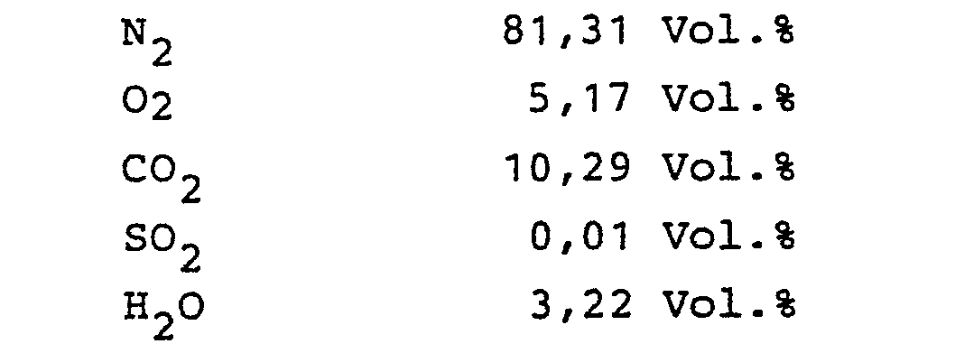
Über Leitung 1 werden 259 900 m3/h eines vorgekühlten Rauchgases mit einer Temperatur von 53°C und einem Druck von 1 bar herangeführt. Das Rauchgas hat dabei folgende Zusammensetzung:

Das Rauchgas wird in den unteren Teil einer Waschkolonne 2 eingeführt. In diesem unteren Teil wird das Gas in direktem Wärmetausch im Gegenstrom zu 540 t/h Wasser mit 29°C aus Leitung 3 auf 32°C und zu 235 t/h Wasser mit 8°C aus Leitung 4 auf 11°C gekühlt. Das kalte Gas wird sodann in einem nachfolgenden Hauptprozeßschritt im Gegenstrom zu kaltem (10°C) Lösungsmittel (230 t/h), das über Leitung 5 in den oberen Teil der Waschstufe eingespeist wird, gewaschen. Das Lösungsmittel nimmt dabei im Gegenstrom S02 auf und verläßt die Waschstufe über Leitung 6 und wird nach Anwärmung in einem Wärmetauscher 7 gegen regeneriertes Lösungsmittel zur Regenerierung geführt.The flue gas is introduced into the lower part of a washing column 2. In this lower part, the gas is directly countercurrently cooled to 540 t / h water at 29 ° C from line 3 to 32 ° C and to 235 t / h water at 8 ° C from line 4 to 11 ° C. The cold gas is then washed in a subsequent main process step in countercurrent to cold (10 ° C.) solvent (230 t / h), which is fed via
Das behandelte Gas, das mit einer Temperatur von 10°C vorliegt, wird in einer weiteren Behandlungsstufe mit zweitem Kreislaufwasser (246 t/h) aus Leitung 8, das eine Temperatur von 26°C hat, in direkte.n Wärmetausch gebracht, so daß es sich aufwärmt und über Leitung 9 mit Verdichter 10 in einer Menge von 250 360 m3/h abgegeben werden kann. Das gereinigte Rauchgas weist folgende Zusammensetzung auf:
Aus dem unteren Teil derKolonne 2 werden über Leitung 11 775 t/h Wasser mit 37°C abgezogen. Ein Teilstrom dieses Wassers wird über Leitung 12 als Rücklauf in die Säule zurückgeführt, um dort Verunreinigungen, wie z.B. Staub, HCN, HF auszuwaschen. Über Leitung 13 wird dieses Wasser zusammen mit Kondensat aus dem Rauchgas infolge Abkühlung als Abwasser (11,4 t/h) abgezogen.11,775 t / h of water at 37 ° C are drawn off from the lower part of column 2 via
Die Hauptmenge des Wassers wird jedoch im Kreislauf geführt und zwar über einen Wärmetauscher 14, in dem es zum einen mittels 26°C warmem Kühlwasser (1.240 t/h) auf 29°C abgekühlt wird und weiter gegen kaltes (12°C) zweites Kreislaufwasser auf 15°C abgekühlt wird. Das Kühlwasser erwärmt sich dabei auf 31°C, während das zweite Kreislaufwasser auf eine Temperatur von 26°C gebracht wird. Zur weiteren Abkühlung wird der zweite Teilstrom des ersten Kreislaufwassers in Leitung 4 durch einen Kühler 16 geführt und gegen Fremdkälte auf 8°C gekühlt.However, the majority of the water is circulated through a
Das zweite Kreislaufwasser wird aus dem oberen Teil der Kolonne2 über Leitung 17 mit einer Temperatur von 12°C abgezogen und zum großen Teil über den Wärmetauscher 14 und Leitung 8 zurückgeführt, wobei es sich im Wärmetauscher auf 26°C anwärmt. Ein kleiner Teil des Wassers, nämlich 5 t/h, werden über Leitung 18 dem Lösungsmittel in Leitung 5 zugemischt. Da das gereinigte Gas bei der Anwärmung Wasser aufnimmt, muß immer eine gewisse Menge Frischwasser zugeführt werden. Dies erfolgt über Leitung 19, über die 11 t/h Frischwasser zugeleitet werden.The second cycle water is from the upper part of the K olonne2 withdrawn via
Claims (9)
Applications Claiming Priority (2)
| Application Number | Priority Date | Filing Date | Title |
|---|---|---|---|
| DE3428220 | 1984-07-31 | ||
| DE19843428220 DE3428220A1 (en) | 1984-07-31 | 1984-07-31 | METHOD FOR COOLING OR WARMING A GAS |
Publications (2)
| Publication Number | Publication Date |
|---|---|
| EP0170100A2 true EP0170100A2 (en) | 1986-02-05 |
| EP0170100A3 EP0170100A3 (en) | 1988-01-27 |
Family
ID=6242027
Family Applications (1)
| Application Number | Title | Priority Date | Filing Date |
|---|---|---|---|
| EP85108326A Withdrawn EP0170100A3 (en) | 1984-07-31 | 1985-07-05 | Gas-cooling or heating method |
Country Status (6)
| Country | Link |
|---|---|
| US (1) | US4763721A (en) |
| EP (1) | EP0170100A3 (en) |
| JP (1) | JPS6193386A (en) |
| CA (1) | CA1251015A (en) |
| DD (1) | DD235563A5 (en) |
| DE (1) | DE3428220A1 (en) |
Cited By (4)
| Publication number | Priority date | Publication date | Assignee | Title |
|---|---|---|---|---|
| EP0254362A1 (en) * | 1986-07-19 | 1988-01-27 | Metallgesellschaft Ag | Process for the purification of flue gases |
| WO2013103990A3 (en) * | 2012-01-06 | 2014-01-16 | Alstom Technology Ltd | Gas treatment system with a heat exchanger for reduction of chiller energy consumption |
| US8986430B2 (en) | 2009-08-03 | 2015-03-24 | Fluor Technologies Corporation | Low-energy waste gas cooling using direct contact condenser |
| CN111939681A (en) * | 2020-08-15 | 2020-11-17 | 海南鑫鸿达建材有限公司 | Device for conveying normal-temperature liquid through pipeline and treating tail gas |
Families Citing this family (4)
| Publication number | Priority date | Publication date | Assignee | Title |
|---|---|---|---|---|
| JPH01115429A (en) * | 1987-10-30 | 1989-05-08 | Mitsubishi Heavy Ind Ltd | Supercooled mist eliminator |
| WO2009027493A1 (en) * | 2007-08-30 | 2009-03-05 | Shell Internationale Research Maatschappij B.V. | Two stage quench system for gas cooling |
| US9200805B2 (en) * | 2012-03-30 | 2015-12-01 | Alstom Technology Ltd | Condenser and method for heat recovery and cooling |
| CN104014236A (en) * | 2014-06-19 | 2014-09-03 | 南京凯盛开能环保能源有限公司 | Smoke purifying and residual heat deep recycling integrated device |
Citations (8)
| Publication number | Priority date | Publication date | Assignee | Title |
|---|---|---|---|---|
| FR619515A (en) * | 1925-07-31 | 1927-04-04 | Lindes Eismaschinen Ag | Method and apparatus for the transmission of heat between gases |
| US2838135A (en) * | 1954-01-26 | 1958-06-10 | Pilo Claes Wilhelm | Process for the recovery of heat from hot gases |
| DE1544002A1 (en) * | 1966-09-22 | 1970-06-18 | Duerrwerke Ag | Method and device for the desulphurization of hot gases |
| DE1751027A1 (en) * | 1967-03-24 | 1971-05-06 | Grenobloise Etude Appl | Heat exchanger with a liquid serving as an intermediate heat carrier |
| DE2359774A1 (en) * | 1973-11-30 | 1975-06-05 | Yasuhiro Sanga | Incinerator exhaust gas cleaning appts - with two duct portions with co- and counter-current water sprays |
| DE2505535A1 (en) * | 1975-02-10 | 1976-08-19 | Inst Gas Technology | High temp. heat exchange and sulphur cpds. removal from gas - by sprayed heavy metals or inorganic salts |
| FR2415479A1 (en) * | 1977-11-17 | 1979-08-24 | Ciba Geigy Ag | PLANT FOR CLEANING COMBUSTION GASES FROM INDUSTRIAL OVENS, IN PARTICULAR FROM HOUSEHOLD WASTE CREMATION PLANTS |
| EP0139626A2 (en) * | 1983-09-29 | 1985-05-02 | Simmering-Graz-Pauker Aktiengesellschaft | Process and apparatus for the production of heat from gases containing water vapour by absorption or adsorption |
Family Cites Families (6)
| Publication number | Priority date | Publication date | Assignee | Title |
|---|---|---|---|---|
| CA738867A (en) * | 1966-07-19 | Rostaing Michel | Heat recovery systems | |
| GB775600A (en) * | 1954-01-26 | 1957-05-29 | Claes Wilhelm Pilo | Process for the recovery of heat from hot gases |
| US3258063A (en) * | 1964-01-02 | 1966-06-28 | Monsanto Co | Heat recovery process |
| IN155791B (en) * | 1980-12-19 | 1985-03-09 | Richard John Monro | |
| DE3214958C2 (en) * | 1982-04-22 | 1986-10-30 | L. & C. Steinmüller GmbH, 5270 Gummersbach | Regenerative gas-gas heat exchanger in column design with heat transferring elements as a fluidized bed |
| GB2137523B (en) * | 1983-03-31 | 1986-06-18 | Peter Spencer | Absorbing noxious gases |
-
1984
- 1984-07-31 DE DE19843428220 patent/DE3428220A1/en not_active Withdrawn
-
1985
- 1985-07-05 EP EP85108326A patent/EP0170100A3/en not_active Withdrawn
- 1985-07-08 JP JP60148473A patent/JPS6193386A/en active Pending
- 1985-07-29 DD DD85279094A patent/DD235563A5/en unknown
- 1985-07-30 CA CA000487820A patent/CA1251015A/en not_active Expired
- 1985-07-31 US US06/760,866 patent/US4763721A/en not_active Expired - Fee Related
Patent Citations (8)
| Publication number | Priority date | Publication date | Assignee | Title |
|---|---|---|---|---|
| FR619515A (en) * | 1925-07-31 | 1927-04-04 | Lindes Eismaschinen Ag | Method and apparatus for the transmission of heat between gases |
| US2838135A (en) * | 1954-01-26 | 1958-06-10 | Pilo Claes Wilhelm | Process for the recovery of heat from hot gases |
| DE1544002A1 (en) * | 1966-09-22 | 1970-06-18 | Duerrwerke Ag | Method and device for the desulphurization of hot gases |
| DE1751027A1 (en) * | 1967-03-24 | 1971-05-06 | Grenobloise Etude Appl | Heat exchanger with a liquid serving as an intermediate heat carrier |
| DE2359774A1 (en) * | 1973-11-30 | 1975-06-05 | Yasuhiro Sanga | Incinerator exhaust gas cleaning appts - with two duct portions with co- and counter-current water sprays |
| DE2505535A1 (en) * | 1975-02-10 | 1976-08-19 | Inst Gas Technology | High temp. heat exchange and sulphur cpds. removal from gas - by sprayed heavy metals or inorganic salts |
| FR2415479A1 (en) * | 1977-11-17 | 1979-08-24 | Ciba Geigy Ag | PLANT FOR CLEANING COMBUSTION GASES FROM INDUSTRIAL OVENS, IN PARTICULAR FROM HOUSEHOLD WASTE CREMATION PLANTS |
| EP0139626A2 (en) * | 1983-09-29 | 1985-05-02 | Simmering-Graz-Pauker Aktiengesellschaft | Process and apparatus for the production of heat from gases containing water vapour by absorption or adsorption |
Non-Patent Citations (2)
| Title |
|---|
| COMBUSTION, Oktober 1970, Seiten 12-21, New York, US; C.S. DENNIS: "Potential solutions to utilities SO2 problems in the '70's" * |
| POWER, Band 127, Nr. 2, Februar 1983, Seiten 43-45, Conford, New Hampshire, US; W. ELLISON et al.: "New developments advance forced-oxidation FGD" * |
Cited By (4)
| Publication number | Priority date | Publication date | Assignee | Title |
|---|---|---|---|---|
| EP0254362A1 (en) * | 1986-07-19 | 1988-01-27 | Metallgesellschaft Ag | Process for the purification of flue gases |
| US8986430B2 (en) | 2009-08-03 | 2015-03-24 | Fluor Technologies Corporation | Low-energy waste gas cooling using direct contact condenser |
| WO2013103990A3 (en) * | 2012-01-06 | 2014-01-16 | Alstom Technology Ltd | Gas treatment system with a heat exchanger for reduction of chiller energy consumption |
| CN111939681A (en) * | 2020-08-15 | 2020-11-17 | 海南鑫鸿达建材有限公司 | Device for conveying normal-temperature liquid through pipeline and treating tail gas |
Also Published As
| Publication number | Publication date |
|---|---|
| DD235563A5 (en) | 1986-05-14 |
| DE3428220A1 (en) | 1986-02-13 |
| JPS6193386A (en) | 1986-05-12 |
| EP0170100A3 (en) | 1988-01-27 |
| US4763721A (en) | 1988-08-16 |
| CA1251015A (en) | 1989-03-14 |
Similar Documents
| Publication | Publication Date | Title |
|---|---|---|
| EP0022181B1 (en) | Process and apparatus for regenerating sulfuric acid | |
| DE19645487C1 (en) | Process and device for cleaning gases with heat exchangers | |
| EP0170100A2 (en) | Gas-cooling or heating method | |
| DE3018664A1 (en) | METHOD AND DEVICE FOR REGENERATING SULFURIC ACID | |
| DE3933731C2 (en) | ||
| DE2045984C2 (en) | Method for removing CO? 2? and / or H? 2? S from gas mixtures | |
| DE3022180A1 (en) | METHOD FOR WASHING H (DOWN ARROW) 2 (DOWN ARROW) S FROM COOKING GAS | |
| EP3212740B1 (en) | Reduction of naphthalene in coke oven gas | |
| DE3030435C2 (en) | Process for in particular multi-stage washing out of acidic constituents such as CO 2, HCN and in particular H 2 S from gases, in particular coke oven gas, by means of an ammoniacal cycle scrubbing | |
| EP0520316B1 (en) | Process for the selective removal of H2S | |
| DE1056634B (en) | Process for heat recovery from streams of gases, vapors or their mixtures with a moistening and a drying process | |
| AT401048B (en) | METHOD AND DEVICE FOR REMOVING AMMONIUM COMPOUNDS FROM WASTEWATER | |
| DE3627777A1 (en) | Process for regenerating a detergent | |
| DE2928138A1 (en) | Exhausted adsorption beds cooled and dried after regeneration - by warm exhaust gas contg. impurities and mixed with original gas | |
| DE2703474C3 (en) | Process for gas drying and SO3 absorption in the production of sulfuric acid | |
| DE3236441C2 (en) | Method for humidifying a gas stream, in particular for methanol and / or ammonia plants | |
| DE2558754B2 (en) | PROCESS FOR REMOVING HYDROGEN SULFUR FROM GASES, IN PARTICULAR COOKING GAS | |
| EP0103674B1 (en) | Process and device for carrying off free and combined ammonia from aqueous solutions containing both components | |
| EP0022473B1 (en) | Process and apparatus for regenerating sulphuric acid | |
| DE4012141A1 (en) | METHOD FOR PRE-COOKING RAW COOKING GAS AND FOR DESORPING WASHING WATER AND CONDENSATE OF COOKING | |
| EP0264580A1 (en) | Process and device for desulfurisation of flue gas | |
| DE2653869C2 (en) | Method and device for the coarse cleaning of gases | |
| CH662803A5 (en) | Process and apparatus for purifying waste water | |
| DE4116576C2 (en) | Process for extracting excess coke oven water as a reverse osmosis permeate | |
| DE845795C (en) | Process for cooling mixtures of ammonia, water vapor and carbon dioxide and / or hydrogen sulfide |
Legal Events
| Date | Code | Title | Description |
|---|---|---|---|
| PUAI | Public reference made under article 153(3) epc to a published international application that has entered the european phase |
Free format text: ORIGINAL CODE: 0009012 |
|
| AK | Designated contracting states |
Designated state(s): AT BE CH DE FR GB IT LI NL |
|
| PUAL | Search report despatched |
Free format text: ORIGINAL CODE: 0009013 |
|
| AK | Designated contracting states |
Kind code of ref document: A3 Designated state(s): AT BE CH DE FR GB IT LI NL |
|
| 17P | Request for examination filed |
Effective date: 19880414 |
|
| 17Q | First examination report despatched |
Effective date: 19880722 |
|
| STAA | Information on the status of an ep patent application or granted ep patent |
Free format text: STATUS: THE APPLICATION IS DEEMED TO BE WITHDRAWN |
|
| 18D | Application deemed to be withdrawn |
Effective date: 19900201 |
|
| RIN1 | Information on inventor provided before grant (corrected) |
Inventor name: BECKER, HANS, DR.-ING. |