EP0169363A2 - Device, in particular a travelling wiping device for automotive vehicles - Google Patents
Device, in particular a travelling wiping device for automotive vehicles Download PDFInfo
- Publication number
- EP0169363A2 EP0169363A2 EP85107386A EP85107386A EP0169363A2 EP 0169363 A2 EP0169363 A2 EP 0169363A2 EP 85107386 A EP85107386 A EP 85107386A EP 85107386 A EP85107386 A EP 85107386A EP 0169363 A2 EP0169363 A2 EP 0169363A2
- Authority
- EP
- European Patent Office
- Prior art keywords
- bearing
- piston
- carriage
- plane
- slide
- Prior art date
- Legal status (The legal status is an assumption and is not a legal conclusion. Google has not performed a legal analysis and makes no representation as to the accuracy of the status listed.)
- Granted
Links
Images


Classifications
-
- B—PERFORMING OPERATIONS; TRANSPORTING
- B60—VEHICLES IN GENERAL
- B60S—SERVICING, CLEANING, REPAIRING, SUPPORTING, LIFTING, OR MANOEUVRING OF VEHICLES, NOT OTHERWISE PROVIDED FOR
- B60S1/00—Cleaning of vehicles
- B60S1/02—Cleaning windscreens, windows or optical devices
- B60S1/04—Wipers or the like, e.g. scrapers
- B60S1/32—Wipers or the like, e.g. scrapers characterised by constructional features of wiper blade arms or blades
- B60S1/34—Wiper arms; Mountings therefor
- B60S1/36—Variable-length arms
- B60S1/365—Variable-length arms the effective length being automatically varied during angular oscillation of the arm
Definitions
- the invention relates to a device, in particular a lifting wiper system for motor vehicles, which has the features from the preamble of claim 1.
- the bearing of the piston of such a device should be accurate and durable. It may also be necessary to guide the piston so that it cannot be rotated about its longitudinal axis. For example, in a lifting wiper system in which a wiper arm is attached to the piston and is intended to move a wiper blade over a window of a motor vehicle, forces act on the piston that want to rotate it about its longitudinal direction. If the piston is moved back and forth via a crank mechanism, torsional forces may also act on it.
- a slide is attached to the end of the piston, which extends at least approximately perpendicular to the piston and is guided longitudinally on two sides of the piston on two guide elements fixed to the housing.
- Another possibility is to store the piston directly in only one bearing and to design and arrange the slide and the guide elements in such a way that the longitudinal direction of the piston is predetermined by the three bearing points and at the same time the piston is prevented from rotating.
- the object of the invention is to develop a device, in particular a lifting wiper system for motor vehicles, which has the features from the preamble of claim 1, so that a safe and largely jam-free guidance of the piston is obtained even without precise adjustment of the guide elements.
- the piston is guided closed in the bearing directly surrounding it and the slide on one guide element.
- closed guidance means that the respective guide element fixes the sliding body, that is to say the piston or the slide, in all directions lying normal to the sliding direction. Even if the piston to g e - b is a self-aligning bearing of bearings, the piston is then guided without play and accurately.
- the bearing with which the slide is moved on the one guide element is self-adjusting at least in the plane determined by the two guide elements and there is play in this plane between the slide and the second guide element, deviations in distance and in parallelism can occur of the two guide elements, especially in the plane determined by them, so that the risk of jamming and thus stiffness of the piston is very low. Torsional forces acting on the piston can of course also be dissipated via the slide via the second guide element.
- self-adjusting in one plane means that it can be pivoted about an axis that is perpendicular to the plane.
- the second guide element reaches through an elongated hole in the slide.
- the hole is completely surrounded by material, so that the stability of the slide is greater than if an opening opening outwards were used instead of the elongated hole.
- the play of the guide element in the elongated hole will be made so large that the maximum deviation occurring in the in-plane distance between the two guide elements can be compensated for.
- An embodiment is preferred in which the elongated hole is located in a second bearing introduced into the carriage.
- the second bearing is held against rotation about certain axes on the slide according to claims 5 and 6.
- the anti-rotation device can be achieved in a simple manner by training according to claims 7 to 9.
- both bearings are self-adjusting perpendicular to the plane which is determined by the two guide elements. This can compensate for any tolerances in the position of the guide elements, especially perpendicular to the plane mentioned.
- spherical bearings are used as bearings according to claims 11 and 12.
- guide elements are cylindrical columns according to claim 14, this contributes to good guidance and to simple manufacture and assembly of the individual parts.
- a housing (11) is secured against rotation on a wiper shaft (10), which is part of the wiper arm and is composed of two components, namely a base plate (12) and a cover (13).
- the base plate (12) is fastened to the wiper shaft (10).
- a piston (14) is mounted in a spherical bearing (15) inside the housing (11). This is located in the bearing holder (16), which is pressed into the bearing seat (17) of the cover (13).
- the spherical bearing (15) can be pivoted as a self-aligning bearing in two axes perpendicular to one another and in the longitudinal direction of the piston (14) in the bearing receptacle (16). It adjoins the front (19) of the housing (11) directly on the inside.
- At a distance from the spherical bearing (15) there is an inwardly projecting transverse wall (20) on the cover (13) of the housing (11), which has a bore (21) in the center through which the piston (14) freely passes.
- a coupling rod (30) is attached to the piston (14) between the transverse wall (20) and the bearing (15) via a ball pin (31), the other end of which is articulated to the free end of a crank (27). This is secured against rotation on a shaft (28) which is mounted in a sleeve (25) of the base plate (12), protrudes beyond this base plate and carries a gear (29) there against rotation.
- This gear wheel (29) is rotated during the oscillating movement of the housing (11). Its rotation is originally on the K bel of the piston (14) operating converted into a reciprocating motion.
- a carriage (35) is held against rotation with DIE s em, which unloads in two opposite sides of the piston (14).
- the slide is made of plastic and is sprayed directly onto a corrugated section (36) of the piston (14).
- Both bearings like the bearing (15), are slide bearings.
- the slide (35) is longitudinally guided on two cylindrical guide columns (39) and (40) which are arranged parallel to one another.
- the two columns (39) and (40) k through bores in the transverse wall (20) and in the end-side end wall (41) of the Gescousedek- els (13) inserted and fixed by caulking. You are therefore at the same component, namely the lid (13) of the overall h äuses (11) as the bearing (15). They extend parallel to the piston b s (14) and are with respect to this piston diametrically g nAbout e. It has been said that the two columns (39) and (40) are parallel to each other. This is fundamentally correct and desired by the construction. Due to the occurrence of tolerances, however, one must assume that the actual position of the columns (39) and (40) to one another deviates somewhat from a parallel position.
- the two bearings (37) and (38) are designed in a very special way in a lifting wiper system according to the invention.
- the bearing (38) has a bore (45), the diameter of which corresponds to the diameter of the column (40).
- the bearing (38) and the column (40) thus provide a closed guide for the slide (35), that is to say a guide which fixes the slide in all directions perpendicular to the longitudinal direction of the column (40). The distance between the piston (14) and the column (40) is thus fixed, so that the piston (14) is guided without play.
- the bearing (38) is also a spherical bearing, which is both about an axis that is perpendicular to the plane (46) defined by the two parallel columns (39) and (40), and about an axis that lies in this plane and runs perpendicular to the longitudinal direction of the column (40), pivotable.
- the bearing (37) does not have a bore with a circular cross section, but an elongated hole (47), the longitudinal extent of which lies in the plane (46). Perpendicular to this, the dimension of the elongated hole (47) corresponds to the diameter of the column (39), so that in this direction the column (39) also contributes to the guidance of the slide (35) and the piston (14). In particular, it can absorb torsional forces.
- the bearing (37) and its seat in the carriage (35) are designed so that the bearing about an axis parallel to the longitudinal direction the column (39) and thus the direction of movement of the piston (14) is secured against rotation.
- the bearing (37) is also secured against rotation about an axis perpendicular to the plane (46).
- the bearing (37) originating from a spherical bearing that was flattened on two diametrically opposite sides.
- the bearing (37) thus has two flattened, flat and parallel surfaces (48). These two surfaces are perpendicular to a straight line running in the longitudinal direction of the elongated hole (47) and thus perpendicular to the plane (46), but parallel to the guide column (39).
- the bearing (37) can therefore still be pivoted about an axis which lies in the plane (46) and is perpendicular to the column (39). It can be described as a flattened spherical bearing.
Abstract
Der Kolben einer Hub-Wischeranlage, an dem ein Wischarm befestigt ist, ist in einem Kalottenlager linear verschiebbar geführt und besitzt einen Schlitten, der beidseitig des Kolbens an zwei gehäusefesten Führungselementen längsgeführt ist. Um eine verklemmungsfreie Führung ohne Justagearbeiten an den Führungselementen zu erhalten, ist der Schlitten auf dem einen Führungselement mit einem Kalottenlager geschlossen geführt. Zwischen dem Schlitten und dem zweiten Führungselement dagegen ist in der durch die Führungselemente bestimmten Ebene ein Spiel vorhanden.The piston of a lifting wiper system, to which a wiper arm is attached, is guided in a spherical bearing in a linearly displaceable manner and has a slide which is guided longitudinally on both sides of the piston on two guide elements fixed to the housing. In order to obtain a jam-free guide without adjustment work on the guide elements, the slide is guided closed on one guide element with a spherical bearing. On the other hand, there is play between the slide and the second guide element in the plane determined by the guide elements.
Description
Die Erfindung geht aus von einer Vorrichtung, insbesondere von einer Hub-Wischeranlage für Kraftfahrzeuge, die die Merkmale aus dem Oberbegriff des Anspruchs 1 aufweist.The invention relates to a device, in particular a lifting wiper system for motor vehicles, which has the features from the preamble of claim 1.
Die Lagerung des Kolbens einer derartigen Vorrichtung soll genau und langlebig sein. Auch kann es nötig sein, den Kolben so zu führen, daß er nicht um seine Längsachse verdreht werden kann. So greifen zum Beispiel bei einer Hub-Wischeranlage, bei der am Kolben ein Wischarm befestigt ist, der ein Wischblatt über eine Scheibe eines Kraftfahrzeugs bewegen soll, Kräfte am Kolben an, die diesen um seine Längsrichtung verdrehen wollen. Wird der Kolben über einen Kurbeltrieb hin- und herbewegt, so wirken auch dadurch evtl. Torsionskräfte auf ihn ein.The bearing of the piston of such a device should be accurate and durable. It may also be necessary to guide the piston so that it cannot be rotated about its longitudinal axis. For example, in a lifting wiper system in which a wiper arm is attached to the piston and is intended to move a wiper blade over a window of a motor vehicle, forces act on the piston that want to rotate it about its longitudinal direction. If the piston is moved back and forth via a crank mechanism, torsional forces may also act on it.
Für eine gute Führung des Kolbens kann man sich verschiedene Anordnungen vorstellen. So ist es zum Beispiel möglich, den Kolben in zwei Lagern, die einen Abstand voneinander haben, zu lagern. Dazu ist am Ende des Kolbens ein Schlitten befestigt, der sich wenigstens annähernd senkrecht zum Kolben erstreckt und beidseitig des Kolbens an zwei gehäusefesten Führungselementen längsgeführt ist.Various arrangements can be imagined for good guidance of the piston. For example, it is possible to store the piston in two bearings that are spaced apart. For this purpose, a slide is attached to the end of the piston, which extends at least approximately perpendicular to the piston and is guided longitudinally on two sides of the piston on two guide elements fixed to the housing.
Während die beiden Lager die Längsrichtung des Kolbens bestimmen, wird dieser durch den Schlitten gegen Verdrehung gesichert.While the two bearings determine the longitudinal direction of the piston, it is secured against rotation by the slide.
Eine andere Möglichkeit ist, den Kolben direkt nur in einem Lager zu lagern und den Schlitten und die Führungselemente so zu gestalten und zueinander anzuordnen, daß durch die drei Lagerstellen die Längsrichtung des Kolbens vorgegeben ist und zugleich eine Verdrehsicherung des Kolbens erreicht wird.Another possibility is to store the piston directly in only one bearing and to design and arrange the slide and the guide elements in such a way that the longitudinal direction of the piston is predetermined by the three bearing points and at the same time the piston is prevented from rotating.
Aufgabe der Erfindung ist es, eine Vorrichtung, insbesondere eine Hub-Wischeranlage für Kraftfahrzeuge, die die Merkmale aus dem Oberbegriff des Anspruchs 1 aufweist, so weiterzuentwickeln, daß auch ohne eine genaue Einstellung der Führungselemente eine sichere und weitgehend verklemmungsfreie Führung des Kolbens erhalten wird.The object of the invention is to develop a device, in particular a lifting wiper system for motor vehicles, which has the features from the preamble of claim 1, so that a safe and largely jam-free guidance of the piston is obtained even without precise adjustment of the guide elements.
Diese Aufgabe wird erfindungsgemäß dadurch gelöst, daß man eine Vorrichtung, insbesondere eine Hub-Wischeranlage für Kraftfahrzeuge,mit den Merkmalen aus dem Oberbegriff des Anspruchs 1 zusätzlich mit den Merkmalen aus dem kennzeichnenden Teil dieses Anspruchs ausstattet.This object is achieved in that a device, in particular a lifting wiper system for motor vehicles, with the features from the preamble of claim 1 is additionally equipped with the features from the characterizing part of this claim.
Bei einer erfindungsgemäßen Vorrichtung sind der Kolben in dem ihn direkt umgebenden Lager und der Schlitten auf dem einen Führungselement geschlossen geführt. Geschlossen geführt heißt dabei, daß das jeweilige Führungselement den Gleitkörper, also den Kolben bzw. den Schlitten, in allen normal zur Schieberichtung liegenden Richtungen fixiert. Auch wenn das den Kolben umge- bende Lager ein selbsteinstellendes Lager ist, wird der Kolben dann spielfrei und genau geführt.In a device according to the invention, the piston is guided closed in the bearing directly surrounding it and the slide on one guide element. In this case, closed guidance means that the respective guide element fixes the sliding body, that is to say the piston or the slide, in all directions lying normal to the sliding direction. Even if the piston to g e - b is a self-aligning bearing of bearings, the piston is then guided without play and accurately.
Da außerdem das Lager, mit dem der Schlitten auf dem einen Führungselement bewegt wird, zumindest in der durch die beiden Führungselemente bestimmten Ebene selbsteinstellend und in dieser Ebene zwischen dem Schlitten und dem zweiten Führungselement ein Spiel vorhanden ist, können Abweichungen im Abstand und in der Parallelität der beiden Führungselemente vor allem in der durch sie bestimmten Ebene ausgeglichen werden, so daß die Gefahr einer Verklemmung und damit einer Schwergängigkeit des Kolbens sehr gering ist. Am Kolben angreifende Torsionskräfte können natürlich über den Schlitten auch noch über das zweite Führungselement abgeleitet werden. Selbsteinstellend in einer Ebene heißt für ein Lager, daß dieses um eine Achse, die senkrecht auf der Ebene steht, verschwenkbar ist.In addition, since the bearing with which the slide is moved on the one guide element is self-adjusting at least in the plane determined by the two guide elements and there is play in this plane between the slide and the second guide element, deviations in distance and in parallelism can occur of the two guide elements, especially in the plane determined by them, so that the risk of jamming and thus stiffness of the piston is very low. Torsional forces acting on the piston can of course also be dissipated via the slide via the second guide element. For a bearing, self-adjusting in one plane means that it can be pivoted about an axis that is perpendicular to the plane.
Vorteilhafte Ausgestaltungen der Erfindung kann man den Unteransprüchen entnehmen.Advantageous embodiments of the invention can be found in the subclaims.
So ist es vorteilhaft, wenn das zweite Führungselement durch ein Langloch des Schlittens hindurchgreift. Das Loch wird vollständig von Material umgeben, so daß die Stabilität des Schlittens größer ist, als wenn an Stelle des Langlochs eine sich nach außen öffnende Aussparung verwendet würde. Zweckmäßigerweise wird man das Spiel des Führungselements in dem Langloch gerade so groß machen, daß die maximal vorkommende Abweichung im in der Ebene liegenden Abstand der beiden Führungselemente voneinander ausgleichbar ist.It is advantageous if the second guide element reaches through an elongated hole in the slide. The hole is completely surrounded by material, so that the stability of the slide is greater than if an opening opening outwards were used instead of the elongated hole. Expediently, the play of the guide element in the elongated hole will be made so large that the maximum deviation occurring in the in-plane distance between the two guide elements can be compensated for.
Bevorzugt wird eine Ausführung, bei der sich gemäß Anspruch 4 das Langloch in einem in den Schlitten eingebrachten zweiten Lager befindet. Um zu verhindern, daß das Langloch seine Lage in ungünstiger Weise verändert, ist gemäß den Ansprüchen 5 und 6 das zweite Lager um bestimmte Achsen verdrehsicher am Schlitten gehalten.An embodiment is preferred in which the elongated hole is located in a second bearing introduced into the carriage. In order to prevent the elongated hole from changing its position in an unfavorable manner, the second bearing is held against rotation about certain axes on the slide according to claims 5 and 6.
Die Verdrehsicherung kann man auf einfache Weise durch Ausbildungen gemäß den Ansprüchen 7 bis 9 erreichen.The anti-rotation device can be achieved in a simple manner by training according to claims 7 to 9.
Es ist von Vorteil, wenn gemäß Anspruch 10 beide Lager senkrecht zur Ebene, die von den beiden Führungselementen bestimmt wird, selbsteinstellend sind. Dadurch können evtl. auftretende Toleranzen in der Lage der Führungselemente, vor allem senkrecht zu der erwähnten Ebene, ausgeglichen werden.It is advantageous if, according to
Vorteilhafterweise werden gemäß den Ansprüchen 11 und 12 als Lager Kalottenlager verwendet.Advantageously, spherical bearings are used as bearings according to
Sind gemäß Anspruch 14 die Führungselemente zylindrische Säulen, so trägt dies zu einer guten Führung und zu einer einfachen Herstellung und Montage der einzelnen Teile bei.If the guide elements are cylindrical columns according to
Vereinfacht wird die Herstellung und Montage auch, wenn der Schlitten aus Kunststoff besteht.Manufacturing and assembly are also simplified if the slide is made of plastic.
Ein erfindungsgemäßes Ausführungsbeispiel einer Hub-Wischeranlage ist in den Zeichnungen dargestellt. Anhand der Figuren dieser Zeichnungen soll die Erfindung nun näher erläutert werden.An exemplary embodiment of a lifting wiper system according to the invention is shown in the drawings. The invention will now be explained in more detail with reference to the figures of these drawings.
Es zeigen
- Fiqur 1 einen Längsschnitt durch das über eine Wischerwelle pendelnde antreibbare Gehäuse einer Hub-Wischeranlage mit einem im Gehäuse gelagerten, längsverschiebbaren Kolben,
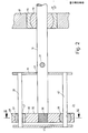
- Fig. 2 einen Schnitt entlang der Linie II-II in Fig. 1 durch die für die Führung des Kolbens wesentlichen Teile der Hub-Wischeranlage, wobei die Abstände der Teile voneinander und die Abmessungen der Teile selbst nicht mit den entsprechenden Maßen aus Fig. 1 übereinstimmen,und
- Fig. 3 einen Schnitt entlang der Linie III-III aus Fig.2.
- 1 shows a longitudinal section through the drivable housing of a reciprocating wiper system which oscillates over a wiper shaft and has a longitudinally displaceable piston which is mounted in the housing,
- 2 shows a section along the line II-II in FIG. 1 through the parts of the lifting-wiper system which are essential for guiding the piston, the spacing of the parts from one another and the dimensions of the parts themselves not having the corresponding dimensions from FIG. 1 match, and
- 3 shows a section along the line III-III from FIG.
Bei der gezeigten Hub-Wischeranlage ist auf einer Wischerwelle (10) ein Gehäuse (11) verdrehsicher befestigt, das Teil des Wischarms ist und aus zwei Bauteilen, nämlich einer Grundplatte (12) und einem Deckel (13), zusammengesetzt ist. An der Wischerwelle (10) befestigt ist die Grundplatte (12). Innerhalb des Gehäuses (11) ist ein Kolben (14) in einem Kalottenlager (15) gelagert. Dieses befindet sich in der Lageraufnahme (16), die in den Lagersitz (17) des Deckels (13) eingepresst ist. Das Kalottenlager (15) ist als sich selbst einstellendes Lager in zwei senkrecht aufeinander und auf der Längsrichtung des Kolbens (14) stehende Achsen in der Lageraufnahme (16) verschwenkbar. Es schließt sich unmittelbar innen an die Vorderseite (19) des Gehäuses (11) an. Im Abstand zum Kalottenlager (15) befindet sich am Deckel (13) des Gehäuses (11) eine nach innen ragende Querwand (20), die mittig eine Bohrung (21) aufweist, durch die der Kolben (14) frei hindurchtritt.In the lifting wiper system shown, a housing (11) is secured against rotation on a wiper shaft (10), which is part of the wiper arm and is composed of two components, namely a base plate (12) and a cover (13). The base plate (12) is fastened to the wiper shaft (10). A piston (14) is mounted in a spherical bearing (15) inside the housing (11). This is located in the bearing holder (16), which is pressed into the bearing seat (17) of the cover (13). The spherical bearing (15) can be pivoted as a self-aligning bearing in two axes perpendicular to one another and in the longitudinal direction of the piston (14) in the bearing receptacle (16). It adjoins the front (19) of the housing (11) directly on the inside. At a distance from the spherical bearing (15) there is an inwardly projecting transverse wall (20) on the cover (13) of the housing (11), which has a bore (21) in the center through which the piston (14) freely passes.
Zwischen der Querwand (20) und dem Lager (15) ist am Kolben (14) über einen Kugelbolzen (31) eine Koppelstange (30) befestigt, deren anderes Ende gelenkig mit dem freien Ende einer Kurbel (27) verbunden ist. Diese ist verdrehsicher auf einer Welle (28) befestigt, die in einer Hülse (25) der Grundplatte (12) gelagert ist, über diese Grundplatte hinaus vorsteht und dort verdrehsicher ein Zahnrad (29) trägt.A coupling rod (30) is attached to the piston (14) between the transverse wall (20) and the bearing (15) via a ball pin (31), the other end of which is articulated to the free end of a crank (27). This is secured against rotation on a shaft (28) which is mounted in a sleeve (25) of the base plate (12), protrudes beyond this base plate and carries a gear (29) there against rotation.
Dieses Zahnrad (29) wird während der pendelnden Bewegung des Gehäuses (11) gedreht. Seine Drehbewegung wird über den Kur- beltrieb in eine hin- und hergehende Bewegung des Kolbens (14) umgewandelt.This gear wheel (29) is rotated during the oscillating movement of the housing (11). Its rotation is originally on the K bel of the piston (14) operating converted into a reciprocating motion.
Am hinteren Ende des Kolbens (14) ist verdrehsicher mit die- sem ein Schlitten (35) gehalten, der nach zwei entgegengesetzten Seiten des Kolbens (14) auslädt. Der Schlitten ist aus Kunststoff gefertigt und wird direkt auf einen geriffelten Abschnitt (36) des Kolbens (14) aufgespritzt. In jeweils glei- chem Abstand zum Kolben (14) besitzt der Schlitten (35) auf jeder Seite ein Lager (37) bzw. (38). Beide Lager sind, wie das Lager (15), Gleitlager. Mit den Lagern (37) und (38) ist der Schlitten (35) auf zwei zylindrischen Führungssäulen (39) bzw. (40), die parallel zueinander angeordnet sind, längsgeführt. Die somit insgesamt vorhandenen drei Lagerstellen für den Kol- ben (14) sind so am Deckel (13) des Gehäuses (11) angeordnet, daß der Kolben (14) gegenüber der Wischerwelle (10) in einer radialen Richtung hin- und herbewegbar ist.At the rear end of the piston (14), a carriage (35) is held against rotation with DIE s em, which unloads in two opposite sides of the piston (14). The slide is made of plastic and is sprayed directly onto a corrugated section (36) of the piston (14). In each ch em same distance from the piston (14) of the carriage (35) on each side of a bearing (37) or (38). Both bearings, like the bearing (15), are slide bearings. With the bearings (37) and (38), the slide (35) is longitudinally guided on two cylindrical guide columns (39) and (40) which are arranged parallel to one another. The thus a total of existing three bearing points for the piston b e n (14) are arranged the housing (11) on the cover (13), d ate the piston (14) relative to the wiper shaft (10) reciprocable in a radial direction and is movable.
Die beiden Säulen (39) und (40) sind durch Bohrungen in der Querwand (20) und in der endseitigen Stirnwand (41) des Gehäusedek- kels (13) eingeschoben und durch Verstemmen befestigt. Sie befinden sich also am selben Bauteil, nämlich dem Deckel (13) des Ge- häuses (11), wie das Lager (15). Sie verlaufen parallel zum Kol- ben (14) und liegen sich bezüglich dieses Kolbens diametral ge- genüber. Es ist zwar gesagt worden, daß die beiden Säulen (39) und (40) parallel zueinander liegen. Dies ist grundsätzlich des richtig und von der Konstruktion erwünscht. Wegen Auftretens von Toleranzen muß man jedoch davon ausgehen, daß die tatsächliche Lage der Säulen (39) und (40) zueinander von einer parallelen Lage etwas abweicht.The two columns (39) and (40) k through bores in the transverse wall (20) and in the end-side end wall (41) of the Gehäusedek- els (13) inserted and fixed by caulking. You are therefore at the same component, namely the lid (13) of the overall h äuses (11) as the bearing (15). They extend parallel to the piston b s (14) and are with respect to this piston diametrically g nAbout e. It has been said that the two columns (39) and (40) are parallel to each other. This is fundamentally correct and desired by the construction. Due to the occurrence of tolerances, however, one must assume that the actual position of the columns (39) and (40) to one another deviates somewhat from a parallel position.
Derartige Abweichungen könnten zu einer Schwergängigkeit des Kolbens (14) führen. Um dies ohne nachträgliche Justagearbeiten zu verhindern, sind bei einer erfindungsgemäßen Hub- Wischeranlage die beiden Lager (37) und (38) in ganz spezieller Weise ausgebildet. Das Lager (38) besitzt eine Bohrung (45), deren Durchmesser dem Durchmesser der Säule (40) entspricht. Durch das Lager (38) und die Säule (40) ist also eine geschlossene Führung für den Schlitten (35), das heißt eine Führung, die den Schlitten nach allen Richtungen senkrecht zur Längsrichtung der Säule (40) fixiert, realisiert. Der Abstand zwischen dem Kolben (14) und der Säule (40) ist somit fest, so daß der Kolben (14) spielfrei geführt ist. Das Lager (38) ist außerdem ein Kalottenlager, das sowohl um eine Achse, die senkrecht auf der durch die beiden parallelen Säulen (39) und (40) definierten Ebene (46) steht, als auch um eine Achse, die in dieser Ebene liegt und senkrecht zur Längsrichtung der Säule (40) verläuft, verschwenkbar.Such deviations could make the piston (14) stiff. In order to prevent this without subsequent adjustment work, the two bearings (37) and (38) are designed in a very special way in a lifting wiper system according to the invention. The bearing (38) has a bore (45), the diameter of which corresponds to the diameter of the column (40). The bearing (38) and the column (40) thus provide a closed guide for the slide (35), that is to say a guide which fixes the slide in all directions perpendicular to the longitudinal direction of the column (40). The distance between the piston (14) and the column (40) is thus fixed, so that the piston (14) is guided without play. The bearing (38) is also a spherical bearing, which is both about an axis that is perpendicular to the plane (46) defined by the two parallel columns (39) and (40), and about an axis that lies in this plane and runs perpendicular to the longitudinal direction of the column (40), pivotable.
Anders als das Kalottenlager (38) besitzt das Lager (37) nicht eine im Querschnitt kreisrunde Bohrung, sondern ein Langloch (47), dessen Längserstreckung in der Ebene (46) liegt. Senkrecht dazu entspricht die Abmessung des Langlochs (47) dem Durchmesser der Säule (39), so daß in dieser Richtung auch die Säule (39) zur Führung des Schlittens (35) und des Kolbens (14) beiträgt. Insbesondere kann sie also Torsionskräfte aufnehmen.In contrast to the spherical bearing (38), the bearing (37) does not have a bore with a circular cross section, but an elongated hole (47), the longitudinal extent of which lies in the plane (46). Perpendicular to this, the dimension of the elongated hole (47) corresponds to the diameter of the column (39), so that in this direction the column (39) also contributes to the guidance of the slide (35) and the piston (14). In particular, it can absorb torsional forces.
Damit das Langloch (47) sicher seine Position so beibehält, daß seine Längserstreckung immer in der Ebene (46) liegt, sind das Lager (37) und sein Sitz im Schlitten (35) so ausgeführt, daß das Lager um eine Achse parallel zur Längsrichtung der Säule (39) und damit zur Richtung der Bewegung des Kolbens (14) verdrehsicher ist.So that the slot (47) securely maintains its position so that its longitudinal extension is always in the plane (46), the bearing (37) and its seat in the carriage (35) are designed so that the bearing about an axis parallel to the longitudinal direction the column (39) and thus the direction of movement of the piston (14) is secured against rotation.
Damit das Langloch (47) außerdem nicht in der Ebene (46) verstellbar ist, ist das Lager (37) auch um eine Achse senkrecht zur Ebene (46) verdrehsicher. Außen kann man sich das Lager (37) aus einem Kalottenlager entstanden denken, das an zwei sich diametral gegenüberliegenden Seiten abgeplattet wurde. Das Lager (37) besitzt also zwei abgeplattete, ebene und parallel zueinander verlaufende Flächen (48). Diese beiden Flächen stehen senkrecht auf einer in Längserstreckung des Langlochs (47) verlaufenden Geraden und somit senkrecht auf der Ebene (46), jedoch parallel zur Führungssäule (39). Das Lager (37) ist deshalb noch um eine Achse, die in der Ebene (46) liegt und senkrecht auf der Säule (39) steht, verschwenkbar. Es kann als abgeplattetes Kalottenlager bezeichnet werden.So that the slot (47) is also not adjustable in the plane (46), the bearing (37) is also secured against rotation about an axis perpendicular to the plane (46). Outside, you can imagine the bearing (37) originating from a spherical bearing that was flattened on two diametrically opposite sides. The bearing (37) thus has two flattened, flat and parallel surfaces (48). These two surfaces are perpendicular to a straight line running in the longitudinal direction of the elongated hole (47) and thus perpendicular to the plane (46), but parallel to the guide column (39). The bearing (37) can therefore still be pivoted about an axis which lies in the plane (46) and is perpendicular to the column (39). It can be described as a flattened spherical bearing.
Bei dem gezeigten Ausführungsbeispiel sind somit alle vorkommenden Toleranzen zwischen den Führungssäulen (39) und (40), sowie zwischen diesen Führungssäulen und der Lageraufnahme (16) für das Lager (15) ausgleichbar. Das Langloch (47) ermöglicht es, Toleranzen im Abstand der beiden Führungssäulen (39) und (40) voneinander auszugleichen. Die Verschwenkbarkeit der Lager (15) und (38) in der Ebene (46) ermöglicht es, Toleranzen im Abstand der Achse der Führungssäule (40) vom Mittelpunkt des Lagers (15) auszugleichen. Schließlich können Toleranzen der drei Lagerstellen senkrecht zur Ebene (46) durch die Verschwenkbarkeit der Lager (15), (37) und (38) um Achsen, die in dieser Ebene liegen, ausgeglichen werden.In the exemplary embodiment shown, all tolerances that occur between the guide columns (39) and (40) and between these guide columns and the bearing receptacle (16) for the bearing (15) can thus be compensated for. The elongated hole (47) makes it possible to compensate for tolerances in the distance between the two guide columns (39) and (40) from one another. The pivotability of the bearings (15) and (38) in the plane (46) makes it possible to compensate for tolerances in the distance of the axis of the guide column (40) from the center of the bearing (15). Finally, tolerances of the three bearing points perpendicular to the plane (46) can be compensated for by the pivotability of the bearings (15), (37) and (38) about axes lying in this plane.
Claims (17)
Applications Claiming Priority (2)
| Application Number | Priority Date | Filing Date | Title |
|---|---|---|---|
| DE3426607A DE3426607A1 (en) | 1984-07-19 | 1984-07-19 | DEVICE, IN PARTICULAR LIFT WIPER SYSTEM FOR MOTOR VEHICLES |
| DE3426607 | 1984-07-19 |
Publications (3)
| Publication Number | Publication Date |
|---|---|
| EP0169363A2 true EP0169363A2 (en) | 1986-01-29 |
| EP0169363A3 EP0169363A3 (en) | 1986-03-19 |
| EP0169363B1 EP0169363B1 (en) | 1988-03-23 |
Family
ID=6241033
Family Applications (1)
| Application Number | Title | Priority Date | Filing Date |
|---|---|---|---|
| EP85107386A Expired EP0169363B1 (en) | 1984-07-19 | 1985-06-14 | Device, in particular a travelling wiping device for automotive vehicles |
Country Status (6)
| Country | Link |
|---|---|
| US (1) | US4648148A (en) |
| EP (1) | EP0169363B1 (en) |
| JP (1) | JPH08526B2 (en) |
| BR (1) | BR8503220A (en) |
| DE (1) | DE3426607A1 (en) |
| ES (1) | ES288193Y (en) |
Cited By (3)
| Publication number | Priority date | Publication date | Assignee | Title |
|---|---|---|---|---|
| FR2597819A1 (en) * | 1986-04-26 | 1987-10-30 | Bosch Gmbh Robert | ICE WIPING DEVICE OF MOTOR VEHICLES OR THE SLIDING PIECE CAN MOVE ON THE AXIS OF A BALANCING JOINT |
| EP0250294A1 (en) * | 1986-06-18 | 1987-12-23 | Equipements Automobiles Marchal | Windshield wiper arrangement using a non-circular wipe pattern |
| WO1988003487A1 (en) * | 1986-11-07 | 1988-05-19 | Swf Auto-Electric Gmbh | Device, in particular windscreen wiper for motor vehicles |
Families Citing this family (13)
| Publication number | Priority date | Publication date | Assignee | Title |
|---|---|---|---|---|
| DE3600936A1 (en) * | 1986-01-15 | 1987-07-16 | Swf Auto Electric Gmbh | DEVICE, IN PARTICULAR LIFT WIPER SYSTEM FOR MOTOR VEHICLES |
| DE3619234A1 (en) * | 1986-06-07 | 1987-12-10 | Bosch Gmbh Robert | WIPER FOR WINDOWS OF MOTOR VEHICLES |
| DE3624715A1 (en) * | 1986-07-22 | 1988-01-28 | Swf Auto Electric Gmbh | WINDOW WIPER, ESPECIALLY FOR MOTOR VEHICLES |
| DE3638159A1 (en) * | 1986-11-08 | 1988-05-11 | Bosch Gmbh Robert | SUSPENSION WIPER FOR WINDOWS OF MOTOR VEHICLES |
| DE3741890A1 (en) * | 1987-12-10 | 1989-06-29 | Swf Auto Electric Gmbh | Reciprocating wiper system, in particular for motor vehicles |
| DE3825321A1 (en) * | 1988-07-26 | 1990-02-01 | Swf Auto Electric Gmbh | WINDOW WIPER, ESPECIALLY FOR MOTOR VEHICLES |
| FR2645812B1 (en) * | 1989-04-17 | 1991-07-19 | Valeo Systemes Dessuyage | NON-CIRCULAR WIPER WIPER |
| US5157551A (en) * | 1989-08-07 | 1992-10-20 | Spenco, Inc. | Mirror wiper apparatus |
| CA2491948C (en) | 2004-01-13 | 2009-07-14 | Leatherman Tool Group, Inc. | Multipurpose folding tool with tool bit holder and blade lock |
| US7347128B2 (en) * | 2004-01-13 | 2008-03-25 | Leatherman Tool Group, Inc. | Multipurpose folding tool with tool bit holder and blade lock |
| US7249390B2 (en) * | 2005-01-07 | 2007-07-31 | Leatherman Tool Group, Inc. | Multipurpose tool including holder for replaceable tool blades |
| CN106113012B (en) * | 2016-07-18 | 2018-08-28 | 南京楚卿电子科技有限公司 | A kind of all-purpose robot equipped with the swingable adjutage stretched |
| CN106003145B (en) * | 2016-07-18 | 2018-05-15 | 南通慧宁机电科技有限公司 | A kind of six axis all-purpose robots with adjutage |
Citations (2)
| Publication number | Priority date | Publication date | Assignee | Title |
|---|---|---|---|---|
| DE2430163A1 (en) * | 1974-06-24 | 1976-01-15 | Bosch Gmbh Robert | Windscreen wiper with axial extension - is operated by endless belt drive on wiper stub |
| FR2548605A1 (en) * | 1983-07-08 | 1985-01-11 | Rau Swf Autozubehoer | WINDSHIELD WIPERS, ESPECIALLY FOR MOTOR VEHICLES |
Family Cites Families (5)
| Publication number | Priority date | Publication date | Assignee | Title |
|---|---|---|---|---|
| US2494408A (en) * | 1944-01-28 | 1950-01-10 | Jr Harry Edgar Rice | Wiper mechanism |
| NL6812376A (en) * | 1967-09-02 | 1969-03-04 | ||
| FR2178338A5 (en) * | 1972-03-28 | 1973-11-09 | Peugeot & Renault | |
| DE2215307C2 (en) * | 1972-03-29 | 1984-06-20 | Daimler-Benz Ag, 7000 Stuttgart | Windshield wiper systems for vehicles, in particular for motor vehicles |
| DE2404005C2 (en) * | 1974-01-29 | 1982-06-03 | Daimler-Benz Ag, 7000 Stuttgart | Device for the transmission of tensile and compressive forces |
-
1984
- 1984-07-19 DE DE3426607A patent/DE3426607A1/en active Granted
-
1985
- 1985-06-14 EP EP85107386A patent/EP0169363B1/en not_active Expired
- 1985-07-05 BR BR8503220A patent/BR8503220A/en not_active IP Right Cessation
- 1985-07-18 US US06/756,786 patent/US4648148A/en not_active Expired - Lifetime
- 1985-07-18 ES ES1985288193U patent/ES288193Y/en not_active Expired
- 1985-07-19 JP JP60158439A patent/JPH08526B2/en not_active Expired - Lifetime
Patent Citations (2)
| Publication number | Priority date | Publication date | Assignee | Title |
|---|---|---|---|---|
| DE2430163A1 (en) * | 1974-06-24 | 1976-01-15 | Bosch Gmbh Robert | Windscreen wiper with axial extension - is operated by endless belt drive on wiper stub |
| FR2548605A1 (en) * | 1983-07-08 | 1985-01-11 | Rau Swf Autozubehoer | WINDSHIELD WIPERS, ESPECIALLY FOR MOTOR VEHICLES |
Cited By (5)
| Publication number | Priority date | Publication date | Assignee | Title |
|---|---|---|---|---|
| FR2597819A1 (en) * | 1986-04-26 | 1987-10-30 | Bosch Gmbh Robert | ICE WIPING DEVICE OF MOTOR VEHICLES OR THE SLIDING PIECE CAN MOVE ON THE AXIS OF A BALANCING JOINT |
| EP0250294A1 (en) * | 1986-06-18 | 1987-12-23 | Equipements Automobiles Marchal | Windshield wiper arrangement using a non-circular wipe pattern |
| FR2600296A1 (en) * | 1986-06-18 | 1987-12-24 | Marchal Equip Auto | WINDSCREEN WIPER DEVICE, WITH NON-CIRCULAR WIPING |
| WO1988003487A1 (en) * | 1986-11-07 | 1988-05-19 | Swf Auto-Electric Gmbh | Device, in particular windscreen wiper for motor vehicles |
| EP0270834A1 (en) * | 1986-11-07 | 1988-06-15 | SWF Auto-Electric GmbH | Device, in particular a reciprocating wiping device for automobiles |
Also Published As
| Publication number | Publication date |
|---|---|
| DE3426607C2 (en) | 1993-04-22 |
| US4648148A (en) | 1987-03-10 |
| EP0169363A3 (en) | 1986-03-19 |
| JPH08526B2 (en) | 1996-01-10 |
| DE3426607A1 (en) | 1986-01-23 |
| JPS6157449A (en) | 1986-03-24 |
| EP0169363B1 (en) | 1988-03-23 |
| ES288193Y (en) | 1986-06-16 |
| ES288193U (en) | 1985-11-16 |
| BR8503220A (en) | 1986-03-25 |
Similar Documents
| Publication | Publication Date | Title |
|---|---|---|
| EP0169363B1 (en) | Device, in particular a travelling wiping device for automotive vehicles | |
| DE10107076C5 (en) | Linear actuator | |
| DE3640197C2 (en) | ||
| DE3627169C2 (en) | Linear rolling element guidance | |
| EP0110349A2 (en) | Arrangement for positioning a magnetic head on several tape tracks | |
| WO2002012741A1 (en) | Floating bearing | |
| DE3125188A1 (en) | DEVICE FOR HOLDING WORKPIECES | |
| DE3409256C2 (en) | Device, in particular lifting wiper system for motor vehicles | |
| EP0517951B1 (en) | Device for fixing a housing supporting a rolling element for a linear bearing | |
| DE3405299C2 (en) | ||
| DE4209668A1 (en) | Joystick unit for remote control of hydraulic systems e.g.pumps or motors - has strain gauge strips bonded to leaf spring within housing generating output proportional to deflection | |
| DE1230684B (en) | Rack and pinion steering for vehicles | |
| EP0232732B1 (en) | Device especially telescopic windscreen wiper for motor vehicles | |
| DE3443886A1 (en) | Device, in particular reciprocating wiper system for motor vehicles | |
| DE102020105407B4 (en) | Transmission housing unit with a clamped thrust washer and transmission unit containing this transmission housing unit | |
| DE2805609C2 (en) | ||
| EP0270834B1 (en) | Device, in particular a reciprocating wiping device for automobiles | |
| DE3336922A1 (en) | Device for adjusting the swivel axle of the joint of a radius arm for guiding a vehicle wheel | |
| EP1057960A2 (en) | Actuating device | |
| EP1030958B1 (en) | Device for altering the displacement volume of a hydrostatic machine | |
| DE4133838C2 (en) | Device for moving a body to any point on a flat surface | |
| EP0292016A2 (en) | Actuator, especially for a linear potentiometer | |
| DE3409911C2 (en) | ||
| DE2063281A1 (en) | Valve, especially ball valve | |
| DE102009028838B4 (en) | Differential gear for motor vehicle door lock and motor vehicle lock |
Legal Events
| Date | Code | Title | Description |
|---|---|---|---|
| PUAI | Public reference made under article 153(3) epc to a published international application that has entered the european phase |
Free format text: ORIGINAL CODE: 0009012 |
|
| AK | Designated contracting states |
Designated state(s): FR GB IT |
|
| PUAL | Search report despatched |
Free format text: ORIGINAL CODE: 0009013 |
|
| AK | Designated contracting states |
Kind code of ref document: A3 Designated state(s): FR GB IT |
|
| 17P | Request for examination filed |
Effective date: 19860509 |
|
| 17Q | First examination report despatched |
Effective date: 19870616 |
|
| GRAA | (expected) grant |
Free format text: ORIGINAL CODE: 0009210 |
|
| AK | Designated contracting states |
Kind code of ref document: B1 Designated state(s): FR GB IT |
|
| GBT | Gb: translation of ep patent filed (gb section 77(6)(a)/1977) | ||
| ITF | It: translation for a ep patent filed |
Owner name: DE DOMINICIS & MAYER S.R.L. |
|
| ET | Fr: translation filed | ||
| PLBE | No opposition filed within time limit |
Free format text: ORIGINAL CODE: 0009261 |
|
| STAA | Information on the status of an ep patent application or granted ep patent |
Free format text: STATUS: NO OPPOSITION FILED WITHIN TIME LIMIT |
|
| 26N | No opposition filed | ||
| PGFP | Annual fee paid to national office [announced via postgrant information from national office to epo] |
Ref country code: GB Payment date: 19900522 Year of fee payment: 6 |
|
| ITTA | It: last paid annual fee | ||
| PG25 | Lapsed in a contracting state [announced via postgrant information from national office to epo] |
Ref country code: GB Effective date: 19910614 |
|
| GBPC | Gb: european patent ceased through non-payment of renewal fee | ||
| REG | Reference to a national code |
Ref country code: FR Ref legal event code: TP |
|
| PGFP | Annual fee paid to national office [announced via postgrant information from national office to epo] |
Ref country code: FR Payment date: 19990519 Year of fee payment: 15 |
|
| PG25 | Lapsed in a contracting state [announced via postgrant information from national office to epo] |
Ref country code: FR Free format text: LAPSE BECAUSE OF NON-PAYMENT OF DUE FEES Effective date: 20010228 |
|
| REG | Reference to a national code |
Ref country code: FR Ref legal event code: ST |