EP0169293A1 - A chair back with adjustable lumbar support - Google Patents
A chair back with adjustable lumbar support Download PDFInfo
- Publication number
- EP0169293A1 EP0169293A1 EP84850231A EP84850231A EP0169293A1 EP 0169293 A1 EP0169293 A1 EP 0169293A1 EP 84850231 A EP84850231 A EP 84850231A EP 84850231 A EP84850231 A EP 84850231A EP 0169293 A1 EP0169293 A1 EP 0169293A1
- Authority
- EP
- European Patent Office
- Prior art keywords
- chair back
- side element
- frame structure
- act
- side elements
- Prior art date
- Legal status (The legal status is an assumption and is not a legal conclusion. Google has not performed a legal analysis and makes no representation as to the accuracy of the status listed.)
- Granted
Links
Images
Classifications
-
- B—PERFORMING OPERATIONS; TRANSPORTING
- B60—VEHICLES IN GENERAL
- B60N—SEATS SPECIALLY ADAPTED FOR VEHICLES; VEHICLE PASSENGER ACCOMMODATION NOT OTHERWISE PROVIDED FOR
- B60N2/00—Seats specially adapted for vehicles; Arrangement or mounting of seats in vehicles
- B60N2/64—Back-rests or cushions
- B60N2/66—Lumbar supports
- B60N2/667—Lumbar supports having flexible support member bowed by applied forces
Definitions
- the present invention relates to a chair back, and particularly to the back of an automobile seat, of the kind which comprises a support portion suspended in a frame structure and in which two elongated, preferably rod-like side elements extend along the chair back and are connected by means of a plurality of transverse connecting members, which are held tensioned by resiliently suspending each side element in a respective adjacent side part of the frame structure.
- a chair back of this design is comfortable, because it adapts well to the shape of the back of the user. Hitherto, however, it has not been possible with this type of chair back to provide an adjustable lumbar support while retaining the good adaptability or conformability of the chair back.
- a large number of adjustable lumbar supports of mutually different design are known per se, but a common drawback with these known designs is that the lumbar support is felt as a hard bulge which yields but very slightly.
- the object of the invention is to eliminate these drawbacks, and to provide an improved chair back having an adjustable, comfortable lumbar support. Another object of the invention is to provide a chair back of simple design.
- each side element is provided with a tensioning device which is connected to both ends of a respective side element; in that the tensioning devices are arranged to subject the side elements to buckling forces of such high magnitude as to cause said side elements to bend outwardly in the form of an arc, with the centre region of said arc facing outwardly to form a lumbar support; and in that the tensioning devices are arranged to co-act with adjusting means in a manner to permit adjustment of the lumbar support, by altering the magnitude of said buckling force.
- adjusting means in a manner to permit adjustment of the lumbar support, by altering the magnitude of said buckling force.
- the.adjusting means includes a rotatable adjusting shaft which is located substantially on the same level as the centre portions of the side elements and which is arranged to co-act with the tensioning devices, said tensioning devices having engagement portions which are in screw-thread engagement with the adjusting shaft in a manner such that when the shaft is rotated, said engagement means are moved in mutually opposite directions therealong.
- a chair back 1 forming part of an automobile seat has a frame structure 2 covered by a moulded body 3.
- the moulded body 3 has a back-support portion 4, which is located between outwardly projecting side parts 5, which support the user laterally.
- the back-support portion 4 is supported by a support member 6 which is suspended in the frame structure 2 and which forms part of a lumbar support 8, the position of which can be adjusted through a regulating means 7.
- the support member 6 is provided with two elongated, preferably rod-like side elements 10 and 11, which extend along the chair back and which are connected together by means of a number of transverse connecting members 12.
- Each of the side elements 10 and 11 is resiliently mounted by means of a number of springs 13, in a respective adjacent side part 14 and 15 of the frame structure 2.
- the transverse members 12, which may have the form of wires or straps, are placed under tension.
- Co-acting with the side element 10 is a tensioning device 16, while a further tensioning device 17 is arranged to co-act with the other side element 11.
- Each tensioning device includes an engagement means 18 having extending therefrom connecting devices 19, each of said connecting devices being connected to a respective end of the side element.
- the two tensioning devices 16 and 17 are arranged to subject the side elements 10 and 11 to buckling forces of such high magnitude as to cause the elements to arch outwardly, with the centre region of the arc facing forwards (c.f. Figs. 1 and 3), so as to form a lumbar support 8 comprising the transverse members 12 extending between the side elements.
- the tensioning devices 16 and 17 are arranged to co-act with an adjusting means 20, for changing the extent of the arch formed by the side elements and therewith adjusting the lumbar support (c.f. Fig. 3).
- the adjusting means 20 includes a rotatable shaft 21, which is located substantially on a level with the centre regions of the side elements and which is in screw-threaded engagement with the engaging.means 18 of each tensioning device.
- the screw threads are such that the two engaging means 18 are moved in opposite directions along the shaft 21, when said shaft is rotated.
- the regulating means 7 is journalled in a holder 22 on side part 15, and is connected with the adjusting shaft 21 via a twistable connector 23, which permits a certain amount of mutual movement between the regulating means 7 and the adjusting shaft 21. It will be understood that although only one regulating means 7 is shown, the shaft 21 may have such a means on both ends thereof.
- the side elements 10 and 11 are initially pre-arched to a certain extent, and the arch subsequently largened to the extent desired.
- it may be suitable, as illustrated in Fig. 3, to attach the uppermost and lowermost springs to each side of the frame structure on the rear side of the side parts thereof, while attaching the intermediate springs to the front side of said side parts.
- the springs 13 have the form of tension coil-springs, although it will be understood that other types of spring can be used, in suitable numbers.
- FIG. 4 Another type of tensioning device 16 is illustrated in Fig. 4.
- the engaging means 18 is non-rotatably mounted on the adjusting shaft 21.
- the connecting devices 19 are so flexible as to be capable of being wound onto and unwound from the engaging means, as the shaft 21 is turned, so as to change the size of the arch.
- the engaging means 18 may optionally comprise an actual part of the rotatable shaft 21, and may then suitably be located immediately behind an associated side element. In order to hold the side elements outwardly arched, it is necessary with this embodiment to provide some form of locking means between the holder 22 and the regulating means 7, for example in the form of a friction lock, to prevent accidental rotation of the adjusting shaft 21.
Abstract
Description
- The present invention relates to a chair back, and particularly to the back of an automobile seat, of the kind which comprises a support portion suspended in a frame structure and in which two elongated, preferably rod-like side elements extend along the chair back and are connected by means of a plurality of transverse connecting members, which are held tensioned by resiliently suspending each side element in a respective adjacent side part of the frame structure.
- A chair back of this design is comfortable, because it adapts well to the shape of the back of the user. Hitherto, however, it has not been possible with this type of chair back to provide an adjustable lumbar support while retaining the good adaptability or conformability of the chair back. A large number of adjustable lumbar supports of mutually different design are known per se, but a common drawback with these known designs is that the lumbar support is felt as a hard bulge which yields but very slightly.
- The object of the invention is to eliminate these drawbacks, and to provide an improved chair back having an adjustable, comfortable lumbar support. Another object of the invention is to provide a chair back of simple design.
- This is achieved in accordance with the invention, in that each side element is provided with a tensioning device which is connected to both ends of a respective side element; in that the tensioning devices are arranged to subject the side elements to buckling forces of such high magnitude as to cause said side elements to bend outwardly in the form of an arc, with the centre region of said arc facing outwardly to form a lumbar support; and in that the tensioning devices are arranged to co-act with adjusting means in a manner to permit adjustment of the lumbar support, by altering the magnitude of said buckling force. In this way, it is possible to adjust the lumbar support to the form desired, without it being felt that the support becomes harder as the forward projection of the support is increased.
- According to one particularly advantageous embodiment of the invention, the.adjusting means includes a rotatable adjusting shaft which is located substantially on the same level as the centre portions of the side elements and which is arranged to co-act with the tensioning devices, said tensioning devices having engagement portions which are in screw-thread engagement with the adjusting shaft in a manner such that when the shaft is rotated, said engagement means are moved in mutually opposite directions therealong. In this way, there is obtained a simple and reliable construction.
- The invention will now be described in more detail, with reference to embodiments thereof illustrated in the accompanying drawings, in which
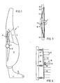
- Fig. 1 is a side view, partly in section, of a chair back according to the invention,
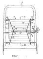
- Fig. 2 is a rear view of the fundamental structure of a chair back according to the invention,
- Fig. 3 is a sectional view taken on the line III-III in Fig. 2, and
- Fig. 4 is a part view, corresponding to Fig. 2, of an alternative embodiment of the invention.
- In the embodiment illustrated in Fig. 1, a chair back 1 forming part of an automobile seat has a
frame structure 2 covered by amoulded body 3. Themoulded body 3 has a back-support portion 4, which is located between outwardly projectingside parts 5, which support the user laterally. In turn, the back-support portion 4 is supported by asupport member 6 which is suspended in theframe structure 2 and which forms part of alumbar support 8, the position of which can be adjusted through a regulatingmeans 7. Arranged at the bottom of the chair back 1 are attachment means 9, for connecting the chair back to the seat-part of a chair. - As shown in Fig. 2, the
support member 6 is provided with two elongated, preferably rod-like side elements members 12. Each of theside elements springs 13, in a respectiveadjacent side part frame structure 2. In this way, thetransverse members 12, which may have the form of wires or straps, are placed under tension. - Co-acting with the
side element 10 is atensioning device 16, while afurther tensioning device 17 is arranged to co-act with theother side element 11. Each tensioning device includes an engagement means 18 having extending therefrom connectingdevices 19, each of said connecting devices being connected to a respective end of the side element. The twotensioning devices side elements lumbar support 8 comprising thetransverse members 12 extending between the side elements. Thetensioning devices rotatable shaft 21, which is located substantially on a level with the centre regions of the side elements and which is in screw-threaded engagement with the engaging.means 18 of each tensioning device. The screw threads are such that the two engagingmeans 18 are moved in opposite directions along theshaft 21, when said shaft is rotated. The regulatingmeans 7 is journalled in aholder 22 onside part 15, and is connected with the adjustingshaft 21 via atwistable connector 23, which permits a certain amount of mutual movement between the regulatingmeans 7 and the adjustingshaft 21. It will be understood that although only one regulatingmeans 7 is shown, theshaft 21 may have such a means on both ends thereof. - Normally, the
side elements springs 13 have the form of tension coil-springs, although it will be understood that other types of spring can be used, in suitable numbers. - Another type of
tensioning device 16 is illustrated in Fig. 4. In this embodiment, as distinct from what has previously been described, theengaging means 18 is non-rotatably mounted on the adjustingshaft 21. In this case, the connectingdevices 19 are so flexible as to be capable of being wound onto and unwound from the engaging means, as theshaft 21 is turned, so as to change the size of the arch. In this embodiment, theengaging means 18 may optionally comprise an actual part of therotatable shaft 21, and may then suitably be located immediately behind an associated side element. In order to hold the side elements outwardly arched, it is necessary with this embodiment to provide some form of locking means between theholder 22 and the regulatingmeans 7, for example in the form of a friction lock, to prevent accidental rotation of the adjustingshaft 21.
Claims (6)
Priority Applications (2)
| Application Number | Priority Date | Filing Date | Title |
|---|---|---|---|
| AT84850231T ATE37656T1 (en) | 1984-07-23 | 1984-07-23 | BACKREST WITH ADJUSTABLE LUMBAR SUPPORT. |
| DE8484850231T DE3474404D1 (en) | 1984-07-23 | 1984-07-23 | A chair back with adjustable lumbar support |
Applications Claiming Priority (1)
| Application Number | Priority Date | Filing Date | Title |
|---|---|---|---|
| SE8300421A SE445168B (en) | 1983-01-27 | 1983-01-27 | CHAIRS BACK, SPEC FOR A VEHICLE CHAIR |
Publications (2)
| Publication Number | Publication Date |
|---|---|
| EP0169293A1 true EP0169293A1 (en) | 1986-01-29 |
| EP0169293B1 EP0169293B1 (en) | 1988-10-05 |
Family
ID=20349787
Family Applications (1)
| Application Number | Title | Priority Date | Filing Date |
|---|---|---|---|
| EP84850231A Expired EP0169293B1 (en) | 1983-01-27 | 1984-07-23 | A chair back with adjustable lumbar support |
Country Status (3)
| Country | Link |
|---|---|
| US (1) | US4627661A (en) |
| EP (1) | EP0169293B1 (en) |
| SE (1) | SE445168B (en) |
Cited By (10)
| Publication number | Priority date | Publication date | Assignee | Title |
|---|---|---|---|---|
| WO1991001666A1 (en) * | 1989-08-04 | 1991-02-21 | Wilhelm Schuster | Cambering mechanism |
| EP0423079A1 (en) * | 1989-10-10 | 1991-04-17 | FIAT AUTO S.p.A. | A backrest having a profile variable with grid elements |
| EP0296938B1 (en) * | 1987-06-18 | 1991-06-05 | Bertrand Faure Automobile "Bfa" | Vehicle seat with adjustable lumbar support |
| WO1993013696A1 (en) * | 1992-01-20 | 1993-07-22 | Youngflex S.A. | Improvements in and relating to seat arrangements providing adjustable lumbar support |
| WO1993021800A1 (en) * | 1992-04-29 | 1993-11-11 | Bubb, Antony, John, Allen | Improvements in and relating to seat arrangements providing adjustable lumbar support |
| WO1993025404A1 (en) * | 1992-06-09 | 1993-12-23 | Pirelli Limited | Seat back with adjustable support |
| EP0754590A2 (en) * | 1995-07-19 | 1997-01-22 | LEAR CORPORATION ITALIA S.p.A. | Motor-vehicle seat |
| GB2333037A (en) * | 1997-12-18 | 1999-07-14 | Stadium Products Limited | Chair with lumbar support |
| US6631951B2 (en) | 2001-02-21 | 2003-10-14 | Schukra Of North America | Powered actuator for lumbar unit |
| US10427569B2 (en) | 2015-01-26 | 2019-10-01 | Kongsberg Automotive, Inc. | Adjustment mechanism for a seat |
Families Citing this family (54)
| Publication number | Priority date | Publication date | Assignee | Title |
|---|---|---|---|---|
| IT1211406B (en) * | 1987-10-16 | 1989-10-18 | Fiat Auto Spa | ADJUSTABLE BACKREST FOR DIVE VEHICLE SEATS, PARTICULARLY CARS |
| IT1219016B (en) * | 1988-02-12 | 1990-04-24 | Tis Tecnologia Innovazione Sti | SPRING AND LATERAL CONTAINMENT ELEMENT FOR A SEAT AND OR BACK OF A SEAT AND SEAT IN CORPORATE SUCH ELEMENT |
| IT1239943B (en) * | 1990-03-09 | 1993-11-27 | Lorenza Sessini | BEARING FOR ANATOMICAL SUPPORT, IN LUMBAR AND CERVICAL SPECIES, FOR SEAT BACKRESTS |
| US5076643A (en) * | 1990-08-20 | 1991-12-31 | Lear Seating Corporation | Lumbar support |
| DE4320105C1 (en) | 1993-06-17 | 1994-10-13 | Ameu Management Corp | Adjustment device for a flexurally elastic supporting element of a backrest |
| US5553919A (en) * | 1994-10-11 | 1996-09-10 | Excellence Lumbar Corporation | Scissor jack lumbar support |
| US6805680B2 (en) | 1994-12-09 | 2004-10-19 | Schukra-Geratebau Ag | Method for providing a massage on seats, and a device for implementing this method |
| US5651584A (en) * | 1995-04-24 | 1997-07-29 | L & P Property Management Company | Lumbar support structure for automotive vehicle |
| CA2181776A1 (en) | 1996-07-22 | 1998-01-23 | Christopher Cosentino | Shape-adjusting mechanism for backrest |
| GB2316604B (en) * | 1996-08-23 | 1998-10-14 | Youngflex Ag | Improved seat suspension arrangement and adjustment mechanism therefor |
| US5911477A (en) * | 1997-05-29 | 1999-06-15 | L&P Property Management Company | Lumbar support structure for automotive vehicle |
| DE19750116C2 (en) * | 1997-11-13 | 2002-11-07 | Faurecia Autositze Gmbh & Co | Adjustment mechanism for the lateral support areas of a seat, in particular of its backrest |
| US6053064A (en) * | 1998-05-01 | 2000-04-25 | L & P Property Management Company | Lumbar support screw actuator |
| EP1150592B1 (en) | 1999-02-12 | 2004-04-28 | Schukra of North America Ltd. | Adjustable back support for seats |
| CA2268046C (en) | 1999-04-07 | 2004-03-02 | Christopher Cosentino | Adjustment mechanism with slidable shaft |
| CA2268481C (en) | 1999-04-08 | 2004-06-22 | Tony Maier | Unitary adjustable seat basket |
| US6663177B2 (en) * | 2000-12-13 | 2003-12-16 | Lear Corporation | Advanced elastomeric integral suspension seating system |
| US6619739B2 (en) | 2001-03-01 | 2003-09-16 | L & P Property Management Company | Universal ergonomic support with self-contained actuator |
| US6758522B2 (en) | 2001-03-29 | 2004-07-06 | L&P Property Management Company | Apparatus and method for varying coefficients of friction in a variable apex back support |
| US6402246B1 (en) | 2001-04-11 | 2002-06-11 | L&P Property Management | Simplified strap lumbar support device |
| US7000986B2 (en) | 2001-09-28 | 2006-02-21 | Ficosa North America | Lumbar support apparatus |
| WO2003031222A1 (en) | 2001-10-11 | 2003-04-17 | L & P Property Mangement Company | Power lumbar mechanism |
| US6652028B2 (en) | 2001-11-02 | 2003-11-25 | L & P Property Management | Apparatus and method for lumbar support with variable apex |
| US6676214B2 (en) | 2001-11-16 | 2004-01-13 | L & P Property Management Company | Method and apparatus for lumbar support with integrated actuator housing |
| JP3975282B2 (en) * | 2001-11-29 | 2007-09-12 | テイ・エス テック株式会社 | Seat back tension structure |
| US6908152B2 (en) | 2001-12-14 | 2005-06-21 | L & P Property Management Company | Push lumbar support with flexible pressure surface |
| US6779844B2 (en) | 2001-12-14 | 2004-08-24 | L&P Propety Maqnagement Company | Arching lumbar support with weight distribution surface |
| US6652029B2 (en) | 2001-12-20 | 2003-11-25 | L & P Property Management Company | Unitized back plate and lumbar support |
| KR100461147B1 (en) * | 2002-10-12 | 2004-12-14 | 현대자동차주식회사 | Seat for preventing injury of neck |
| US7083232B2 (en) | 2002-11-01 | 2006-08-01 | L&P Property Management Company | Massage apparatus and method for lumbar support |
| US6908153B2 (en) | 2002-12-02 | 2005-06-21 | L&P Property Management Company | Power lumbar support cable apparatus and method |
| US7052087B2 (en) | 2002-12-09 | 2006-05-30 | L&P Property Management Company | Method and apparatus for a scissors ergonomic support |
| US6905170B2 (en) | 2003-01-22 | 2005-06-14 | L & P Property Management Company | Fold down seat lumbar support apparatus and method |
| US7140680B2 (en) | 2003-01-22 | 2006-11-28 | L&P Property Management Company | Fold down seat lumbar support apparatus and method |
| US7137664B2 (en) | 2003-01-22 | 2006-11-21 | L&P Property Management Company | Automatically actuating ergonomic support system for a fold down seat |
| JP2004229957A (en) * | 2003-01-31 | 2004-08-19 | Delta Tooling Co Ltd | Seat structure |
| CN1922416B (en) | 2004-02-06 | 2010-05-05 | L&P产权管理公司 | Drive mechanism |
| US7216933B2 (en) * | 2004-02-21 | 2007-05-15 | Armin Sander | Backrest, particularly for an office chair |
| US7252335B2 (en) * | 2004-03-12 | 2007-08-07 | L&P Property Management Company | Lumbar with flexwires in cross |
| CN100545000C (en) | 2004-07-30 | 2009-09-30 | L&P产权管理公司 | Modular lumbar support apparatus |
| US20060178603A1 (en) * | 2004-10-21 | 2006-08-10 | Popescu Horatiu M | Lumbar adjustable support integrated with massage system |
| EP1680983B1 (en) | 2005-01-12 | 2012-11-28 | L&P Swiss Holding Company | Seat structure comprising a coupling unit |
| PT1680984E (en) | 2005-01-12 | 2007-09-04 | L&P Swiss Holding Co | Lumbar support assembly and corresponding seat structure |
| PT1688065E (en) * | 2005-02-07 | 2008-12-26 | L&P Swiss Holding Co | Lumbar support device |
| US7490899B2 (en) | 2006-03-30 | 2009-02-17 | Schukra Of North America | Combination lumbar-bolster system |
| US20070239090A1 (en) * | 2006-03-31 | 2007-10-11 | Schukra Of North America | Massage System |
| CN101370409A (en) | 2006-12-11 | 2009-02-18 | 舒克拉北美有限公司 | Lumbar system for climate seating |
| US7703849B2 (en) * | 2006-12-22 | 2010-04-27 | B&B Innovators, Llc | Vertebral column support apparatus and method |
| US7984949B2 (en) | 2007-04-24 | 2011-07-26 | Schukra Of North America | Lumbar and bolster support for second row seat |
| CA2655083C (en) | 2008-02-22 | 2016-07-05 | Schukra Of North America | Constant pressure retreating lumbar system |
| US7905547B2 (en) * | 2008-03-09 | 2011-03-15 | Gm Global Technology Operations, Llc | Manipulable lumbar support utilizing active material actuation |
| JP6070601B2 (en) * | 2014-02-26 | 2017-02-01 | トヨタ自動車株式会社 | Vehicle seat |
| US9604560B1 (en) | 2015-11-13 | 2017-03-28 | Kongsberg Automotive, Inc. | Assembly for adjusting a lumbar region of a seat |
| US20230012911A1 (en) * | 2021-07-19 | 2023-01-19 | Pierre Heroux | Cushioned furntiure restoration kit |
Citations (3)
| Publication number | Priority date | Publication date | Assignee | Title |
|---|---|---|---|---|
| FR480672A (en) * | 1916-01-14 | 1916-09-07 | Alton J Poler | Flexible chair back, can be adjusted to conform to the shape of the chair occupant's back |
| US3195955A (en) * | 1963-08-05 | 1965-07-20 | Flex O Lators | Seat back structure |
| DE2935352A1 (en) * | 1978-09-06 | 1980-03-27 | Steyr Daimler Puch Ag | Contour control for seat back - incorporates flexible support plate and tensioning ties |
Family Cites Families (9)
| Publication number | Priority date | Publication date | Assignee | Title |
|---|---|---|---|---|
| US1182854A (en) * | 1915-05-10 | 1916-05-09 | Albert J Coe | Flexible back adjustment for chairs. |
| DE1274003B (en) * | 1961-09-15 | 1968-07-25 | Volkswagenwerk Ag | Backrest with adjustable back support for vehicle seats |
| GB1365348A (en) * | 1971-12-16 | 1974-09-04 | Vauxhall Motors Ltd | Vehicle seat |
| DE2541559A1 (en) * | 1975-09-18 | 1977-03-24 | Bama Bueroeinrichtungs Ges Mbh | Adjustable lumbar support for seat - has two arm linkage to seat frame for vertical and horizontal movement |
| GB1536132A (en) * | 1976-04-15 | 1978-12-20 | Pullman Flexolators Ltd | Seats |
| AT358767B (en) * | 1978-06-23 | 1980-09-25 | Schuster Wilhelm | BENDABLE ELASTIC SUPPORT |
| AT368958B (en) * | 1979-01-24 | 1982-11-25 | Steyr Daimler Puch Ag | BACKREST, ESPECIALLY FOR MOTOR VEHICLE SEATS |
| DE2947472A1 (en) * | 1979-01-24 | 1980-08-07 | Steyr Daimler Puch Ag | Motor vehicle variable shape seat back - has flexible plate tensioned by cable adjusters |
| FR2465442A1 (en) * | 1979-09-25 | 1981-03-27 | Faure Bertrand | IMPROVEMENTS TO SEAT RECORDS, IN PARTICULAR FOR VEHICLES |
-
1983
- 1983-01-27 SE SE8300421A patent/SE445168B/en not_active IP Right Cessation
-
1984
- 1984-07-23 EP EP84850231A patent/EP0169293B1/en not_active Expired
- 1984-07-25 US US06/634,229 patent/US4627661A/en not_active Expired - Lifetime
Patent Citations (3)
| Publication number | Priority date | Publication date | Assignee | Title |
|---|---|---|---|---|
| FR480672A (en) * | 1916-01-14 | 1916-09-07 | Alton J Poler | Flexible chair back, can be adjusted to conform to the shape of the chair occupant's back |
| US3195955A (en) * | 1963-08-05 | 1965-07-20 | Flex O Lators | Seat back structure |
| DE2935352A1 (en) * | 1978-09-06 | 1980-03-27 | Steyr Daimler Puch Ag | Contour control for seat back - incorporates flexible support plate and tensioning ties |
Cited By (16)
| Publication number | Priority date | Publication date | Assignee | Title |
|---|---|---|---|---|
| EP0296938B1 (en) * | 1987-06-18 | 1991-06-05 | Bertrand Faure Automobile "Bfa" | Vehicle seat with adjustable lumbar support |
| GR900100678A (en) * | 1989-08-04 | 1992-01-20 | Wilhelm Schuster Ing | Curve mechanics |
| AT396734B (en) * | 1989-08-04 | 1993-11-25 | Schuster Wilhelm | Curving mechanism |
| WO1991001666A1 (en) * | 1989-08-04 | 1991-02-21 | Wilhelm Schuster | Cambering mechanism |
| EP0423079A1 (en) * | 1989-10-10 | 1991-04-17 | FIAT AUTO S.p.A. | A backrest having a profile variable with grid elements |
| US5449219A (en) * | 1992-01-20 | 1995-09-12 | Youngflex, S.A. | Seat arrangements providing adjustable lumbar support |
| WO1993013696A1 (en) * | 1992-01-20 | 1993-07-22 | Youngflex S.A. | Improvements in and relating to seat arrangements providing adjustable lumbar support |
| EP0552904A1 (en) * | 1992-01-20 | 1993-07-28 | Youngflex S.A. | Improvements in and relating to seat arrangements providing adjustable lumbar support |
| WO1993021800A1 (en) * | 1992-04-29 | 1993-11-11 | Bubb, Antony, John, Allen | Improvements in and relating to seat arrangements providing adjustable lumbar support |
| WO1993025404A1 (en) * | 1992-06-09 | 1993-12-23 | Pirelli Limited | Seat back with adjustable support |
| EP0754590A2 (en) * | 1995-07-19 | 1997-01-22 | LEAR CORPORATION ITALIA S.p.A. | Motor-vehicle seat |
| EP0754590A3 (en) * | 1995-07-19 | 1997-10-01 | Lear Corp Italia Spa | Motor-vehicle seat |
| GB2333037A (en) * | 1997-12-18 | 1999-07-14 | Stadium Products Limited | Chair with lumbar support |
| GB2333037B (en) * | 1997-12-18 | 2002-06-12 | Stadium Products Ltd | Simulated fabric-covered article |
| US6631951B2 (en) | 2001-02-21 | 2003-10-14 | Schukra Of North America | Powered actuator for lumbar unit |
| US10427569B2 (en) | 2015-01-26 | 2019-10-01 | Kongsberg Automotive, Inc. | Adjustment mechanism for a seat |
Also Published As
| Publication number | Publication date |
|---|---|
| SE445168B (en) | 1986-06-09 |
| SE8300421D0 (en) | 1983-01-27 |
| SE8300421L (en) | 1984-07-28 |
| EP0169293B1 (en) | 1988-10-05 |
| US4627661A (en) | 1986-12-09 |
Similar Documents
| Publication | Publication Date | Title |
|---|---|---|
| EP0169293A1 (en) | A chair back with adjustable lumbar support | |
| US4880271A (en) | Adjustable lumbar support | |
| JP5041510B2 (en) | Vehicle seat | |
| US6883867B2 (en) | Device for adjusting a flexible support element of a backrest | |
| EP0322535A1 (en) | Adjustable lumbar support | |
| US7011369B2 (en) | Integrated adjustable lumbar support and trim attachment system | |
| US5092654A (en) | Seatback spring device | |
| CN101087546B (en) | Lumbar support assembly and corresponding seat structure | |
| US3559853A (en) | Camera strap with free-floating loops at both ends | |
| US20100066145A1 (en) | Vehicle seat | |
| US5501508A (en) | Device for supporting the user of a chair | |
| EP0220762B1 (en) | Device for adjusting flexible laths relative to a bed frame | |
| US20040066075A1 (en) | Structure for adjusting backrest for collapsible chairs | |
| RU2004126402A (en) | BACKREST | |
| EP2450226A1 (en) | Child seat | |
| US4682763A (en) | Flexible mounting | |
| US4736984A (en) | Pivot assembly for reclining chair with rocking feature | |
| US7614695B2 (en) | Seat back structure and seat for vehicle | |
| JP2003276559A (en) | Shoulder pad for seat belt of vehicle | |
| US7090301B2 (en) | Apparatus and method for lumbar support structure | |
| JPS6137212A (en) | Backrest of chair | |
| CA1235994A (en) | Chair back with adjustable lumbar support | |
| EP3768553B1 (en) | Adjustable lumbar support for a vehicle seat | |
| GB2335844A (en) | Seat assembly providing adjustable lumbar support | |
| JPS59106328A (en) | Support mechanism |
Legal Events
| Date | Code | Title | Description |
|---|---|---|---|
| PUAI | Public reference made under article 153(3) epc to a published international application that has entered the european phase |
Free format text: ORIGINAL CODE: 0009012 |
|
| 17P | Request for examination filed |
Effective date: 19850927 |
|
| AK | Designated contracting states |
Designated state(s): AT BE CH DE FR GB IT LI LU NL SE |
|
| 17Q | First examination report despatched |
Effective date: 19870123 |
|
| GRAA | (expected) grant |
Free format text: ORIGINAL CODE: 0009210 |
|
| AK | Designated contracting states |
Kind code of ref document: B1 Designated state(s): AT BE CH DE FR GB IT LI LU NL SE |
|
| PG25 | Lapsed in a contracting state [announced via postgrant information from national office to epo] |
Ref country code: SE Effective date: 19881005 |
|
| REF | Corresponds to: |
Ref document number: 37656 Country of ref document: AT Date of ref document: 19881015 Kind code of ref document: T |
|
| REF | Corresponds to: |
Ref document number: 3474404 Country of ref document: DE Date of ref document: 19881110 |
|
| ITF | It: translation for a ep patent filed |
Owner name: BARZANO' E ZANARDO MILANO S.P.A. |
|
| ET | Fr: translation filed | ||
| PLBE | No opposition filed within time limit |
Free format text: ORIGINAL CODE: 0009261 |
|
| STAA | Information on the status of an ep patent application or granted ep patent |
Free format text: STATUS: NO OPPOSITION FILED WITHIN TIME LIMIT |
|
| 26N | No opposition filed | ||
| ITTA | It: last paid annual fee | ||
| EPTA | Lu: last paid annual fee | ||
| PGFP | Annual fee paid to national office [announced via postgrant information from national office to epo] |
Ref country code: AT Payment date: 20000712 Year of fee payment: 17 |
|
| PGFP | Annual fee paid to national office [announced via postgrant information from national office to epo] |
Ref country code: LU Payment date: 20000724 Year of fee payment: 17 Ref country code: DE Payment date: 20000724 Year of fee payment: 17 |
|
| PGFP | Annual fee paid to national office [announced via postgrant information from national office to epo] |
Ref country code: CH Payment date: 20000726 Year of fee payment: 17 |
|
| PG25 | Lapsed in a contracting state [announced via postgrant information from national office to epo] |
Ref country code: LU Free format text: LAPSE BECAUSE OF NON-PAYMENT OF DUE FEES Effective date: 20010723 Ref country code: AT Free format text: LAPSE BECAUSE OF NON-PAYMENT OF DUE FEES Effective date: 20010723 |
|
| PG25 | Lapsed in a contracting state [announced via postgrant information from national office to epo] |
Ref country code: LI Free format text: LAPSE BECAUSE OF NON-PAYMENT OF DUE FEES Effective date: 20010731 Ref country code: CH Free format text: LAPSE BECAUSE OF NON-PAYMENT OF DUE FEES Effective date: 20010731 |
|
| PGFP | Annual fee paid to national office [announced via postgrant information from national office to epo] |
Ref country code: FR Payment date: 20011025 Year of fee payment: 18 |
|
| REG | Reference to a national code |
Ref country code: GB Ref legal event code: IF02 |
|
| REG | Reference to a national code |
Ref country code: CH Ref legal event code: PL |
|
| PG25 | Lapsed in a contracting state [announced via postgrant information from national office to epo] |
Ref country code: DE Free format text: LAPSE BECAUSE OF NON-PAYMENT OF DUE FEES Effective date: 20020501 |
|
| PG25 | Lapsed in a contracting state [announced via postgrant information from national office to epo] |
Ref country code: FR Free format text: LAPSE BECAUSE OF NON-PAYMENT OF DUE FEES Effective date: 20030331 |
|
| REG | Reference to a national code |
Ref country code: FR Ref legal event code: ST |
|
| PGFP | Annual fee paid to national office [announced via postgrant information from national office to epo] |
Ref country code: GB Payment date: 20030723 Year of fee payment: 20 |
|
| PGFP | Annual fee paid to national office [announced via postgrant information from national office to epo] |
Ref country code: NL Payment date: 20030730 Year of fee payment: 20 |
|
| PGFP | Annual fee paid to national office [announced via postgrant information from national office to epo] |
Ref country code: BE Payment date: 20030926 Year of fee payment: 20 |
|
| PG25 | Lapsed in a contracting state [announced via postgrant information from national office to epo] |
Ref country code: GB Free format text: LAPSE BECAUSE OF EXPIRATION OF PROTECTION Effective date: 20040722 |
|
| PG25 | Lapsed in a contracting state [announced via postgrant information from national office to epo] |
Ref country code: NL Free format text: LAPSE BECAUSE OF EXPIRATION OF PROTECTION Effective date: 20040723 |
|
| BE20 | Be: patent expired |
Owner name: *BE-GE STOLINDUSTRI A.B. Effective date: 20040723 |
|
| REG | Reference to a national code |
Ref country code: GB Ref legal event code: PE20 |
|
| NLV7 | Nl: ceased due to reaching the maximum lifetime of a patent |