EP0168992B1 - Schläger für Ballspiele - Google Patents
Schläger für Ballspiele Download PDFInfo
- Publication number
- EP0168992B1 EP0168992B1 EP85304470A EP85304470A EP0168992B1 EP 0168992 B1 EP0168992 B1 EP 0168992B1 EP 85304470 A EP85304470 A EP 85304470A EP 85304470 A EP85304470 A EP 85304470A EP 0168992 B1 EP0168992 B1 EP 0168992B1
- Authority
- EP
- European Patent Office
- Prior art keywords
- head
- core
- tubular projection
- holes
- frame
- Prior art date
- Legal status (The legal status is an assumption and is not a legal conclusion. Google has not performed a legal analysis and makes no representation as to the accuracy of the status listed.)
- Expired
Links
- 239000000463 material Substances 0.000 claims abstract description 24
- 229920001169 thermoplastic Polymers 0.000 claims abstract description 23
- 239000004416 thermosoftening plastic Substances 0.000 claims abstract description 23
- 238000000465 moulding Methods 0.000 claims abstract description 20
- 230000003014 reinforcing effect Effects 0.000 claims abstract description 8
- 238000001746 injection moulding Methods 0.000 claims abstract description 7
- 239000011162 core material Substances 0.000 claims description 36
- 238000002844 melting Methods 0.000 claims description 8
- 230000008018 melting Effects 0.000 claims description 8
- 239000012779 reinforcing material Substances 0.000 claims description 8
- 238000000034 method Methods 0.000 claims description 4
- 229920006380 polyphenylene oxide Polymers 0.000 claims description 3
- DHKHKXVYLBGOIT-UHFFFAOYSA-N 1,1-Diethoxyethane Chemical compound CCOC(C)OCC DHKHKXVYLBGOIT-UHFFFAOYSA-N 0.000 claims description 2
- OKTJSMMVPCPJKN-UHFFFAOYSA-N Carbon Chemical compound [C] OKTJSMMVPCPJKN-UHFFFAOYSA-N 0.000 claims description 2
- 239000004952 Polyamide Substances 0.000 claims description 2
- 239000011354 acetal resin Substances 0.000 claims description 2
- 239000004676 acrylonitrile butadiene styrene Substances 0.000 claims description 2
- 239000004760 aramid Substances 0.000 claims description 2
- 229920003235 aromatic polyamide Polymers 0.000 claims description 2
- 229910052799 carbon Inorganic materials 0.000 claims description 2
- 238000004519 manufacturing process Methods 0.000 claims description 2
- 239000000203 mixture Substances 0.000 claims description 2
- 229920002647 polyamide Polymers 0.000 claims description 2
- 229920000515 polycarbonate Polymers 0.000 claims description 2
- 239000004417 polycarbonate Substances 0.000 claims description 2
- 229920006324 polyoxymethylene Polymers 0.000 claims description 2
- 239000000835 fiber Substances 0.000 claims 2
- XECAHXYUAAWDEL-UHFFFAOYSA-N acrylonitrile butadiene styrene Chemical compound C=CC=C.C=CC#N.C=CC1=CC=CC=C1 XECAHXYUAAWDEL-UHFFFAOYSA-N 0.000 claims 1
- 229920000122 acrylonitrile butadiene styrene Polymers 0.000 claims 1
- 239000003365 glass fiber Substances 0.000 claims 1
- -1 poly(phenylene oxide) Polymers 0.000 claims 1
- 238000010276 construction Methods 0.000 description 4
- 238000002347 injection Methods 0.000 description 4
- 239000007924 injection Substances 0.000 description 4
- 235000009854 Cucurbita moschata Nutrition 0.000 description 2
- 240000001980 Cucurbita pepo Species 0.000 description 2
- 235000009852 Cucurbita pepo Nutrition 0.000 description 2
- 239000011159 matrix material Substances 0.000 description 2
- 229910001092 metal group alloy Inorganic materials 0.000 description 2
- 235000020354 squash Nutrition 0.000 description 2
- 238000005299 abrasion Methods 0.000 description 1
- 230000015572 biosynthetic process Effects 0.000 description 1
- 239000011521 glass Substances 0.000 description 1
- 238000010348 incorporation Methods 0.000 description 1
- 238000005304 joining Methods 0.000 description 1
- 230000013011 mating Effects 0.000 description 1
- 239000002184 metal Substances 0.000 description 1
- 239000004033 plastic Substances 0.000 description 1
- 229920003023 plastic Polymers 0.000 description 1
- 230000002787 reinforcement Effects 0.000 description 1
- 239000011347 resin Substances 0.000 description 1
- 229920005989 resin Polymers 0.000 description 1
- 238000005728 strengthening Methods 0.000 description 1
Images

Classifications
-
- A—HUMAN NECESSITIES
- A63—SPORTS; GAMES; AMUSEMENTS
- A63B—APPARATUS FOR PHYSICAL TRAINING, GYMNASTICS, SWIMMING, CLIMBING, OR FENCING; BALL GAMES; TRAINING EQUIPMENT
- A63B49/00—Stringed rackets, e.g. for tennis
- A63B49/02—Frames
-
- B—PERFORMING OPERATIONS; TRANSPORTING
- B29—WORKING OF PLASTICS; WORKING OF SUBSTANCES IN A PLASTIC STATE IN GENERAL
- B29C—SHAPING OR JOINING OF PLASTICS; SHAPING OF MATERIAL IN A PLASTIC STATE, NOT OTHERWISE PROVIDED FOR; AFTER-TREATMENT OF THE SHAPED PRODUCTS, e.g. REPAIRING
- B29C33/00—Moulds or cores; Details thereof or accessories therefor
- B29C33/0033—Moulds or cores; Details thereof or accessories therefor constructed for making articles provided with holes
-
- A—HUMAN NECESSITIES
- A63—SPORTS; GAMES; AMUSEMENTS
- A63B—APPARATUS FOR PHYSICAL TRAINING, GYMNASTICS, SWIMMING, CLIMBING, OR FENCING; BALL GAMES; TRAINING EQUIPMENT
- A63B49/00—Stringed rackets, e.g. for tennis
- A63B49/02—Frames
- A63B49/022—String guides on frames, e.g. grommets
-
- B—PERFORMING OPERATIONS; TRANSPORTING
- B29—WORKING OF PLASTICS; WORKING OF SUBSTANCES IN A PLASTIC STATE IN GENERAL
- B29C—SHAPING OR JOINING OF PLASTICS; SHAPING OF MATERIAL IN A PLASTIC STATE, NOT OTHERWISE PROVIDED FOR; AFTER-TREATMENT OF THE SHAPED PRODUCTS, e.g. REPAIRING
- B29C45/00—Injection moulding, i.e. forcing the required volume of moulding material through a nozzle into a closed mould; Apparatus therefor
- B29C45/17—Component parts, details or accessories; Auxiliary operations
- B29C45/26—Moulds
- B29C45/2628—Moulds with mould parts forming holes in or through the moulded article, e.g. for bearing cages
-
- B—PERFORMING OPERATIONS; TRANSPORTING
- B29—WORKING OF PLASTICS; WORKING OF SUBSTANCES IN A PLASTIC STATE IN GENERAL
- B29C—SHAPING OR JOINING OF PLASTICS; SHAPING OF MATERIAL IN A PLASTIC STATE, NOT OTHERWISE PROVIDED FOR; AFTER-TREATMENT OF THE SHAPED PRODUCTS, e.g. REPAIRING
- B29C45/00—Injection moulding, i.e. forcing the required volume of moulding material through a nozzle into a closed mould; Apparatus therefor
- B29C45/17—Component parts, details or accessories; Auxiliary operations
- B29C45/40—Removing or ejecting moulded articles
- B29C45/44—Removing or ejecting moulded articles for undercut articles
- B29C45/4457—Removing or ejecting moulded articles for undercut articles using fusible, soluble or destructible cores
-
- B—PERFORMING OPERATIONS; TRANSPORTING
- B29—WORKING OF PLASTICS; WORKING OF SUBSTANCES IN A PLASTIC STATE IN GENERAL
- B29C—SHAPING OR JOINING OF PLASTICS; SHAPING OF MATERIAL IN A PLASTIC STATE, NOT OTHERWISE PROVIDED FOR; AFTER-TREATMENT OF THE SHAPED PRODUCTS, e.g. REPAIRING
- B29C33/00—Moulds or cores; Details thereof or accessories therefor
- B29C33/44—Moulds or cores; Details thereof or accessories therefor with means for, or specially constructed to facilitate, the removal of articles, e.g. of undercut articles
- B29C33/52—Moulds or cores; Details thereof or accessories therefor with means for, or specially constructed to facilitate, the removal of articles, e.g. of undercut articles soluble or fusible
-
- B—PERFORMING OPERATIONS; TRANSPORTING
- B29—WORKING OF PLASTICS; WORKING OF SUBSTANCES IN A PLASTIC STATE IN GENERAL
- B29C—SHAPING OR JOINING OF PLASTICS; SHAPING OF MATERIAL IN A PLASTIC STATE, NOT OTHERWISE PROVIDED FOR; AFTER-TREATMENT OF THE SHAPED PRODUCTS, e.g. REPAIRING
- B29C45/00—Injection moulding, i.e. forcing the required volume of moulding material through a nozzle into a closed mould; Apparatus therefor
- B29C45/0005—Injection moulding, i.e. forcing the required volume of moulding material through a nozzle into a closed mould; Apparatus therefor using fibre reinforcements
-
- B—PERFORMING OPERATIONS; TRANSPORTING
- B29—WORKING OF PLASTICS; WORKING OF SUBSTANCES IN A PLASTIC STATE IN GENERAL
- B29L—INDEXING SCHEME ASSOCIATED WITH SUBCLASS B29C, RELATING TO PARTICULAR ARTICLES
- B29L2031/00—Other particular articles
- B29L2031/52—Sports equipment ; Games; Articles for amusement; Toys
- B29L2031/5245—Rackets
Definitions
- This invention relates to rackets for use in games, for example tennis, squash and badminton and is particularly concerned with the construction of the frames of these rackets.
- thermoplastics material reinforced with short filament reinforcing material is mean a reinforced thermoplastics material in which the reinforcements are in the form of short discrete lengths of fibre-reinforcing material randomly dispersed in the thermoplastics resin matrix.
- the racket constructions so described in GB-A-2 015 886 are a significant step forward in that they provide the first really successful commercial rackets of hollow frame construction made by an injection moulding technique.
- the hollow frame is reinforced by integrally-moulded internal support means - usually in the form of pillars - joining the outer wall to the inner wall of the head of the frame. These pillars support the walls and provide strength in the moulded product to resist the considerable forces exerted on the hollow frame, particularly by the tension of the racket strings.
- the total force exerted by the strings on the hollow frame can be considerable, e.g. up to a total of 500 Kg force in the two perpendicular directions of the strings, i.e. longitudinal and transverse string directions.
- the present invention aims to provide alternative.
- Advantageous frame constructions whereby hollow injection-moulded racket frames of reinforced thermoplastics material may be made without internal support pillars passing through the frame from the outer to the inner wall so that improved moulding techniques may be employed.
- the invention provides a games racket frame in which the frame comprises a head and a shaft, at least the head being a hollow injection moulding of thermoplastics material reinforced with short filament reinforcing material, as herein defined, which contains integrally-moulded stringing holes, the holes being in opposed pairs, the first of each pair being in the wall of the moulding which lies at the inner circumference of the head and the second of each pair being in the wall of the moulding which lies at the outer circumference of the head, each first hole being defined by an integrally-moulded reinforcing first tubular projection or apertured boss which projects inside the hollow frame and each second hole being defined by an integrally-moulded reinforcing second tubular projection or apertured boss, the first and second tubular projections or apertured bosses projecting inwardly of the hollow frame towards each other but not meeting, the second tubular projection or apertured boss defining a larger area hole than the first.
- the invention provides a games racket comprising a strung frame of the type of the immediately preceding paragraph.
- the racket frame is provided with strengthening means provided at the stringing holes and extending inside the hollow frame so that the head of the frame is provided with pairs of tubular projection bosses (tubular projections hereafter for convenience) projecting inwardly towards each other but not meeting, i.e. the total length of projection of the pair of tubular projections is less than the transverse width of the hollow moulding at that point.
- a tubular projection on the inner wall will be referred to as a first tubular projection and a tubular projection on the outer wall as a second tubular projection.
- the bore of the tubular projections on the outer circumference of the head, i.e. the second tubular projections is preferably radiussed at its outer end so as to provide guidance for the strings and to protect them against sharp edges.
- the inner end of the firsttubular projections may be radiussed.
- the two tubular projections may be of equal length, i.e. may project inwardly for an equal distance but this is not essential and it may be preferred, for example, that the second tubular projection projects further inwardly than the first.
- the overall size of the tubular projections in order to provide adequate strength will of course depend on the type of racket frame in question, e.g. whether for tennis, badminton or squash, and will also depend on the wall thickness used, this again being determined by the envisaged use of the frame.
- the average skilled man of the art will readily be able to determine sizes satisfactory for his purpose but the dimensions given below with reference to the accompanying drawings may be considered illustrative by way of exemplification for a tennis racket frame.
- the racket frames of the invention are preferably moulded from reinforced polyamide although other thermoplastics polymeric material may be used, e.g. polycarbonate, acrylonitrile-butadiene-styrene (ABS), acetal resin and poly-(phenylene oxide) (PPO) may be used.
- thermoplastics polymeric material e.g. polycarbonate, acrylonitrile-butadiene-styrene (ABS), acetal resin and poly-(phenylene oxide) (PPO) may be used.
- thermoplastics material used is preferably reinforced with from 10% to 40% by weight of carbon fibres based on total weight of the reinforced matrix.
- glass or aromatic polyamide (e.g. Kevlar-Registered Trade Mark) fibres may be used or mixtures of any of these reinforcing fibres may be used.
- the transverse sectional shape of the frame may be any desired shape, for example circular, oval or rectangular.
- the latter may be preferred as its box-like section can give very high stiffness and strength to weight ratios.
- alongitudinally-extending groove or channel may be formed in the outer face of the wall of the frame which is to lie on the outer circumference of the head.
- the strings of the racket may then be recessed in this groove to safeguard them from abrasion.
- Racket frames of the invention can be made by an injection-moulding process involving a destructible core and it is preferred to use a core that can be melted below the softening point of the set plastics material of the frame.
- a core of this type in the moulding of a hollow article made from thermoplastics material is known and is described for example in GB-A-828,685.
- the principle involved is to make an appropriately-shaped core of fusible material (metal alloy in GB-A-828,685) whose melting point is lower than the temperature achieved in the injection-moulding cycle. Due to the thermal conductivity of the core, the moulding is effected before the metal reaches its melting point. Alternatively, the core can be cooled by heat exchange during the moulding cycle to prevent its melting. Once the moulded article has set, the temperature can be raised sufficiently to melt the core but insufficiently to melt or distort the moulding.
- the invention provides a method of making a frame for a games racket, the frame comprising a head and a shaft, which method comprises the following steps:
- the fusible core is preferably of a low melting point metal alloy.
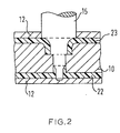
- a fusible core 10 is first made having a configuration corresponding to the desired internal configuration of the eventual head of the racket.
- a stepped bore 11 is formed through the core at each desired stringing location.
- Core 10 is placed in a suitable injection mould 12 and is spaced from the interior walls of the mould by conventional spacing means (not shown) to define gaps 13 and 14 corresponding to the desired walls at the inner circumference and outer circumference respectively of the head.
- a double-stepped pin 15 is inserted through each bore 11 of the core.
- Portion 16 of the pin 15 corresponds to the desired second tubular projection of the product and has radiussed shoulders 17.
- a first step 18 on the pin then leads to its middle portion 19, which portion locates tightly in the bore 11 of core 10. (Portion 19 and its corresponding portion of bore 11 have a mating slight taper towards the narrower end of the pin. This is not shown in the drawings).
- a second step 20 (radiussed) leads to portion 21 of the pin, which corresponds to the desired first tubular projection of the product.
- portion 21 locates in a suitable recess in the wall of mould 12.
- the mould pin When the frame has set, the mould pin can be removed and the fusible core can be melted out after removal of the moulding from the mould. This stage is shown in Figures 3 and 4.
- First tubular projection 24 has been formed on the inner wall 22 of the frame and second tubular projection 25 has been formed on outer wall 23.
- Tubular projection 24 is radiussed at its inner end and tubular projection 25 is radiussed at its outer end.
- the two projections define an opposed pair of stringing holes through which a string may be passed through the frame.
- second stringing hole 26 (defined by tubular projection 25) is of elliptical shape with its major axis along the circumferential axis of the head whereas first stringing hole 27 (shown dotted and defined by tubular projection 24) is circular.
- the minor axis of elipse 26 is the same dimension as the diameter of hole 27.
- areas 28 and 29 of elipse 27 correspond to the radiussed portion 17 of pin 15.
- the frame may have a wall thickness of 2.5 mm, the internal diameter of the first (circular) tubular projection is 2.5 mm and its length is 5 mm including the wall thickness of the frame.
- the internal diameter of the second tubular projection when circular is 4.5 mm and its length is 6 mm including the wall thickness of the frame.
- the overall thickness of the section of the frame, i.e. its transverse width, is 15 mm so that there is a gap of 4 mm between the two tubular projections inside the frame.
- the second tubular projection is elliptical its major axis may be 5 mm long and its minor axis 2.5 mm.
- the fusible cores employed can conveniently be shaped so that the shaft and handle portion of the frame are formed as an integral moulding with the head.
- Shaft and handle shapes as desired can readily be formed but have not been described above as they can be designed as required by the skilled man of the art.
- tubular projections need not be cylindrical or elliptical in shape and that other shapes could be used as desired.
- a combination of shapes can be used, if desired so that, as exemplified above, the second tubular projections are elliptical in plan form and the first tubular projections are circular in plan form.
- the mould pin arrangement described above is also very advantageous in that the use of stepped pins enables both tubular projections to be formed by a single pin that is withdrawn in one direction. Clearly this leads to relative simplicity of mould design. Also the series of pins being located tightly within their respective bores in the mould core means that there is a positive location at each hole so that there is excellent resistance to the considerable pressure of the injected thermoplastics material. Hence a product of very uniform wall thickness can be achieved. This enables thinner-walled products to be made to a higher standard of uniformity and hence enables lighter products to be made.
Landscapes
- Engineering & Computer Science (AREA)
- Mechanical Engineering (AREA)
- Health & Medical Sciences (AREA)
- General Health & Medical Sciences (AREA)
- Physical Education & Sports Medicine (AREA)
- Manufacturing & Machinery (AREA)
- Transition And Organic Metals Composition Catalysts For Addition Polymerization (AREA)
- Addition Polymer Or Copolymer, Post-Treatments, Or Chemical Modifications (AREA)
- Injection Moulding Of Plastics Or The Like (AREA)
- Moulds For Moulding Plastics Or The Like (AREA)
- Laminated Bodies (AREA)
- Moulding By Coating Moulds (AREA)
Claims (12)
dadurch gekennzeichnet, dass die Formstifte (15) eine solche Grösse haben, dass sie ihre entsprechenden Kernlöcher (11) über einen Teil ihrer Länge vollständig ausfüllen, und so geformt sind, dass sie es dem thermoplastischen Material gestatten, einen rohrförmigen Verstärkungsvorsprung zu bilden, der an jeder Bespannungslochstelle in der Formlingswand am Innenumfang und am Aussenumfang des Kopfes in das Innere des hohlen Rahmens ragt.
Priority Applications (1)
| Application Number | Priority Date | Filing Date | Title |
|---|---|---|---|
| AT85304470T ATE36649T1 (de) | 1984-07-17 | 1985-06-24 | Schlaeger fuer ballspiele. |
Applications Claiming Priority (2)
| Application Number | Priority Date | Filing Date | Title |
|---|---|---|---|
| GB8418192 | 1984-07-17 | ||
| GB848418192A GB8418192D0 (en) | 1984-07-17 | 1984-07-17 | Games racket |
Publications (3)
| Publication Number | Publication Date |
|---|---|
| EP0168992A2 EP0168992A2 (de) | 1986-01-22 |
| EP0168992A3 EP0168992A3 (en) | 1986-10-08 |
| EP0168992B1 true EP0168992B1 (de) | 1988-08-24 |
Family
ID=10564013
Family Applications (1)
| Application Number | Title | Priority Date | Filing Date |
|---|---|---|---|
| EP85304470A Expired EP0168992B1 (de) | 1984-07-17 | 1985-06-24 | Schläger für Ballspiele |
Country Status (9)
| Country | Link |
|---|---|
| EP (1) | EP0168992B1 (de) |
| JP (1) | JPS6145782A (de) |
| KR (1) | KR860000875A (de) |
| AT (1) | ATE36649T1 (de) |
| AU (1) | AU579382B2 (de) |
| DE (1) | DE3564534D1 (de) |
| ES (1) | ES296667Y (de) |
| GB (1) | GB8418192D0 (de) |
| ZA (1) | ZA855014B (de) |
Families Citing this family (4)
| Publication number | Priority date | Publication date | Assignee | Title |
|---|---|---|---|---|
| GB8706234D0 (en) * | 1987-03-17 | 1987-04-23 | Dunlop Ltd | Games racket |
| JPH02157495A (ja) * | 1988-12-09 | 1990-06-18 | Fujitsu General Ltd | 空気調和機のファンモータの異常検出方法 |
| JP2563236B2 (ja) * | 1993-06-11 | 1996-12-11 | 株式会社アシックス | ラケットフレームの製造方法 |
| JP3889940B2 (ja) | 2001-06-13 | 2007-03-07 | 株式会社東海理化電機製作所 | 金型装置、金型装置の使用方法、及び金型装置の共用方法 |
Family Cites Families (5)
| Publication number | Priority date | Publication date | Assignee | Title |
|---|---|---|---|---|
| FR2270908A1 (en) * | 1973-12-19 | 1975-12-12 | Martel Rene | Moulded resin tennis racket frame - has hollow interfitting string-receiving bosses in two U-section head elements |
| FR2359618A1 (fr) * | 1976-07-28 | 1978-02-24 | Rossignol Sa | Raquette de tennis |
| CH614380A5 (de) * | 1976-07-28 | 1979-11-30 | Rossignol Sa | |
| US4066260A (en) * | 1976-10-15 | 1978-01-03 | Rodgers Jr Robert E | Metal-plastic composite racquet |
| GB2015886B (en) * | 1978-03-07 | 1982-05-12 | Dunlop Ltd | Games rackets |
-
1984
- 1984-07-17 GB GB848418192A patent/GB8418192D0/en active Pending
-
1985
- 1985-06-24 EP EP85304470A patent/EP0168992B1/de not_active Expired
- 1985-06-24 DE DE8585304470T patent/DE3564534D1/de not_active Expired
- 1985-06-24 AT AT85304470T patent/ATE36649T1/de not_active IP Right Cessation
- 1985-06-28 AU AU44427/85A patent/AU579382B2/en not_active Ceased
- 1985-07-03 ZA ZA855014A patent/ZA855014B/xx unknown
- 1985-07-16 KR KR1019850005073A patent/KR860000875A/ko not_active Withdrawn
- 1985-07-16 ES ES1985296667U patent/ES296667Y/es not_active Expired
- 1985-07-17 JP JP60157981A patent/JPS6145782A/ja active Pending
Also Published As
| Publication number | Publication date |
|---|---|
| ZA855014B (en) | 1987-01-28 |
| AU579382B2 (en) | 1988-11-24 |
| KR860000875A (ko) | 1986-02-20 |
| EP0168992A2 (de) | 1986-01-22 |
| AU4442785A (en) | 1986-01-23 |
| ES296667U (es) | 1987-12-16 |
| EP0168992A3 (en) | 1986-10-08 |
| ES296667Y (es) | 1988-05-16 |
| DE3564534D1 (en) | 1988-09-29 |
| JPS6145782A (ja) | 1986-03-05 |
| GB8418192D0 (en) | 1984-08-22 |
| ATE36649T1 (de) | 1988-09-15 |
Similar Documents
| Publication | Publication Date | Title |
|---|---|---|
| CA1146346A (en) | Method of making games racket frame | |
| US4891175A (en) | Games racket | |
| US4297308A (en) | Method of manufacturing games rackets | |
| US6800239B2 (en) | Method of manufacturing a two piece sports racquet | |
| JPS596666B2 (ja) | ラケツトフレ−ム | |
| KR910001452B1 (ko) | 경기용 라켓 프레임 및 그의 성형방법 | |
| US5516100A (en) | FRP racket frame and a method for producing the same | |
| EP0168992B1 (de) | Schläger für Ballspiele | |
| EP0168993B1 (de) | Schläger für Ballspiele | |
| NL8600840A (nl) | Werkwijze voor het vervaardigen van slagwerktuigen. | |
| GB2227444A (en) | Injection moulding hollow articles | |
| Haines | Moulding Games Racket | |
| JPH08276038A (ja) | 繊維強化樹脂製ラケット成形体及びその成形方法 |
Legal Events
| Date | Code | Title | Description |
|---|---|---|---|
| PUAI | Public reference made under article 153(3) epc to a published international application that has entered the european phase |
Free format text: ORIGINAL CODE: 0009012 |
|
| AK | Designated contracting states |
Designated state(s): AT BE DE FR GB IT NL SE |
|
| PUAL | Search report despatched |
Free format text: ORIGINAL CODE: 0009013 |
|
| AK | Designated contracting states |
Kind code of ref document: A3 Designated state(s): AT BE DE FR GB IT NL SE |
|
| 17P | Request for examination filed |
Effective date: 19860828 |
|
| 17Q | First examination report despatched |
Effective date: 19871014 |
|
| GRAA | (expected) grant |
Free format text: ORIGINAL CODE: 0009210 |
|
| ITF | It: translation for a ep patent filed | ||
| AK | Designated contracting states |
Kind code of ref document: B1 Designated state(s): AT BE DE FR GB IT NL SE |
|
| REF | Corresponds to: |
Ref document number: 36649 Country of ref document: AT Date of ref document: 19880915 Kind code of ref document: T |
|
| REF | Corresponds to: |
Ref document number: 3564534 Country of ref document: DE Date of ref document: 19880929 |
|
| ET | Fr: translation filed | ||
| PLBE | No opposition filed within time limit |
Free format text: ORIGINAL CODE: 0009261 |
|
| STAA | Information on the status of an ep patent application or granted ep patent |
Free format text: STATUS: NO OPPOSITION FILED WITHIN TIME LIMIT |
|
| 26N | No opposition filed | ||
| ITTA | It: last paid annual fee | ||
| PGFP | Annual fee paid to national office [announced via postgrant information from national office to epo] |
Ref country code: FR Payment date: 19920129 Year of fee payment: 8 |
|
| PGFP | Annual fee paid to national office [announced via postgrant information from national office to epo] |
Ref country code: SE Payment date: 19920323 Year of fee payment: 8 |
|
| PGFP | Annual fee paid to national office [announced via postgrant information from national office to epo] |
Ref country code: BE Payment date: 19920401 Year of fee payment: 8 |
|
| PGFP | Annual fee paid to national office [announced via postgrant information from national office to epo] |
Ref country code: AT Payment date: 19920403 Year of fee payment: 8 |
|
| PGFP | Annual fee paid to national office [announced via postgrant information from national office to epo] |
Ref country code: GB Payment date: 19920615 Year of fee payment: 8 |
|
| PGFP | Annual fee paid to national office [announced via postgrant information from national office to epo] |
Ref country code: NL Payment date: 19920630 Year of fee payment: 8 Ref country code: DE Payment date: 19920630 Year of fee payment: 8 |
|
| PG25 | Lapsed in a contracting state [announced via postgrant information from national office to epo] |
Ref country code: GB Effective date: 19930624 Ref country code: AT Effective date: 19930624 |
|
| PG25 | Lapsed in a contracting state [announced via postgrant information from national office to epo] |
Ref country code: SE Effective date: 19930625 |
|
| PG25 | Lapsed in a contracting state [announced via postgrant information from national office to epo] |
Ref country code: BE Effective date: 19930630 |
|
| BERE | Be: lapsed |
Owner name: DUNLOP LTD Effective date: 19930630 |
|
| PG25 | Lapsed in a contracting state [announced via postgrant information from national office to epo] |
Ref country code: NL Effective date: 19940101 |
|
| NLV4 | Nl: lapsed or anulled due to non-payment of the annual fee | ||
| GBPC | Gb: european patent ceased through non-payment of renewal fee |
Effective date: 19930624 |
|
| PG25 | Lapsed in a contracting state [announced via postgrant information from national office to epo] |
Ref country code: FR Effective date: 19940228 |
|
| PG25 | Lapsed in a contracting state [announced via postgrant information from national office to epo] |
Ref country code: DE Effective date: 19940301 |
|
| REG | Reference to a national code |
Ref country code: FR Ref legal event code: ST |
|
| EUG | Se: european patent has lapsed |
Ref document number: 85304470.9 Effective date: 19940110 |