EP0168953A1 - Stick of composite materials and process for preparation thereof - Google Patents
Stick of composite materials and process for preparation thereof Download PDFInfo
- Publication number
- EP0168953A1 EP0168953A1 EP85304135A EP85304135A EP0168953A1 EP 0168953 A1 EP0168953 A1 EP 0168953A1 EP 85304135 A EP85304135 A EP 85304135A EP 85304135 A EP85304135 A EP 85304135A EP 0168953 A1 EP0168953 A1 EP 0168953A1
- Authority
- EP
- European Patent Office
- Prior art keywords
- stick
- hot
- composite materials
- hard
- head member
- Prior art date
- Legal status (The legal status is an assumption and is not a legal conclusion. Google has not performed a legal analysis and makes no representation as to the accuracy of the status listed.)
- Granted
Links
Images


Classifications
-
- B—PERFORMING OPERATIONS; TRANSPORTING
- B23—MACHINE TOOLS; METAL-WORKING NOT OTHERWISE PROVIDED FOR
- B23P—METAL-WORKING NOT OTHERWISE PROVIDED FOR; COMBINED OPERATIONS; UNIVERSAL MACHINE TOOLS
- B23P5/00—Setting gems or the like on metal parts, e.g. diamonds on tools
-
- B—PERFORMING OPERATIONS; TRANSPORTING
- B22—CASTING; POWDER METALLURGY
- B22F—WORKING METALLIC POWDER; MANUFACTURE OF ARTICLES FROM METALLIC POWDER; MAKING METALLIC POWDER; APPARATUS OR DEVICES SPECIALLY ADAPTED FOR METALLIC POWDER
- B22F7/00—Manufacture of composite layers, workpieces, or articles, comprising metallic powder, by sintering the powder, with or without compacting wherein at least one part is obtained by sintering or compression
- B22F7/06—Manufacture of composite layers, workpieces, or articles, comprising metallic powder, by sintering the powder, with or without compacting wherein at least one part is obtained by sintering or compression of composite workpieces or articles from parts, e.g. to form tipped tools
-
- B—PERFORMING OPERATIONS; TRANSPORTING
- B23—MACHINE TOOLS; METAL-WORKING NOT OTHERWISE PROVIDED FOR
- B23B—TURNING; BORING
- B23B51/00—Tools for drilling machines
- B23B51/02—Twist drills
-
- B—PERFORMING OPERATIONS; TRANSPORTING
- B23—MACHINE TOOLS; METAL-WORKING NOT OTHERWISE PROVIDED FOR
- B23B—TURNING; BORING
- B23B51/00—Tools for drilling machines
- B23B51/011—Micro drills
-
- Y—GENERAL TAGGING OF NEW TECHNOLOGICAL DEVELOPMENTS; GENERAL TAGGING OF CROSS-SECTIONAL TECHNOLOGIES SPANNING OVER SEVERAL SECTIONS OF THE IPC; TECHNICAL SUBJECTS COVERED BY FORMER USPC CROSS-REFERENCE ART COLLECTIONS [XRACs] AND DIGESTS
- Y10—TECHNICAL SUBJECTS COVERED BY FORMER USPC
- Y10T—TECHNICAL SUBJECTS COVERED BY FORMER US CLASSIFICATION
- Y10T408/00—Cutting by use of rotating axially moving tool
- Y10T408/78—Tool of specific diverse material
-
- Y—GENERAL TAGGING OF NEW TECHNOLOGICAL DEVELOPMENTS; GENERAL TAGGING OF CROSS-SECTIONAL TECHNOLOGIES SPANNING OVER SEVERAL SECTIONS OF THE IPC; TECHNICAL SUBJECTS COVERED BY FORMER USPC CROSS-REFERENCE ART COLLECTIONS [XRACs] AND DIGESTS
- Y10—TECHNICAL SUBJECTS COVERED BY FORMER USPC
- Y10T—TECHNICAL SUBJECTS COVERED BY FORMER US CLASSIFICATION
- Y10T428/00—Stock material or miscellaneous articles
- Y10T428/12—All metal or with adjacent metals
- Y10T428/12014—All metal or with adjacent metals having metal particles
- Y10T428/12028—Composite; i.e., plural, adjacent, spatially distinct metal components [e.g., layers, etc.]
- Y10T428/12049—Nonmetal component
- Y10T428/12056—Entirely inorganic
-
- Y—GENERAL TAGGING OF NEW TECHNOLOGICAL DEVELOPMENTS; GENERAL TAGGING OF CROSS-SECTIONAL TECHNOLOGIES SPANNING OVER SEVERAL SECTIONS OF THE IPC; TECHNICAL SUBJECTS COVERED BY FORMER USPC CROSS-REFERENCE ART COLLECTIONS [XRACs] AND DIGESTS
- Y10—TECHNICAL SUBJECTS COVERED BY FORMER USPC
- Y10T—TECHNICAL SUBJECTS COVERED BY FORMER US CLASSIFICATION
- Y10T428/00—Stock material or miscellaneous articles
- Y10T428/12—All metal or with adjacent metals
- Y10T428/12014—All metal or with adjacent metals having metal particles
- Y10T428/12028—Composite; i.e., plural, adjacent, spatially distinct metal components [e.g., layers, etc.]
- Y10T428/12146—Nonmetal particles in a component
Definitions
- the present invention relates to a stick of composite materials having a super-hard head member, preferably in the cylindrical form, and the process for preparation of the same.
- the present invention relates to a stick of composite materials comprising a super-hard head member of a hot-pressed diamond or a hot-pressed high pressure boron nitride, and a supporting member integrally bonded to the head member and made of, for example, a hard sintered alloy.
- the stick of composite materials according to the present invention is usable as a blank for the high performance mirco drill and mircopunch or a head member of the dot character printer.
- glass-epoxy circuit boards which are produced by impregnating glass fibers with epoxy resin, are mainly used.
- Machining of holes in such glass-epoxy circuit boards is conducted by rotating drills at a high speed such as 50,000 to 60,000 rpm.
- the glass fibers abrades rapidly the tools of hard sintered alloy, of which the duration of life is generally 3,000 to 5,000 hits (the term "hit" indicates the number of times of the hole machining operations.).
- the drilling machine for circuit boards is usually equiped with an automatic device for exchanging the worn tool with a new one.
- the time period required for the exchange of the tools is to be shorter and then it is required to prolong the duration of life of the tool to thereby decrease the times of exchange of the tools, that is, the total time period for such exchanges.
- the diamond tool is equipped with a tip 13 of composite materials which contains a layer 11 of hot-pressed diamond compact bonded to a supporting member 12 of hard sintered alloy.
- the tip 13 In case a drill is manufactured from the tip 13 of composite materials, the tip 13 must be connected by any means to the top end of a shank 15 as shown in Fig. 2. However, the top end of the drilling tool is generally smaller in diameter than lmm, and in some cases, smaller than 0.5mm. If the tip 13 is not very rigidly bonded to the shank 15 of a small diameter, the tip 13 tends to be easily removed at the bonded portion 16 from the shank 15 during the working of the tip 13 into drill. Particularly, the hot-pressed diamond compact exhibits a high resistance to working. Then, the bonding strength obtained by silver brazing is insufficient for maintaining the tip to the shank in such working. Thus it has been difficult to manufacture a high performance drill therefrom.
- a rigid bonding has not been obtained also by hot pressing the head member together with the supporting member.
- the blank for the microdrill must be of a small section and elongated form. It was practically impossible to hot press such an elongated member by the prior art technique.
- the compact material is charged in the container in such a disposition that the axial direction of the piece is perpendicular to the pressing direction. If an elongated composite compact in which two layers of materials are arranged in their axial direction is hot pressed in such a disposition, a sufficient bonding strength cannot be obtained between these layers since the pressure is not sufficiently exerted at the interface of these layers in the direction perpendicular thereto.
- the supporting member or base member of the composite stick it must be of a high strength, particularly in the case of a microdrill.
- the integration density of the circuit board has become higher in these years, and this tendency will be enhanced. That is, the diameter of the machined hole in the circuit board will become smaller.
- microdrills of which the diameter is, for example, 0.1mm or 0.3mm will be demanded. Then, it should be noted that as the microdrill becomes smaller in diameter, it tends to be broken or bent easier. If the drill is bent before the duration of life of the diamond member, it is meaningless to use the expensive diamond.
- the supporting member is made of a soft or low rigidity material, it tends easily, to be buckled so that a straight hole cannot be machined. Moreover, the supporting member of a soft material would wear out easily due to the abrasion by cuttings.
- the object of the present invention is to resolve the above explained problems of the prior art, and more particularly it is a main of object of the present invention to provide a stick of composite materials having a super hard hot-pressed head member bonded rigidly to the supporting member, and the process for preparation of the )same.
- Another object of the present invention is to produce, readily and at low cost, microdrills having an excellent wearing resistance and a high rigidity.
- a further object of the present invention is to provide >at low cost a high performance microdrill of a long duration of life, which is suitably employed in machining circuit boards of low machinability such as the glass-epoxy circuit board.
- a still further object of the present invention is to provide an elongated stick of composite materials and the process for preparation thereof, which is suitably usable as a punch or head member of the dot character printer.
- the present inventors have succeeded in obtaining a stick of composite materials having a super-hard head member by hot pressing a composite compact of a large section with respect to its axial length and cutting the thus hot-pressed composite material block into a plurality of pieces in the form of an elongated stick by means of the electron spark, electon beam, laser beam, ion beam cutting methods, etc.
- Figs. 3 (a) to (d) illustrate respectively an embodiment of the stick of composite materials according to the present invention.
- the stick 23 of composite materials shown in Fig. 3 (a) is generally of a cylindrical form and comprises a super-hard hot-pressed head member 21 and a supporting member 22 bonded at one end thereof to the head member 21.
- the head member 21 is bonded to one end of the supporting member 22 through an interlayer 24.
- the sticks 23 shown in Figs. 3 (c) and (d) have a square section.
- the head member 21 is directly bonded to the supporting member 22, while, in Fig. 3 (d), the head member is bonded through an interlayer 24 to the supporting member 22.
- sectional shape of the stick of composite materials according to the present invention is not restricted only to circular or square form, and it may be of any other sectional form.
- the sectional diameter or the sectional equivalent diameter of the stick of composite materials must not be larger than 3mm.
- a stick of composite materials having a diameter or an equivalent diameter larger than 3mm is not appropriate as a blank of the microdrill. If such a stick of a large diameter is used as a blank of the microdrill, the chipping margin which is to be removed in forming cutting edges becomes uneconomically large.
- a composite material compact large than 3mm in diameter can be prepared by other process than the present invention.
- the super-hard hot-pressed head member of the stick must be of 0.3 to 2mm in length according to the present invention. With a head member shorter than 0.3mm in length, it is not possible to improve substantially the cutting performance of the drill. On the other hand, the use of a stick having a super-hard head member longer than 2mm consumes a relatively large amount of an expensive material such as a diamond powder and thus it is uneconomical.
- the supporting member 22 must be more than five times longer in the axial direction of the stick than the head member 21, because the supporting member 22 is to be inserted in a hole disposed at the top end of the shank of a drill and a sufficiently long cutting edges is to be worked on its circumferential surface.
- a shank 25 for the drill is drilled at its top end to define a hole 26 having a substantially same diameter as the cylindrical stick 23.
- the cylindrical stick 23 is fitted into the hole 26 at its end portion and fixed therein.
- a brazing material is poured in the hole 26 beforehand and then the end of the stick 23 is brazed to the shank 25.
- the circumferential surface of the stick 23 is ground to remove the surface layer in a depth of about 0.1mm and the grooves and the cutting edges are formed to provide a microdrill as shown in Fig. 4 (b).
- Figs. 5 (a) and (b) illustrate an example of use of the square stick of the present invention.
- the end portion remote from the head member 21 of the suppporting member 22 is worked by grinding into a cylindrical form 27 over a certain length as shown in Fig. 5 (a).
- the thus formed cylindrical end portion of the supporting member 22 is fitted into a hole 26 disposed at the top end of the shank 25, and brazed thereat.
- the circumferential surface of the square stick -23 is subjected to a finish working to a predetermined shape to provide a square punch as shown in Fig. 5 (b).
- the cylindrical stick of composite materials according to the present invention does not require the complicated electron beam welding and has a strong and rigid integrated structure. Thus, it is possible to machine holes at high efficiency in a high performance circuit board such as a glass-epoxy circuit board.
- a process for preparing a stick of composite materials comprising a hot-pressed super-hard head member containing higher than 50 vol% of a diamond powder and/or a high pressure boron nitride powder, and a supporting member being bonded at one of its ends with said hot-pressed super-hard head member, said process comprising the steps of:
- the composite material block may be of any sectional shape. But, the length in the axial direction, that is, in the pressing direction, must not be larger than three times, preferably two times of the equivalent diameter thereof. If the axial length is longer than three times of the equivalent diameter of the section perpendicular to the axis, the pressure exerted to the block during the hot press tends to distribute irregularly to thereby cause the buckling or curving of the block.
- the "equivalent diameter" of a section denotes the diameter of a circle of which surface is equal to the section in problem.
- the diamond powder and/or high pressure boron nitride powder have preferably a mean particle size not greater than 30) l m to endow a high wearing resistance and a high rigidity to the resulting stick of composite materials.
- a diamond powder and/or high pressure boron nitride powder having a mean particle size larger than 10 ⁇ m the cutting tool, drill and punch are not finish worked so sharply that a high performance is not attained.
- a diamond powder and/or high pressure boron nitride of a mean particle size not greater than 10 ⁇ m it is further preferable to use a diamond powder and/or high pressure boron nitride of a mean particle size not greater than 10 ⁇ m.
- the layer containing a diamond powder includes, for example, only a diamond powder, or a mixture containing more than 70 vol% of a diamond powder and the balance being a binder powder of which predominant constituent is Fe, Co or N i.
- a mixture for the first layer there is a mixture containing not lower than 70 vol% of a diamond powder and a powder of WC- 5 to 15 vol% Co.
- the binding material contained in the second layer permeates in the first layer during the hot pressing of the first layer, whereby attaining the sintering of the first layer.
- the first layer which contains a high pressure boron nitride, may contain only the boron nitride powder or may contain not lower than 50 vol% of a high pressure boron nitride and, as a binder, a carbide, nitride and carbonitride of the Group IVa, Va, VIa elements of the Periodic Table, and Al and/or Si.
- the high pressure )boron nitride includes the boron nitrides of wurtzite structure and cubic structure.
- the high pressure boron nitride powder can be hot pressed without binder to a hard compact body.
- the second layer for preparing the supporting member may be a so-called hard sintered alloy, a cerment or powder material therefor.
- the hard sintered alloy contains at least one member selected from the group consisting of carbides, nitrides, carbonitrides, borides, silicates and mutual solid solutions thereof of the Group IVa, Va, VIa elements of the Periodic Table, and a binder of iron metal such as Fe, Co and Ni.
- a cermet includes (Mo, W) C binded with an iron metal such as Ni or Co.
- the so-called “heavy metal” or its powder material which contains 80 to 98 wt% of W and the balance being Ni-Fe or Ni-Fe-Cu.
- the second layer may be a sintered alloy or it powder material.
- a sintered alloy in the form of a solid block.
- a hard sintered alloy containing WC as the predominant constituent is used as the second layer.
- Such a hard sintered alloy presents a high rigidity together with an excellent wearing resistance while maintaining a high strength.
- TiC and TaC which are usually contained in the hard sintered alloy for use as a tool for ;cutting steel materials, are not effective to improve the wearing resistance and tend to rather lower the strength of the alloy.
- the hard sintered alloy contains as low as several percentage of TaC, Cr 3 C 2 and VC, which are effective for restraining the grain growth of WC or for refining the grains of the alloy.
- Co and Ni are preferably used, and Co is the most preferable binder.
- the present inventors further conducted experiments and examination in order to improve the bending strength and the wearing resistance of the support member.
- the length of the supporting member must be more than five times larger than that of the head member. Thus, there is a reasonable possibility that the stick would be bent or buckled at the supporting member. The severe abrasion of the supporting member due to a high rotation of the drill must be also taken into account.
- one of the characteristics of the present invention resides in that the bonding between the head member and the supporting member is made during the hot press process of the head member. Then, the supporting member undergoes a high temperature and an ultra high pressure where the diamond or high pressure boron nitride is stable. That is, a sintering of WC-Co is conducted under vacuum at a temperature of 1300 to l500oC, while the hot press of the diamond or high pressure boron nitride is conducted around the same temperature range but under an ultra high pressure of 40,000 to 50,000 atm. Accordingly, the ultra high pressure affects the mechanical properties of WC-Co, regardless of whether the second layer is in the sintered form or powdered form.
- the present inventors have conducted various experiments by hot pressing WC-Co sintered alloy under the above condition, and found the following phenomena.
- the mechanical properties of WC-Co sintered alloy depend upon the content of Co and the particle size of W C crystals. But, if WC crystals having a particle size larger than 3y. m are exposed to a high temperature and an ultra high pressure, the WC crystals are broken to vary the mechanical properties drastically. Thus, the mean particle size of WC in the sintered alloy used as the second layer should be smaller than 3 ⁇ m.
- the present inventors found that with a Co content lower than 7 wt%, the bending strength lowers after the hot press of the high temperature and ultra high pressure, while the bending strength increases when the alloy contains more than 12 wt% of Co.
- the "holes” designates the holes ranging from several ikm to several hundred ⁇ m. From the experience in the HI P process, it is supposed that such holes collapse due to the ultra high pressure or are filled with Co. Since the hot press is conducted at about the same temperature as the HIP but under a pressure higher by ten times than the HIP, such a phenomenon would be further intensified in the hot press according to the present invention.
- the Co phase in the WC-Co alloy is of FCC structure and is composed of almost pure Co, while it contains around 10 wt% of W when the C content is low. Then, in general, the WC-Co alloy of a high Co content is easily deformed.
- the strain-stress curve of such a high Co content WC-Co alloy is of low gradient, which means a low bending strength.
- the Co phase deposited at the eutectic temperature from the ternary eutectic crystal of Co-W-C contains about 20 wt% of W.
- W is deposited in the W phase from the ternary eutectic Co-W-C.
- the electric supply for heating means is cut off to cool the hot-pressed compact and then the pressing pressure is loosed. It means that when the compact is cooled to the eutectic temperature at which W would deposit in the WC phase, the compact is still subjected to an ultra high pressure.
- the diffusion velosity of W is lowered in the solid phase and thus the deposition of W to the WC phase is prevented.
- Such assumption is confirmed by the fact that much of W is present in the state of solution in the Co phase of the WC-Co alloy of the support member of the stick of the present invention. Accordingly, the WC-Co alloy containing a high amount of Co which is considered to be too deformable under the usual condition exhibits a higher bending strength after the hot press of high temperature and ultra high pressure.
- the supporting member is composed of a hard sintered alloy of which the mean particle size of the carbide is smaller than 2 ⁇ m and which contains more than 12 wt% of a binder metal.
- One of the important characteristis of the stick of composite materials according to the present invention resides in that the bonding between the hot-pressed super-hard head member and the supporting member is made during the hot press of the head member. Accordingly, it is necessary to select the materials of the first and second layers so that these layers are bonded to each other by the hot press of the first layer.
- the bonding of the layers is easily attained because the binding agent of the iron group metal permeates from the second layer to the first layer at the high temperature and under the ultra high pressure.
- the powder of high pressure boron nitride can be sintered without any binding agent, and then it can be bonded to the support member during the sintering thereof.
- an interlayer having a thickness less than 0.5mm is disposed between the first and second layers and these layers are hot pressed together.
- a preferable interlayer contains less than 70 vol% of high pressure boron nitride and the balance composed mainly of at least one selected from the group consisting of carbides, nitrides, carbonitrides and borides of the Group IVa element such as Ti, Zr and Hf and their mutual solid solutions, and more than 0.1 wt% of Al and/or Si.
- the second layer for the support member comprises at least two layers of >materials arranged adjacent to each other in the axial direction thereof.
- the second layer may be composed of, for example, a layer of WC-Co at the side remote from the head member, and a layer of a cermet of (Mo, W) C bonded by Ni or Co at the adjacent side to the head member.
- two layers of materials each intended for the head member are arranged respectively as the first layer at the upper and lower sides of the second layer and are hot pressed to provide a composite block which contains the first layers at the both sides.
- the composite block is then cut into at least two sticks each having the super-hard head members at the both ends.
- the composite material block 33 comprises a thin layer 31 of hot-pressed diamond compact and a supporting layer 32 of hard sintered alloy bonded to the thin layer 31 at the top surface thereof as shown in Fig. 6 (a).
- the layer 31 is bonded to the supporting layer 32 through an interlayer 34 as shown in Fig. 6 (b).
- the composite material blocks shown in Figs. 6 (a) and (b) are of the cylindrical form, it may be of any other form such as a square timber.
- the composite material block 33 is cut in its axial direction into a plurality of sticks each having a diameter or an equivalent diameter not greater than 3mm by means of, for example, the electron spark cutting method employing wire or pipe electrode, or by a beam of a high convergency and a high energy such as electron beam, laser beam and iron beam.
- Figs. 8 (a) and (b) show an example of a electrode means which is employed in the process of the present invention.
- the electrode means comprises a support plate 40 and three pipe electrodes 41a, 41b and 41c attached perpendicularly to the support plate 40 so as to cut off three composite sticks simultaneously.
- the pipe electrode 41 is, as shown in Fig. 3 (a), of a hollow cylindrical form and is disposed with a hole 42 for liberating the gasified material which is generated at the time of cutting.
- Fig. 9 (a) shows another type of the electrode means which comprises a plurality of pipe electrodes 41.
- F ig. 9 (b) shows the disposition of the pipe electrodes 41 with respect to the upper surface of the composite material block.
- the electrode means which may be employed in the process according to the present invention is not restricted to the types described in the above, and it may be of any other type with which the composite block can be cut off into a plurality of sticks, such as an electrode of a honeycomb form.
- the composite material block can be cut into stick members of any sectional configuration by means of a beam of a high convergency and a high energy such as electron beam, laser beam and ion beam.
- a beam of a high convergency and a high energy such as electron beam, laser beam and ion beam.
- the stick of composite materials of the present invention has been explained and defined by the chemical composition thereof before the hot press, but it is not explained as hot-pressed.
- the chemical composition and microscopic structure of the components of the composite stick that is, of the head member, supporting member and interlayer, vary delicately depending upon the temperature, pressing pressure and time duration of the hot press.
- the present invention will be more clearly and definitely understood if it is defined in terms of the chemical composition of the starting materials.
- the cylinder block was inserted in the ring to define therein a hollow space of 14mm in diameter and 3mm in depth in which the mixture of diamond powder was then charged and pressed to form a layer of 1.5mm in thickness, and the upper portion of the hollow space was closed with the circular disc to form a container.
- the thus prepared container was charged in a hot press machine and the hot press was conducted at 1370°C, under a pressure of 55 kb and for 15 minutes.
- the circur disc was removed by grinding to obtain a composite block composed of a supporting layer of 12mm in height, a hot pressed diamond layer of lmm in thickness bonded to the upper surface of the supporting layer and a ring of sintered alloy surrounding the circumference of the head layer and the supporting layer.
- the composite material block was subjected to the electron spark wire cutting method as shown in Fig.' 7 to obtain cylindrical sticks of composite materials of lmm in diameter and 13mm in length each of which contains a hot-pressed diamond head member of lmm in length bonded at the top end of the supporting member of WC-12%Co.
- the above composite block was also cut by the electron spark method employing a electrode means shown in Fig. 9 (a) to obtain sticks of composite materials of the same configuration as the above mentioned composite sticks.
- One of the above composite stick was fitted in a hole of a steel shank as shown in Fig. 4 (a) and brazed thereto.
- the outer surface of the stick was then removed by grinding in a depth of O.lmm and worked to form grooves and blades edges.
- micro drill it was possible to conduct hole machining of more than 200,000 shots in glass-epoxy circuit boards.
- a solution of the mixture of CBN powder was applied with a thickness of 50 ⁇ m on the top surface of the cylinder block and heated to remove the solvent.
- the cylinder block was then inserted in the ring to define therein a hollow space in which the mixture of diamond powder was charged and pressed to form a layer of 1.8mm in thickness, and the upper portion of the hollow space was closed with the circular disc to form a container.
- the thus prepared container was charged in a hot press machine and the hot press was conducted at 1400°C, under a pressure of 55 kb and for 10 minutes.
- the circur disc was removed by grinding to obtain a composite block composed of a supporting layer of 18mm in height, a hot pressed diamond layer of 1.2mm in thickness bonded to the upper surface of the supporting layer through an interlayer of hot pressed CBN of a thickness of 25ym and a ring of sintered alloy surrounding the circumference of the head layer and the supporting layer.
- the composite material block was subjected to the electron spark wire cutting method to obtain cylindrical sticks of composite materials of 2mm in diameter and 19.2mm in length each of which contains a hot pressed diamond head member of 1.2mm in length bonded at the top end of the supporting member of WC-12%Co through the interlayer of hot pressed CBN of 25 ⁇ m in thickness.
- the above composite block was also cut by the electron spark method employing a pipe electrode means to obtain sticks of composite materials of the same configuration as the above mentioned composite sticks.
- One of the above composite stick was fitted in a hole of a steel shank and brazed thereto.
- the outer surface of the stick was then finish worked by grinding to form a punch of a predetermined size.
- the obtained punch exhibited a service life time 100 times longer than the steel punch of the prior art in punching paper-bakelite circuit boards
- a composite material block was prepared by conducting a hot press in the same manner as Example 2 except that a cylinder block of WC-l%Cr 3 C 2 -20%Co was employed in lieu of that of :WC-12%Co and that the mixture of diamond powder was charged in the container so as to obtain a hot pressed layer of lmm in thickness.
- the thus obtained composite block was subjected to the electron spark wire cutting method to obtain cylindrical composite sticks of 0.3mm in diameter and 18.5mm in length, each comprising a supporting member of WC-l%Cr3C2-20%Co having a mean particle size of 0.7 ⁇ m and a head member of hot pressed diamond of 0.5mm in length bonded to the top end of the supporting member through an interlayer of hot pressed CBN of 25 ⁇ m in thickness.
- the mixture of diamond powder was charged in the recessed portion and pressed to form a layer of the powder of 2.3mm in thickness and the recessed portion was closed with the circular disc to form a container.
- the thus prepared container was charged in a hot press machine and the hot press was conducted at 1400°C, under a pressure of 55 kb and for 15 minutes.
- the circur disc was removed by grinding to obtain a composite block composed of a hot pressed diamond layer of 1.5mm in thickness in that recessed portion and a cylinder block of (Mo 7 , W 3 )C-ll%Co.
- the composite block was subjected to the electron spark wire cutting method to obtain cylindrical sticks of composite materials of 2mm in diameter and 23.5mm in length each of which contains a hot pressed diamond head member of 1.5mm in length bonded at the top end of the supporting member of (Mo 7 , W 3 )C-11%Co.
- the above composite block was also cut by the electron beam cutting method to obtain sticks of composite materials of the same configuration as the above mentioned composite sticks.
- Example 4 The hot press of the composite material block and the cutting thereof into the cylindrical sticks were conducted in the same manner as Example 4 except that a cylinder block of WC-0.5%VC-13%Co was employed in lieu of that of (Mo 7 ,W 3 )C-ll%Co.
- the obtained cylindrical stick was of 2mm in diameter and 23.5mm in length and comprised a supporting member of WC-0.5%VC-13%Co having a mean particle size of 0.7 ⁇ m, and a head member of hot pressed diamond of 1.5mm in length.
- the cylinder block of W alloy was inserted in the ring to define therein a hollow space of 14mm in diameter and 3mm in depth in which the mixture of CBN powder was then charged and pressed to form a layer of a thickness of 1.7mm, and the upper portion of the hollow space was closed with the circular disc to form a container.
- the thus prepared container was charged in a hot press machine and the hot press was conducted at 1250°C, under a pressure of 50 kb and for 20 minutes.
- the circur disc was removed by grinding to obtain a composite block composed of a supporting layer of 12mm in height, a hot pressed CBN layer of lmm in thickness bonded to the upper surface of the supporting layer and a ring of sintered alloy surrounding the circumference of the head layer and the supporting layer.
- the composite material block was subjected to the electron spark wire cutting method to obtain cylindrical sticks of composite materials of 1mm in diameter and 13mm in length each of which contains a hot pressed CBN head member of lmm in length bonded at the top end of the supporting member of 96wt%w-3wt%Ni-lwt%Cu alloy.
- the above composite block was also cut by the ion beam cutting method to obtain sticks of composite materials of the same configuration as the above mentioned composite sticks.
- the hot press was conducted in the same manner as Example 6 except that a cylinder block of WC-2%TaC-16%Co was employed in lieu of that of W alloy.of W-3wt%Ni-lwt%Cu to obtain a composite material block comprising a supporting layer of 12mm in height, a layer of hot pressed CBN of lmm in height bonded on the upper surface of the supporting layer, and a ring of the sintered alloy surrounding the supporting layer and the CBN layer.
- the thus obtained composite block was subjected to the electron spark wire cutting method to obtain square sticks of lmm in sectional side and 13mm in length.
- Each square stick comprised a supporting member of WC-2%TaC-16%Co having a mean particle size of 1 ⁇ m and a head member of lmm in length of hot pressed CBN bonded to the top end of the supporting member.
- the square stick was ground at one end portion of the sintered alloy side for a certain length to a cylindrical form as shown in Fig. 5 (a). Then, the cylindrical end portion was fitted in a hole of a steel shank and brazed thereto. The square stick was then finish worked to obtain a square punch of a predetermined size. It was confirmed that the thus obtained square punch has an excellently long service life time as compared with the steel square punch of the prior art in punching the paper-bakelite circuit boards.
- the mixture of CBN powder was compacted to a form of a circular disc of 36mm in diameter and 2.5mm in thickness.
- a circular disc of sintered alloy, a circular disc of CBN compact, a cylinder block of sintered alloy, another circular disc of CBN compact and another circular disc of sintered alloy were piled in the above mentioned order from the bottom side to thereby form a container.
- the thus prepared container was charged in a hot press machine and the hot press was conducted at 1200°C, under a pressure of 40 kb and for 20 minutes.
- the circur discs of sintered alloy of the upper and lower sides were removed by grinding to obtain a composite block of 36mm in diameter and composed of a supporting layer of 34mm in height, two hot pressed CBN layers each being of 1.5mm in thickness and respectively bonded to the upper and lower surfaces of the supporting layer and a ring of sintered alloy surrounding the circumference of the CBN layers and the supporting layer.
- the composite material block was subjected to the electron spark wire cutting method to obtain cylindrical sticks of composite materials of 2.5mm in diameter and 37mm in length each of which contains a hot-pressed CBN head member of 1.5mm in length bonded at the both ends of the supporting member of WC-12%Co.
- the above composite block was also cut by the electron beam cutting method to obtain sticks of composite materials of the same configuration as the above mentioned composite sticks.
- Each of these sticks was cut into two pieces at the mid position of the axial direction to provide a pair of cylindrical sticks, each being of 2.5mm in diameter and 18mm in length and containing a CBN head member of 1.5mm in length bonded to one end of a supporting member of WC-12%Co.
Abstract
- the bonding between the head member and the supporting member is formed during the hot press process of the head member;
- the stick is of an elongated form, preferably of a cylindrical form of which the sectional diameter or equivalent sectional diameter is not larger than 3 mm;
- the length of the head member is 0.3 to 2.0 mm in the axial direction of the stick; and that
- the supporting member is more than five times longer in its axial direction than the head member.
Description
- The present invention relates to a stick of composite materials having a super-hard head member, preferably in the cylindrical form, and the process for preparation of the same.
- More particularly, the present invention relates to a stick of composite materials comprising a super-hard head member of a hot-pressed diamond or a hot-pressed high pressure boron nitride, and a supporting member integrally bonded to the head member and made of, for example, a hard sintered alloy.
- The stick of composite materials according to the present invention is usable as a blank for the high performance mirco drill and mircopunch or a head member of the dot character printer.
- There have been widely used drills of a hard sintered alloy for machining holes in metallic or non-metallic materials, particularly, for machining holes in the circuit boards for which demand acutely increases in these years, the microdrills of hard sintered alloy having a diameter around 1 mm were used. As the circuit boards of higher integration density will be further required, microdrills of higher performance will be demanded.
- Among the various kinds of circuit boards, the so-called "glass-epoxy circuit boards", which are produced by impregnating glass fibers with epoxy resin, are mainly used.
- Machining of holes in such glass-epoxy circuit boards is conducted by rotating drills at a high speed such as 50,000 to 60,000 rpm. Thus the glass fibers abrades rapidly the tools of hard sintered alloy, of which the duration of life is generally 3,000 to 5,000 hits (the term "hit" indicates the number of times of the hole machining operations.). The drilling machine for circuit boards is usually equiped with an automatic device for exchanging the worn tool with a new one. As the integration density of the circuit board becomes higher as mentioned above, the time period required for the exchange of the tools is to be shorter and then it is required to prolong the duration of life of the tool to thereby decrease the times of exchange of the tools, that is, the total time period for such exchanges.
- In view of the rapid development of the electronic devices, there is a strong demand for obtaining a high performance circuit board by improving the physical properties such as the heat resistance. Although such a high performance circuit board is producible as it is, the machinability thereof is generally low. Since the drills of hard sintered alloy readily wear out in machining such high performance circuit boards, such high performance circuit boards have not been put into practical use.
- Further there is a demand for heightening the production efficiency by increasing the rotating speed of the tool in machining usual glass-epoxy circuit boards. However, the duration of life of the usual tools of hard sintered alloy become abruptly shorter as the machining is conducted at higher totating speed, so that a high productivity cannot be attained by increasing the machining speed.
- There has been developed and employed tools of hot-pressed diamond compact, which exhibit an excellent hardness and wearing resistance as compared with the tool of hard sintered alloy and exhibits a very high performance in machining the above mentioned reinforced resin circuit boards.
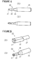
- As shown in Fig. 1, the diamond tool is equipped with a
tip 13 of composite materials which contains alayer 11 of hot-pressed diamond compact bonded to a supportingmember 12 of hard sintered alloy. - In case a drill is manufactured from the
tip 13 of composite materials, thetip 13 must be connected by any means to the top end of ashank 15 as shown in Fig. 2. However, the top end of the drilling tool is generally smaller in diameter than lmm, and in some cases, smaller than 0.5mm. If thetip 13 is not very rigidly bonded to theshank 15 of a small diameter, thetip 13 tends to be easily removed at thebonded portion 16 from theshank 15 during the working of thetip 13 into drill. Particularly, the hot-pressed diamond compact exhibits a high resistance to working. Then, the bonding strength obtained by silver brazing is insufficient for maintaining the tip to the shank in such working. Thus it has been difficult to manufacture a high performance drill therefrom. - There is an electron beam welding as a means for providing a high strength bonding. But as the electron beam welding is very complicated and expensive to conduct, it has not been able to satisfy the increasing demand for high performance drills.
- A rigid bonding has not been obtained also by hot pressing the head member together with the supporting member. The blank for the microdrill must be of a small section and elongated form. It was practically impossible to hot press such an elongated member by the prior art technique.
- Namely, if a compact of powder material in a form of a long stick is hot pressed by pressing the same in its axial direction, a rigid hot-pressed compact cannot be obtained since the powder material is not pressed sufficiently at the mid portion in the axial direction due to a considerable pressure loss by the thick layer of the powder material. Further, if the pressing pressure is enhanced in the axial direction of the stick, the pressure becomes distributed so irregularly in the hot-press container that the stick tends to be buckled or curved. Thus, a hot-pressed compact cannot be obtained with precision.
- In view of the above mentioned problem, in the case of the hot press of an elongated piece, it can be conceived that the compact material is charged in the container in such a disposition that the axial direction of the piece is perpendicular to the pressing direction. If an elongated composite compact in which two layers of materials are arranged in their axial direction is hot pressed in such a disposition, a sufficient bonding strength cannot be obtained between these layers since the pressure is not sufficiently exerted at the interface of these layers in the direction perpendicular thereto.
- As to the supporting member or base member of the composite stick, it must be of a high strength, particularly in the case of a microdrill. As mentioned above, the integration density of the circuit board has become higher in these years, and this tendency will be enhanced. That is, the diameter of the machined hole in the circuit board will become smaller. Thus, microdrills of which the diameter is, for example, 0.1mm or 0.3mm will be demanded. Then, it should be noted that as the microdrill becomes smaller in diameter, it tends to be broken or bent easier. If the drill is bent before the duration of life of the diamond member, it is meaningless to use the expensive diamond.
- To the contrary, if the supporting member is made of a soft or low rigidity material, it tends easily, to be buckled so that a straight hole cannot be machined. Moreover, the supporting member of a soft material would wear out easily due to the abrasion by cuttings.
- The object of the present invention is to resolve the above explained problems of the prior art, and more particularly it is a main of object of the present invention to provide a stick of composite materials having a super hard hot-pressed head member bonded rigidly to the supporting member, and the process for preparation of the )same.
- Another object of the present invention is to produce, readily and at low cost, microdrills having an excellent wearing resistance and a high rigidity.
- A further object of the present invention is to provide >at low cost a high performance microdrill of a long duration of life, which is suitably employed in machining circuit boards of low machinability such as the glass-epoxy circuit board.
- A still further object of the present invention is to provide an elongated stick of composite materials and the process for preparation thereof, which is suitably usable as a punch or head member of the dot character printer.
- Brief Description of the Accompanying Drawings
- Fig. 1 a persepective view of a hot-pressed diamond composite compact of the prior art;
- Fig. 2 is a perspective view of a drill containing the hot pressed diamond compact composite material at it top end portion;
- Figs. 3 (a) to (d) each shows the embodiments of the stick of composite materials according to the present invention;
- Fig. 4 (a) shows diagramatically how a microdrill is prepared from the cylindrical stick of the present invention, and Fig. 4 (b) shows the thus obtained microdrill;
- Fig. 5 (a) shows diagramatically how a punch is prepared from the stick of the present invention which has a square section, and Fig. 5 (b) shows the thus obtained punch;
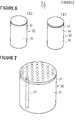
- Fig. 6 (a) is a persepective view of an example of the composite material block prepared according to the present invention, and Fig. 6 (b) shows another example of the composite material block which has an interlayer;
- Fig. 7 shows the position at which a stick of composite materials is to be cut out from the composite material block according to the present invention;
- Fig. 8 (a) is a persepectiv view of an electrode means comprising three pipe electrodes for cutting three sticks from the composite material block simultaneously, and Fig. 8 (b) is a detailed view of the pipe electrode shown in Fig. 8 (a); and
- Fig. 9 (a) is a side view of an electrode means comprising a plurality of pipe electrodes, and Fig. 9 (b) is a plan view of the same electrode means showing the positions of the electrodes with respect to the composite material block.
- The present inventors have succeeded in obtaining a stick of composite materials having a super-hard head member by hot pressing a composite compact of a large section with respect
to its axial length and cutting the thus hot-pressed composite material block into a plurality of pieces in the form of an elongated stick by means of the electron spark, electon beam, laser beam, ion beam cutting methods, etc. - First, the characteristics of the shape and the size of the stick of composite materials according to the present invention will be explained with reference to Figs. 3 (a) to (d).
- Figs. 3 (a) to (d) illustrate respectively an embodiment of the stick of composite materials according to the present invention.
- The
stick 23 of composite materials shown in Fig. 3 (a) is generally of a cylindrical form and comprises a super-hard hot-pressedhead member 21 and a supportingmember 22 bonded at one end thereof to thehead member 21. - On the other hand, in the
stick 23 shown in Fig. 3 (b), thehead member 21 is bonded to one end of the supportingmember 22 through aninterlayer 24. - The
sticks 23 shown in Figs. 3 (c) and (d) have a square section. In the stick shown in Fig. 3 (c), thehead member 21 is directly bonded to the supportingmember 22, while, in Fig. 3 (d), the head member is bonded through aninterlayer 24 to the supportingmember 22. - However, the sectional shape of the stick of composite materials according to the present invention is not restricted only to circular or square form, and it may be of any other sectional form.
- According to the present invention, the sectional diameter or the sectional equivalent diameter of the stick of composite materials must not be larger than 3mm. A stick of composite materials having a diameter or an equivalent diameter larger than 3mm is not appropriate as a blank of the microdrill. If such a stick of a large diameter is used as a blank of the microdrill, the chipping margin which is to be removed in forming cutting edges becomes uneconomically large. Moreover, a composite material compact large than 3mm in diameter can be prepared by other process than the present invention.
- The super-hard hot-pressed head member of the stick must be of 0.3 to 2mm in length according to the present invention. With a head member shorter than 0.3mm in length, it is not possible to improve substantially the cutting performance of the drill. On the other hand, the use of a stick having a super-hard head member longer than 2mm consumes a relatively large amount of an expensive material such as a diamond powder and thus it is uneconomical.
- Further, the supporting
member 22 must be more than five times longer in the axial direction of the stick than thehead member 21, because the supportingmember 22 is to be inserted in a hole disposed at the top end of the shank of a drill and a sufficiently long cutting edges is to be worked on its circumferential surface. - Next, the use of the stick of composite materials according to the present invention will be explained with reference to Figs. 4 and 5.
- As shown in Fig. 4 (a), a
shank 25 for the drill is drilled at its top end to define ahole 26 having a substantially same diameter as thecylindrical stick 23. Thecylindrical stick 23 is fitted into thehole 26 at its end portion and fixed therein. For fixing thestick 23 in thehole 26, a brazing material is poured in thehole 26 beforehand and then the end of thestick 23 is brazed to theshank 25. Then, the circumferential surface of thestick 23 is ground to remove the surface layer in a depth of about 0.1mm and the grooves and the cutting edges are formed to provide a microdrill as shown in Fig. 4 (b). - Figs. 5 (a) and (b) illustrate an example of use of the square stick of the present invention.
- The end portion remote from the
head member 21 of the suppportingmember 22 is worked by grinding into acylindrical form 27 over a certain length as shown in Fig. 5 (a). The thus formed cylindrical end portion of the supportingmember 22 is fitted into ahole 26 disposed at the top end of theshank 25, and brazed thereat. Then, the circumferential surface of the square stick -23 is subjected to a finish working to a predetermined shape to provide a square punch as shown in Fig. 5 (b). - The cylindrical stick of composite materials according to the present invention does not require the complicated electron beam welding and has a strong and rigid integrated structure. Thus, it is possible to machine holes at high efficiency in a high performance circuit board such as a glass-epoxy circuit board.
- Further, it is easy to fit the end portion of the cylindrical stick of composite materials of the present invention into a hole of the shank. Such an attachment does not require any special working of the cylindrical stick. Moreover, forming of the cutting edges is also easy and the amount of cuttings generated in such a working is small.
- According to the present invention, there is further provided a process for preparing a stick of composite materials comprising a hot-pressed super-hard head member containing higher than 50 vol% of a diamond powder and/or a high pressure boron nitride powder, and a supporting member being bonded at one of its ends with said hot-pressed super-hard head member, said process comprising the steps of:
- charging a hot press container with two layers of materials by piling them adjacent to each other in the pressing direction, one of said layers being for preparing the hot-pressed super-hard head member and, the other layer being for preparing said supporting member which is to be bonded with the first-mentioned layer during the hot-pressing;
- hot pressing said layers of materials under a high pressure and at a high temperature to sinter the first-mentioned layer, to thereby provide a composite material block having a hot-pressed super-hard layer of which thickness is not larger than 1/6 of that of the composite material block;
- cutting the composite material block in its axial direction by means of one method selected from the group consisting of electron spark, electron beam, laser beam and ion beam cutting methods into at least two sticks of composite materials each having a diameter not larger than 3 mm.
- The composite material block may be of any sectional shape. But, the length in the axial direction, that is, in the pressing direction, must not be larger than three times, preferably two times of the equivalent diameter thereof. If the axial length is longer than three times of the equivalent diameter of the section perpendicular to the axis, the pressure exerted to the block during the hot press tends to distribute irregularly to thereby cause the buckling or curving of the block.
- In this specification, the "equivalent diameter" of a section denotes the diameter of a circle of which surface is equal to the section in problem.
- The diamond powder and/or high pressure boron nitride powder have preferably a mean particle size not greater than 30)lm to endow a high wearing resistance and a high rigidity to the resulting stick of composite materials.
- However, with a diamond powder and/or high pressure boron nitride powder having a mean particle size larger than 10 µm, the cutting tool, drill and punch are not finish worked so sharply that a high performance is not attained. Thus, it is further preferable to use a diamond powder and/or high pressure boron nitride of a mean particle size not greater than 10µm.
- The layer containing a diamond powder includes, for example, only a diamond powder, or a mixture containing more than 70 vol% of a diamond powder and the balance being a binder powder of which predominant constituent is Fe, Co or Ni. As a preferred example of such a mixture for the first layer, there is a mixture containing not lower than 70 vol% of a diamond powder and a powder of WC- 5 to 15 vol% Co.
- When the first layer for the head member contains only a diamond powder, the binding material contained in the second layer permeates in the first layer during the hot pressing of the first layer, whereby attaining the sintering of the first layer.
- The first layer, which contains a high pressure boron nitride, may contain only the boron nitride powder or may contain not lower than 50 vol% of a high pressure boron nitride and, as a binder, a carbide, nitride and carbonitride of the Group IVa, Va, VIa elements of the Periodic Table, and Al and/or Si. Here, the high pressure )boron nitride includes the boron nitrides of wurtzite structure and cubic structure.
- The high pressure boron nitride powder can be hot pressed without binder to a hard compact body.
- The second layer for preparing the supporting member may be a so-called hard sintered alloy, a cerment or powder material therefor. The hard sintered alloy contains at least one member selected from the group consisting of carbides, nitrides, carbonitrides, borides, silicates and mutual solid solutions thereof of the Group IVa, Va, VIa elements of the Periodic Table, and a binder of iron metal such as Fe, Co and Ni. A cermet includes (Mo, W) C binded with an iron metal such as Ni or Co.
- As another type of the second layer, there is the so-called "heavy metal" or its powder material, which contains 80 to 98 wt% of W and the balance being Ni-Fe or Ni-Fe-Cu.
- As explained in the above, the second layer may be a sintered alloy or it powder material. In view of the convenience in handling the same and of the fact that a high pressure is easily applied during the hot press process, it is preferable to use a sintered alloy in the form of a solid block.
- According to a preferred embodiment of the invention, a hard sintered alloy containing WC as the predominant constituent is used as the second layer. Such a hard sintered alloy presents a high rigidity together with an excellent wearing resistance while maintaining a high strength.
- TiC and TaC, which are usually contained in the hard sintered alloy for use as a tool for ;cutting steel materials, are not effective to improve the wearing resistance and tend to rather lower the strength of the alloy. But, the hard sintered alloy contains as low as several percentage of TaC, Cr3C2 and VC, which are effective for restraining the grain growth of WC or for refining the grains of the alloy. Further, as a binder, Co and Ni are preferably used, and Co is the most preferable binder.
- The present inventors further conducted experiments and examination in order to improve the bending strength and the wearing resistance of the support member.
- As mentioned in the above, the length of the supporting member must be more than five times larger than that of the head member. Thus, there is a reasonable possibility that the stick would be bent or buckled at the supporting member. The severe abrasion of the supporting member due to a high rotation of the drill must be also taken into account.
- In order to resolve these problems, it should be firstly noted that one of the characteristics of the present invention resides in that the bonding between the head member and the supporting member is made during the hot press process of the head member. Then, the supporting member undergoes a high temperature and an ultra high pressure where the diamond or high pressure boron nitride is stable. That is, a sintering of WC-Co is conducted under vacuum at a temperature of 1300 to l500oC, while the hot press of the diamond or high pressure boron nitride is conducted around the same temperature range but under an ultra high pressure of 40,000 to 50,000 atm. Accordingly, the ultra high pressure affects the mechanical properties of WC-Co, regardless of whether the second layer is in the sintered form or powdered form.
- Since it is easy and convenient to use the second layer in the form of the sintered solid block, the present inventors have conducted various experiments by hot pressing WC-Co sintered alloy under the above condition, and found the following phenomena.
- Generally, the mechanical properties of WC-Co sintered alloy depend upon the content of Co and the particle size of WC crystals. But, if WC crystals having a particle size larger than 3y. m are exposed to a high temperature and an ultra high pressure, the WC crystals are broken to vary the mechanical properties drastically. Thus, the mean particle size of WC in the sintered alloy used as the second layer should be smaller than 3µm.
- However, according to the experiments of the present inventors, the mechanical properties of WC-Co alloy are not always degraded after the exposition thereof to the hot pressing condition of the diamond or the high pressure boron nitride. This is due to the fact that, since WC crystals have a high wettability with the liquid Co under the hot press condition, the liquid Co permeates into the broken WC crystals to thereby bond the same solidly.
- According to the technical knowledge of the prior art, if the WC-Co alloy having a mean particle size smaller than 1µm is contaminated with a small amount of large particles of WC crystals, such large particles tend to develop a fracture therefrom. Thus such large WC particles were believed to lower the strength of the alloy. In the experiments of the present inventors, however, there were found some examples where the strength is heightened even after undergoing the hot press. Such increase in the strength depends upon the content of the binder metal in the sintered alloy. The present inventors consider that the increase in the strength is due to the phenomenon that the binder metal permeates into the large broken WC particles and bond the same solidly.
- On the other hand, there would not raise any problem if the pressing of the ultra high pressure is effected in a perfectly hydrostatic manner. But, such a perfect condition is scarcely attained in the practical production while efforts are made to approach the production to it. Thus, the hard sintered alloy undergoes some irregular deformation during the hot press process. In the case of WC-Co alloy containing a sufficient amount of Co, the deformation of the crystal structure may be compensated by the permeation of Co to the deformed sites. But, in WC-Co alloy of a low Co content, the portion which is deformed most severely would cause defects such as fine fissures or holes.
- After determining the bending strength of WC-Co alloy by varying the Co content, the present inventors found that with a Co content lower than 7 wt%, the bending strength lowers after the hot press of the high temperature and ultra high pressure, while the bending strength increases when the alloy contains more than 12 wt% of Co.
- It is considered that, in the case of the Co content lower than 7 wt%, the broken WC crystals are not permeated with Co and causes the defects as explained in the above. On the other hand, in the case of the Co content higher than 12 wt%, the bending strength is heightened due to the following phenomenon:
- First, it is believed that the fracture of WC-Co alloy develops from the coarse WC crystals, holes or vacancies, and abnormal phases. In the experiments, it has been confirmed by microscopic observation before the hot pressing that there did not exist abnormal phase in the alloy. The coarse WC crystals affects the strength as explained in the above.
- The "holes" designates the holes ranging from several ikm to several hundred µm. From the experience in the HIP process, it is supposed that such holes collapse due to the ultra high pressure or are filled with Co. Since the hot press is conducted at about the same temperature as the HIP but under a pressure higher by ten times than the HIP, such a phenomenon would be further intensified in the hot press according to the present invention.
- In the WC-Co alloy of 20 wt% Co, the bending strength was increased by 30% after the hot press. The reason for this increase in the strength will be further examined in more detail.
- The Co phase in the WC-Co alloy is of FCC structure and is composed of almost pure Co, while it contains around 10 wt% of W when the C content is low. Then, in general, the WC-Co alloy of a high Co content is easily deformed.
- The strain-stress curve of such a high Co content WC-Co alloy is of low gradient, which means a low bending strength.
- After an examination of the Co phase of the alloy which has been subjected to the hot press, it was found that the Co phase contains about 15 wt% of W and becomes hard to deform. Such an increase in the W content in the Co phase will be analysed as follows:
- First, the Co phase deposited at the eutectic temperature from the ternary eutectic crystal of Co-W-C contains about 20 wt% of W. During the cooling step after the usual sintering, W is deposited in the W phase from the ternary eutectic Co-W-C. But, in the hot press of the process according to the present invention, when the 'hot press is completed, the electric supply for heating means is cut off to cool the hot-pressed compact and then the pressing pressure is loosed. It means that when the compact is cooled to the eutectic temperature at which W would deposit in the WC phase, the compact is still subjected to an ultra high pressure. Under such an ultra high pressure, the diffusion velosity of W is lowered in the solid phase and thus the deposition of W to the WC phase is prevented. Such assumption is confirmed by the fact that much of W is present in the state of solution in the Co phase of the WC-Co alloy of the support member of the stick of the present invention. Accordingly, the WC-Co alloy containing a high amount of Co which is considered to be too deformable under the usual condition exhibits a higher bending strength after the hot press of high temperature and ultra high pressure.
- Then, according to a preferred embodiment of the present invention, the supporting member is composed of a hard sintered alloy of which the mean particle size of the carbide is smaller than 2µm and which contains more than 12 wt% of a binder metal.
- One of the important characteristis of the stick of composite materials according to the present invention resides in that the bonding between the hot-pressed super-hard head member and the supporting member is made during the hot press of the head member. Accordingly, it is necessary to select the materials of the first and second layers so that these layers are bonded to each other by the hot press of the first layer. The bonding of the layers is easily attained because the binding agent of the iron group metal permeates from the second layer to the first layer at the high temperature and under the ultra high pressure. Thus, it is easy for those skilled in the art to determine the chemical compositions of the first and second layers in the above described ranges so as to bringing out the bonding of these layers.
- Further, the powder of high pressure boron nitride can be sintered without any binding agent, and then it can be bonded to the support member during the sintering thereof.
- According to an embodiment of the present invention, an interlayer having a thickness less than 0.5mm is disposed between the first and second layers and these layers are hot pressed together.
- A preferable interlayer contains less than 70 vol% of high pressure boron nitride and the balance composed mainly of at least one selected from the group consisting of carbides, nitrides, carbonitrides and borides of the Group IVa element such as Ti, Zr and Hf and their mutual solid solutions, and more than 0.1 wt% of Al and/or Si.
- According to a preferred embodiment, the second layer for the support member comprises at least two layers of >materials arranged adjacent to each other in the axial direction thereof. The second layer may be composed of, for example, a layer of WC-Co at the side remote from the head member, and a layer of a cermet of (Mo, W) C bonded by Ni or Co at the adjacent side to the head member.
- Further, two layers of materials each intended for the head member are arranged respectively as the first layer at the upper and lower sides of the second layer and are hot pressed to provide a composite block which contains the first layers at the both sides. The composite block is then cut into at least two sticks each having the super-hard head members at the both ends.
- Now, the cutting method of the composite sticks from the composite material block will be explained with reference to the drawings.
- There are two types of the composite material block. In one type, the
composite material block 33 comprises athin layer 31 of hot-pressed diamond compact and a supportinglayer 32 of hard sintered alloy bonded to thethin layer 31 at the top surface thereof as shown in Fig. 6 (a). In the other type, thelayer 31 is bonded to the supportinglayer 32 through aninterlayer 34 as shown in Fig. 6 (b). Although the composite material blocks shown in Figs. 6 (a) and (b) are of the cylindrical form, it may be of any other form such as a square timber. - As shown in Fig. 7, the
composite material block 33 is cut in its axial direction into a plurality of sticks each having a diameter or an equivalent diameter not greater than 3mm by means of, for example, the electron spark cutting method employing wire or pipe electrode, or by a beam of a high convergency and a high energy such as electron beam, laser beam and iron beam. - In the electron spark wire cutting method, high electric pressure is applied between a tension wire and the composite material block, and the block is cut off by the running tension wire. This method is described in detail in US Patent No. 3,103,137 and thus it will not explained here.
- In the electron spark cutting method employing the pipe electrodes, high electric pressure is applied between the electrodes and the portions of the composite material block to be cut off, while these are separated at a certain distance, or these are dipped in an insulating liquid.
- Figs. 8 (a) and (b) show an example of a electrode means which is employed in the process of the present invention. The electrode means comprises a
support plate 40 and threepipe electrodes support plate 40 so as to cut off three composite sticks simultaneously. Thepipe electrode 41 is, as shown in Fig. 3 (a), of a hollow cylindrical form and is disposed with ahole 42 for liberating the gasified material which is generated at the time of cutting. - Fig. 9 (a) shows another type of the electrode means which comprises a plurality of
pipe electrodes 41. Fig. 9 (b) shows the disposition of thepipe electrodes 41 with respect to the upper surface of the composite material block. - ' The electrode means which may be employed in the process according to the present invention is not restricted to the types described in the above, and it may be of any other type with which the composite block can be cut off into a plurality of sticks, such as an electrode of a honeycomb form.
- Since the electron spark cutting method is by itself well-known in the art and is not the direct subject matter of the present invention, it will not be explained here any more.
- The composite material block can be cut into stick members of any sectional configuration by means of a beam of a high convergency and a high energy such as electron beam, laser beam and ion beam. These high energy beam cutting methods are also well-known by itself in the art and are not 'the direct subject matter of the present invention, these will not be explained in more detail here.
- The stick of composite materials of the present invention has been explained and defined by the chemical composition thereof before the hot press, but it is not explained as hot-pressed. However, the chemical composition and microscopic structure of the components of the composite stick, that is, of the head member, supporting member and interlayer, vary delicately depending upon the temperature, pressing pressure and time duration of the hot press. Thus, the present invention will be more clearly and definitely understood if it is defined in terms of the chemical composition of the starting materials.
- The present invention will be explained by way of examples which illustrate the preferred examples of the present invention but are not to be construed to restrict the scope of the invention.
- By the way, the percentage indicates percentage by volume in this specification unless otherwise indicated.
- The followings were prepared:
- A ring of WC-12%Co sintered alloy of 18mm in outer diameter, 14mm in inner diameter and 15mm in height;
- a cylinder block of WC-12%Co sintered alloy of 14mm in outer diameter and 12mm in height;
- a circular disc of WC-12%Co sintered alloy of 14mm in outer diameter and 0.5mm in thickness; and
- a mixture of diamond powder containing 85% of diamond powder having a particle size of 0.5,Am and the balance being WC-15%Co powder having a particle size smaller than 0.5µm.
- The cylinder block was inserted in the ring to define therein a hollow space of 14mm in diameter and 3mm in depth in which the mixture of diamond powder was then charged and pressed to form a layer of 1.5mm in thickness, and the upper portion of the hollow space was closed with the circular disc to form a container. The thus prepared container was charged in a hot press machine and the hot press was conducted at 1370°C, under a pressure of 55 kb and for 15 minutes.
- After cooling the container and loosing the pressing pressure, the circur disc was removed by grinding to obtain a composite block composed of a supporting layer of 12mm in height, a hot pressed diamond layer of lmm in thickness bonded to the upper surface of the supporting layer and a ring of sintered alloy surrounding the circumference of the head layer and the supporting layer.
- The composite material block was subjected to the electron spark wire cutting method as shown in Fig.' 7 to obtain cylindrical sticks of composite materials of lmm in diameter and 13mm in length each of which contains a hot-pressed diamond head member of lmm in length bonded at the top end of the supporting member of WC-12%Co.
- The above composite block was also cut by the electron spark method employing a electrode means shown in Fig. 9 (a) to obtain sticks of composite materials of the same configuration as the above mentioned composite sticks.
- One of the above composite stick was fitted in a hole of a steel shank as shown in Fig. 4 (a) and brazed thereto. The outer surface of the stick was then removed by grinding in a depth of O.lmm and worked to form grooves and blades edges.
- With the thus obtained micro drill, it was possible to conduct hole machining of more than 200,000 shots in glass-epoxy circuit boards.
- The followings were prepared:
- A ring of WC-12%Co sintered alloy of 18mm in outer diameter, 14mm in inner diameter and 20mm in height;
- a cylinder block of WC-12%Co sintered alloy of 14mm in outer diameter and 18mm in height;
- a circular disc of WC-12%Co sintered alloy of 14mm in outer diameter and 0.5mm in thickness;
- a mixture of diamond powder containing 90% of diamond powder having a particle size of 3,µm and the balance being Co powder; and
- another mixture of boron nitride powder containing 60% of high pressure boron nitride (which will be abbreviated as "CBN" hereinafter) having a particle size of 3pm and the balance being a powder of TiN-10wt%Al.
- A solution of the mixture of CBN powder was applied with a thickness of 50µm on the top surface of the cylinder block and heated to remove the solvent.
- The cylinder block was then inserted in the ring to define therein a hollow space in which the mixture of diamond powder was charged and pressed to form a layer of 1.8mm in thickness, and the upper portion of the hollow space was closed with the circular disc to form a container. The thus prepared container was charged in a hot press machine and the hot press was conducted at 1400°C, under a pressure of 55 kb and for 10 minutes.
- After cooling the container and loosing the pressing pressure, the circur disc was removed by grinding to obtain a composite block composed of a supporting layer of 18mm in height, a hot pressed diamond layer of 1.2mm in thickness bonded to the upper surface of the supporting layer through an interlayer of hot pressed CBN of a thickness of 25ym and a ring of sintered alloy surrounding the circumference of the head layer and the supporting layer.
- The composite material block was subjected to the electron spark wire cutting method to obtain cylindrical sticks of composite materials of 2mm in diameter and 19.2mm in length each of which contains a hot pressed diamond head member of 1.2mm in length bonded at the top end of the supporting member of WC-12%Co through the interlayer of hot pressed CBN of 25µm in thickness.
- The above composite block was also cut by the electron spark method employing a pipe electrode means to obtain sticks of composite materials of the same configuration as the above mentioned composite sticks.
- One of the above composite stick was fitted in a hole of a steel shank and brazed thereto. The outer surface of the stick was then finish worked by grinding to form a punch of a predetermined size.
- The obtained punch exhibited a service life time 100 times longer than the steel punch of the prior art in punching paper-bakelite circuit boards
- A composite material block was prepared by conducting a hot press in the same manner as Example 2 except that a cylinder block of WC-l%Cr3C2-20%Co was employed in lieu of that of :WC-12%Co and that the mixture of diamond powder was charged in the container so as to obtain a hot pressed layer of lmm in thickness.
- The thus obtained composite block was subjected to the electron spark wire cutting method to obtain cylindrical composite sticks of 0.3mm in diameter and 18.5mm in length, each comprising a supporting member of WC-l%Cr3C2-20%Co having a mean particle size of 0.7µm and a head member of hot pressed diamond of 0.5mm in length bonded to the top end of the supporting member through an interlayer of hot pressed CBN of 25µm in thickness.
- The followings were prepared:
- A cylinder block of (Mo7, W3)C-11%Co sintered alloy of 24mm in outer diameter and 25mm in height and having a circular recessed portion of 20mm in diameter and 3mm in depth at the upper end thereof:
- a circular disc of WC-12%Co sintered alloy of 20mm in outer diameter and 0.5mm in thickness; and
- a mixture of diamond powder containing 80% of diamond powder having a particle size of 0.5µm and the balance being WC-15%Co powder having a particle size smaller than 0.5µm.
- The mixture of diamond powder was charged in the recessed portion and pressed to form a layer of the powder of 2.3mm in thickness and the recessed portion was closed with the circular disc to form a container. The thus prepared container was charged in a hot press machine and the hot press was conducted at 1400°C, under a pressure of 55 kb and for 15 minutes.
- After cooling the container and loosing the pressing pressure, the circur disc was removed by grinding to obtain a composite block composed of a hot pressed diamond layer of 1.5mm in thickness in that recessed portion and a cylinder block of (Mo7, W3)C-ll%Co.
- The composite block was subjected to the electron spark wire cutting method to obtain cylindrical sticks of composite materials of 2mm in diameter and 23.5mm in length each of which contains a hot pressed diamond head member of 1.5mm in length bonded at the top end of the supporting member of (Mo7, W3)C-11%Co.
- The above composite block was also cut by the electron beam cutting method to obtain sticks of composite materials of the same configuration as the above mentioned composite sticks.
- The hot press of the composite material block and the cutting thereof into the cylindrical sticks were conducted in the same manner as Example 4 except that a cylinder block of WC-0.5%VC-13%Co was employed in lieu of that of (Mo7,W3)C-ll%Co.
- The obtained cylindrical stick was of 2mm in diameter and 23.5mm in length and comprised a supporting member of WC-0.5%VC-13%Co having a mean particle size of 0.7µm, and a head member of hot pressed diamond of 1.5mm in length.
- The followings were prepared:
- A ring of WC-12%Co sintered alloy of 18mm in outer diameter, 14mm in inner diameter and 15mm in height;
- a cylinder block of 96wt%W-3wt%Ni-lwt%Cu alloy of 14mm in outer diameter and 12mm in height;
- a circular disc of WC-12%Co sintered alloy of 14mm in outer diameter and 0.5mm in thickness; and
- a mixture of CBN powder which was obtained by mixing a powder A containing 85% of CBN having a particle size of 3µm and the balance of TiN0.82 with a powder B of Al at a ratio of A:B of 80:20, heating the mixture in a vacuum furnace for 30 minutes at 1000°C and grinding the same to 0.3µm.
- The cylinder block of W alloy was inserted in the ring to define therein a hollow space of 14mm in diameter and 3mm in depth in which the mixture of CBN powder was then charged and pressed to form a layer of a thickness of 1.7mm, and the upper portion of the hollow space was closed with the circular disc to form a container. The thus prepared container was charged in a hot press machine and the hot press was conducted at 1250°C, under a pressure of 50 kb and for 20 minutes.
- After cooling the container and loosing the pressing pressure, the circur disc was removed by grinding to obtain a composite block composed of a supporting layer of 12mm in height, a hot pressed CBN layer of lmm in thickness bonded to the upper surface of the supporting layer and a ring of sintered alloy surrounding the circumference of the head layer and the supporting layer.
- The composite material block was subjected to the electron spark wire cutting method to obtain cylindrical sticks of composite materials of 1mm in diameter and 13mm in length each of which contains a hot pressed CBN head member of lmm in length bonded at the top end of the supporting member of 96wt%w-3wt%Ni-lwt%Cu alloy.
- The above composite block was also cut by the ion beam cutting method to obtain sticks of composite materials of the same configuration as the above mentioned composite sticks.
- The hot press was conducted in the same manner as Example 6 except that a cylinder block of WC-2%TaC-16%Co was employed in lieu of that of W alloy.of W-3wt%Ni-lwt%Cu to obtain a composite material block comprising a supporting layer of 12mm in height, a layer of hot pressed CBN of lmm in height bonded on the upper surface of the supporting layer, and a ring of the sintered alloy surrounding the supporting layer and the CBN layer.
- The thus obtained composite block was subjected to the electron spark wire cutting method to obtain square sticks of lmm in sectional side and 13mm in length.
- Each square stick comprised a supporting member of WC-2%TaC-16%Co having a mean particle size of 1µm and a head member of lmm in length of hot pressed CBN bonded to the top end of the supporting member.
- The square stick was ground at one end portion of the sintered alloy side for a certain length to a cylindrical form as shown in Fig. 5 (a). Then, the cylindrical end portion was fitted in a hole of a steel shank and brazed thereto. The square stick was then finish worked to obtain a square punch of a predetermined size. It was confirmed that the thus obtained square punch has an excellently long service life time as compared with the steel square punch of the prior art in punching the paper-bakelite circuit boards.
- The followings were prepared:
- A ring of WC-12%Co sintered alloy of 40mm in outer diameter, 36mm in inner diameter and 40mm in height;
- a cylinder block of WC-12%Co sintered alloy of 36mm in outer diameter and 34mm in height;
- a circular disc of WC-12%Co sintered alloy of 36mm in outer diameter and 0.5mm in thickness; and
- a mixture of CBN powder containing 60% of CBN powder having a particle size of 3ylm and the balance being TiN-10%wt%Al powder.
- The mixture of CBN powder was compacted to a form of a circular disc of 36mm in diameter and 2.5mm in thickness.
- Inside the ring, a circular disc of sintered alloy, a circular disc of CBN compact, a cylinder block of sintered alloy, another circular disc of CBN compact and another circular disc of sintered alloy were piled in the above mentioned order from the bottom side to thereby form a container. The thus prepared container was charged in a hot press machine and the hot press was conducted at 1200°C, under a pressure of 40 kb and for 20 minutes.
- After cooling the container and loosing the pressing pressure, the circur discs of sintered alloy of the upper and lower sides were removed by grinding to obtain a composite block of 36mm in diameter and composed of a supporting layer of 34mm in height, two hot pressed CBN layers each being of 1.5mm in thickness and respectively bonded to the upper and lower surfaces of the supporting layer and a ring of sintered alloy surrounding the circumference of the CBN layers and the supporting layer.
- The composite material block was subjected to the electron spark wire cutting method to obtain cylindrical sticks of composite materials of 2.5mm in diameter and 37mm in length each of which contains a hot-pressed CBN head member of 1.5mm in length bonded at the both ends of the supporting member of WC-12%Co.
- The above composite block was also cut by the electron beam cutting method to obtain sticks of composite materials of the same configuration as the above mentioned composite sticks.
- Each of these sticks was cut into two pieces at the mid position of the axial direction to provide a pair of cylindrical sticks, each being of 2.5mm in diameter and 18mm in length and containing a CBN head member of 1.5mm in length bonded to one end of a supporting member of WC-12%Co.
Claims (21)
Priority Applications (1)
| Application Number | Priority Date | Filing Date | Title |
|---|---|---|---|
| AT85304135T ATE49147T1 (en) | 1984-06-12 | 1985-06-11 | ROD MADE OF COMPOSITE MATERIALS AND METHOD FOR ITS MANUFACTURE. |
Applications Claiming Priority (8)
| Application Number | Priority Date | Filing Date | Title |
|---|---|---|---|
| JP120219/84 | 1984-06-12 | ||
| JP59120219A JPH0742488B2 (en) | 1984-06-12 | 1984-06-12 | Method for manufacturing rod-shaped body of composite sintered material |
| JP59120218A JPS60264371A (en) | 1984-06-12 | 1984-06-12 | Composite sintering material cylindrical body |
| JP120218/84 | 1984-06-12 | ||
| JP163095/84 | 1984-08-02 | ||
| JP59163095A JPH0742489B2 (en) | 1984-08-02 | 1984-08-02 | Abrasion resistant parts with tool or hard head made of composite sintered material |
| JP49559/85 | 1985-03-13 | ||
| JP60049559A JPS61209821A (en) | 1985-03-13 | 1985-03-13 | Method of manufacturing bar type body of composite sintered material |
Publications (3)
| Publication Number | Publication Date |
|---|---|
| EP0168953A1 true EP0168953A1 (en) | 1986-01-22 |
| EP0168953B1 EP0168953B1 (en) | 1990-01-03 |
| EP0168953B2 EP0168953B2 (en) | 1998-07-01 |
Family
ID=27462375
Family Applications (1)
| Application Number | Title | Priority Date | Filing Date |
|---|---|---|---|
| EP85304135A Expired - Lifetime EP0168953B2 (en) | 1984-06-12 | 1985-06-11 | Stick of composite materials and process for preparation thereof |
Country Status (5)
| Country | Link |
|---|---|
| US (1) | US4880707A (en) |
| EP (1) | EP0168953B2 (en) |
| KR (1) | KR920001585B1 (en) |
| CA (1) | CA1286510C (en) |
| DE (1) | DE3575092D1 (en) |
Cited By (11)
| Publication number | Priority date | Publication date | Assignee | Title |
|---|---|---|---|---|
| EP0206652A2 (en) * | 1985-06-13 | 1986-12-30 | De Beers Industrial Diamond Division (Proprietary) Limited | A method of making a blank of a drill bit |
| WO1987001634A1 (en) * | 1985-09-16 | 1987-03-26 | Johann Steiner | Process and device for pressure-sintering for the production of metal-embedded diamond tools |
| EP0223474A2 (en) * | 1985-11-04 | 1987-05-27 | De Beers Industrial Diamond Division (Proprietary) Limited | Method of making a drill blank |
| EP0295946A1 (en) * | 1987-06-18 | 1988-12-21 | Manxtal Cutting Tools Limited | Drill bit with cutting insert |
| EP0417302A1 (en) * | 1989-02-22 | 1991-03-20 | Sumitomo Electric Industries, Ltd. | Nitrogen-containing cermet |
| DE4241140A1 (en) * | 1992-12-07 | 1994-06-09 | Krupp Widia Gmbh | Chip cutting tool with cutting insert(s) - has swarf disposed face outside cutting insert with processed surface |
| WO1994023891A1 (en) * | 1993-04-22 | 1994-10-27 | Schipperges, Karl-Heinz | Process for producing cutting elements for boring or parting-off tools |
| GB2491956A (en) * | 2011-06-13 | 2012-12-19 | Element Six Ltd | Twist drill tip and a method of manufacture using a precursor construction |
| US8794879B2 (en) | 2009-06-16 | 2014-08-05 | Komet Group Gmbh | Tool for machining workpieces |
| CN109996632A (en) * | 2016-11-15 | 2019-07-09 | 住友电工硬质合金株式会社 | Cutting element |
| EP3984698A1 (en) * | 2020-10-15 | 2022-04-20 | ETA SA Manufacture Horlogère Suisse | Cutting tool |
Families Citing this family (28)
| Publication number | Priority date | Publication date | Assignee | Title |
|---|---|---|---|---|
| EP0520403B1 (en) * | 1991-06-25 | 1995-09-27 | Sumitomo Electric Industries, Ltd | Hard sintered compact for tools |
| GB2259263B (en) * | 1991-08-08 | 1995-11-22 | Habit Diamond Ltd | Wear resistant tools |
| US5273379A (en) * | 1992-01-23 | 1993-12-28 | Gn Tool Co., Ltd. | Blank material for drill and drill therefrom |
| JPH06198504A (en) * | 1993-01-07 | 1994-07-19 | Sumitomo Electric Ind Ltd | Cutting tool for high hardness sintered body |
| KR100502585B1 (en) * | 2002-07-08 | 2005-07-20 | 일진디스플레이(주) | Sintering body having high hardness for cutting cast iron and The producing method the same |
| CN100573806C (en) * | 2003-06-30 | 2009-12-23 | 皇家飞利浦电子股份有限公司 | Discharge lamp |
| CA2600396C (en) * | 2005-03-22 | 2014-09-02 | S. George Lesinski | Implanting a therapeutic appliance into the cochlea |
| US20080166194A1 (en) * | 2007-01-09 | 2008-07-10 | Durfee Laverne R | Drill bit |
| US20100003094A1 (en) * | 2007-01-09 | 2010-01-07 | Irwin Industrial Tool Company | Drill bit |
| US8070397B2 (en) * | 2008-02-19 | 2011-12-06 | Irwin Industrial Tool Company | Self feed bit |
| KR100928387B1 (en) * | 2008-07-08 | 2009-11-23 | 베스너 주식회사 | Micro-drill and manufacturing method thereof |
| US20100307640A1 (en) * | 2009-06-03 | 2010-12-09 | Durfee La Verne R | Cutting edge and cutting tool |
| ITBO20100069A1 (en) * | 2010-02-09 | 2011-08-10 | Cruing Italy S R L | DRILLING TIP |
| GB201002375D0 (en) * | 2010-02-12 | 2010-03-31 | Element Six Production Pty Ltd | A superhard tip, method for making same and tool comprising same |
| KR20110094660A (en) * | 2010-02-17 | 2011-08-24 | 전주대학교 산학협력단 | Butt connection structure and the method |
| EP2502710B1 (en) | 2011-03-22 | 2020-04-22 | Black & Decker Inc. | Chisels |
| US9167362B2 (en) | 2012-09-13 | 2015-10-20 | Otokinetics Inc. | Implantable receptacle for a hearing aid component |
| US9333564B2 (en) | 2013-03-15 | 2016-05-10 | Black & Decker Inc. | Drill bit |
| USD737875S1 (en) | 2013-03-15 | 2015-09-01 | Black & Decker Inc. | Drill bit |
| WO2014141173A1 (en) * | 2013-03-15 | 2014-09-18 | Sandvik Intellectual Property Ab | Method of joining sintered parts of different sizes and shapes |
| USD734792S1 (en) | 2013-03-15 | 2015-07-21 | Black & Decker Inc. | Drill bit |
| DE102014207502B4 (en) * | 2014-04-17 | 2022-11-24 | Kennametal Inc. | rotary tool and tool head |
| JP2017047502A (en) * | 2015-09-02 | 2017-03-09 | 株式会社ディスコ | Cutting grind stone |
| DE102015013687A1 (en) * | 2015-10-21 | 2017-04-27 | Audi Ag | Method for producing at least one welding pin |
| US10702926B2 (en) | 2016-10-07 | 2020-07-07 | Sumitomo Electric Hardmetal Corp. | Rotary cutting blade material and method for manufacturing the same |
| CA3009032A1 (en) * | 2016-11-15 | 2018-05-24 | Sumitomo Electric Hardmetal Corp. | Cutting tool |
| JP7036437B2 (en) * | 2017-08-22 | 2022-03-15 | 住友電工ハードメタル株式会社 | Rotary cutting tools and their manufacturing methods |
| CN113586050B (en) * | 2021-07-06 | 2023-08-22 | 太原理工大学 | High-wear-resistance cutting pick containing diamond and preparation method thereof |
Citations (6)
| Publication number | Priority date | Publication date | Assignee | Title |
|---|---|---|---|---|
| GB540392A (en) * | 1940-04-30 | 1941-10-15 | Wheel Trueing Tool Co | Improvements in or relating to methods of making diamond tools |
| DE1602005A1 (en) * | 1966-12-06 | 1970-04-09 | Patra Patent Treuhand | Method for producing a fine bore |
| US3778180A (en) * | 1972-03-10 | 1973-12-11 | Federal Mogul Corp | Circuit board drill and method |
| FR2423626A1 (en) * | 1978-04-21 | 1979-11-16 | Christensen Inc | ROTARY DRILL BIT FOR DEEP DRILLS |
| GB2091763A (en) * | 1981-01-23 | 1982-08-04 | Sumitomo Electric Industries | Laminated sintered compositions including boron nitride |
| US4403015A (en) * | 1979-10-06 | 1983-09-06 | Sumitomo Electric Industries, Ltd. | Compound sintered compact for use in a tool and the method for producing the same |
Family Cites Families (7)
| Publication number | Priority date | Publication date | Assignee | Title |
|---|---|---|---|---|
| US3362802A (en) * | 1964-06-25 | 1968-01-09 | Chromalloy American Corp | Combination machining tool and tool support having improved vibration damping characteristics |
| AU512633B2 (en) * | 1976-12-21 | 1980-10-23 | Sumitomo Electric Industries, Ltd. | Sintered tool |
| US4235583A (en) * | 1978-03-23 | 1980-11-25 | General Motors Corporation | Extrusion die and method for making same |
| JPS5823353B2 (en) * | 1978-05-17 | 1983-05-14 | 住友電気工業株式会社 | Sintered body for cutting tools and its manufacturing method |
| AU529416B2 (en) * | 1978-07-04 | 1983-06-09 | Sumitomo Electric Industries, Ltd. | Diamond compact for a wire drawing die |
| CA1216158A (en) * | 1981-11-09 | 1987-01-06 | Akio Hara | Composite compact component and a process for the production of the same |
| CA1248519A (en) * | 1984-04-03 | 1989-01-10 | Tetsuo Nakai | Composite tool and a process for the production of the same |
-
1985
- 1985-06-11 CA CA000483612A patent/CA1286510C/en not_active Expired - Lifetime
- 1985-06-11 DE DE8585304135T patent/DE3575092D1/en not_active Expired - Lifetime
- 1985-06-11 KR KR1019850004091A patent/KR920001585B1/en not_active IP Right Cessation
- 1985-06-11 EP EP85304135A patent/EP0168953B2/en not_active Expired - Lifetime
-
1988
- 1988-08-10 US US07/231,644 patent/US4880707A/en not_active Expired - Lifetime
Patent Citations (6)
| Publication number | Priority date | Publication date | Assignee | Title |
|---|---|---|---|---|
| GB540392A (en) * | 1940-04-30 | 1941-10-15 | Wheel Trueing Tool Co | Improvements in or relating to methods of making diamond tools |
| DE1602005A1 (en) * | 1966-12-06 | 1970-04-09 | Patra Patent Treuhand | Method for producing a fine bore |
| US3778180A (en) * | 1972-03-10 | 1973-12-11 | Federal Mogul Corp | Circuit board drill and method |
| FR2423626A1 (en) * | 1978-04-21 | 1979-11-16 | Christensen Inc | ROTARY DRILL BIT FOR DEEP DRILLS |
| US4403015A (en) * | 1979-10-06 | 1983-09-06 | Sumitomo Electric Industries, Ltd. | Compound sintered compact for use in a tool and the method for producing the same |
| GB2091763A (en) * | 1981-01-23 | 1982-08-04 | Sumitomo Electric Industries | Laminated sintered compositions including boron nitride |
Cited By (17)
| Publication number | Priority date | Publication date | Assignee | Title |
|---|---|---|---|---|
| EP0206652A2 (en) * | 1985-06-13 | 1986-12-30 | De Beers Industrial Diamond Division (Proprietary) Limited | A method of making a blank of a drill bit |
| EP0206652A3 (en) * | 1985-06-13 | 1988-11-02 | De Beers Industrial Diamond Division (Proprietary) Limited | A method of making a blank of a drill bit |
| WO1987001634A1 (en) * | 1985-09-16 | 1987-03-26 | Johann Steiner | Process and device for pressure-sintering for the production of metal-embedded diamond tools |
| EP0223474A2 (en) * | 1985-11-04 | 1987-05-27 | De Beers Industrial Diamond Division (Proprietary) Limited | Method of making a drill blank |
| EP0223474A3 (en) * | 1985-11-04 | 1988-11-09 | De Beers Industrial Diamond Division (Proprietary) Limited | Drill blanks |
| EP0295946A1 (en) * | 1987-06-18 | 1988-12-21 | Manxtal Cutting Tools Limited | Drill bit with cutting insert |
| EP0417302A1 (en) * | 1989-02-22 | 1991-03-20 | Sumitomo Electric Industries, Ltd. | Nitrogen-containing cermet |
| EP0417302A4 (en) * | 1989-02-22 | 1991-07-24 | Sumitomo Electric Industries, Ltd. | Nitrogen-containing cermet |
| DE4241140A1 (en) * | 1992-12-07 | 1994-06-09 | Krupp Widia Gmbh | Chip cutting tool with cutting insert(s) - has swarf disposed face outside cutting insert with processed surface |
| WO1994023891A1 (en) * | 1993-04-22 | 1994-10-27 | Schipperges, Karl-Heinz | Process for producing cutting elements for boring or parting-off tools |
| US8794879B2 (en) | 2009-06-16 | 2014-08-05 | Komet Group Gmbh | Tool for machining workpieces |
| GB2491956A (en) * | 2011-06-13 | 2012-12-19 | Element Six Ltd | Twist drill tip and a method of manufacture using a precursor construction |
| GB2491956B (en) * | 2011-06-13 | 2015-08-12 | Element Six Ltd | Twist drill tips, precursor constructions for use in making same, and methods for making and using same |
| US9975185B2 (en) | 2011-06-13 | 2018-05-22 | Element Sux Abrasives S.A. | Twist drill tips, precursor constructions for use in making same, and methods for making and using same |
| CN109996632A (en) * | 2016-11-15 | 2019-07-09 | 住友电工硬质合金株式会社 | Cutting element |
| EP3984698A1 (en) * | 2020-10-15 | 2022-04-20 | ETA SA Manufacture Horlogère Suisse | Cutting tool |
| WO2022078641A1 (en) * | 2020-10-15 | 2022-04-21 | Eta Sa Manufacture Horlogère Suisse | Grinding tool |
Also Published As
| Publication number | Publication date |
|---|---|
| EP0168953B1 (en) | 1990-01-03 |
| KR860000113A (en) | 1986-01-25 |
| KR920001585B1 (en) | 1992-02-20 |
| US4880707A (en) | 1989-11-14 |
| CA1286510C (en) | 1991-07-23 |
| DE3575092D1 (en) | 1990-02-08 |
| EP0168953B2 (en) | 1998-07-01 |
Similar Documents
| Publication | Publication Date | Title |
|---|---|---|
| US4880707A (en) | Stick of composite materials and process for preparation thereof | |
| US4686080A (en) | Composite compact having a base of a hard-centered alloy in which the base is joined to a substrate through a joint layer and process for producing the same | |
| US6511265B1 (en) | Composite rotary tool and tool fabrication method | |
| EP0180243B1 (en) | Composite sintered material having sandwich structure | |
| US4604106A (en) | Composite polycrystalline diamond compact | |
| US4950557A (en) | Composite tool and a process for the production of the same | |
| US8147573B2 (en) | Bonding structure and bonding method for cemented carbide element and diamond element, cutting tip and cutting element for drilling tool, and drilling tool | |
| AU2001274230B2 (en) | Polycrystalline diamond with a surface depleted of catalyzing material | |
| KR980009199A (en) | Ceramic Bonded Cubic Boron Nitride Green Sheet | |
| JPS62142704A (en) | Composite sintered material | |
| JPH0525617B2 (en) | ||
| JPH0742488B2 (en) | Method for manufacturing rod-shaped body of composite sintered material | |
| JPS61152308A (en) | Small-sized twist drill made of hard sintered material | |
| JPH0798964B2 (en) | Cubic boron nitride cemented carbide composite sintered body | |
| JPH049754B2 (en) | ||
| JPS6141703A (en) | Composite sintered material |
Legal Events
| Date | Code | Title | Description |
|---|---|---|---|
| PUAI | Public reference made under article 153(3) epc to a published international application that has entered the european phase |
Free format text: ORIGINAL CODE: 0009012 |
|
| AK | Designated contracting states |
Designated state(s): AT BE CH DE FR GB IT LI NL |
|
| 17P | Request for examination filed |
Effective date: 19860501 |
|
| 17Q | First examination report despatched |
Effective date: 19870907 |
|
| GRAA | (expected) grant |
Free format text: ORIGINAL CODE: 0009210 |
|
| AK | Designated contracting states |
Kind code of ref document: B1 Designated state(s): AT BE CH DE FR GB IT LI NL |
|
| REF | Corresponds to: |
Ref document number: 49147 Country of ref document: AT Date of ref document: 19900115 Kind code of ref document: T |
|
| ET | Fr: translation filed | ||
| REF | Corresponds to: |
Ref document number: 3575092 Country of ref document: DE Date of ref document: 19900208 |
|
| ITF | It: translation for a ep patent filed |
Owner name: MODIANO & ASSOCIATI S.R.L. |
|
| REG | Reference to a national code |
Ref country code: GB Ref legal event code: 746 |
|
| PLBI | Opposition filed |
Free format text: ORIGINAL CODE: 0009260 |
|
| ITPR | It: changes in ownership of a european patent |
Owner name: OFFERTA DI LICENZA AL PUBBLICO |
|
| 26 | Opposition filed |
Opponent name: DE BEERS INDUSTRIAL DIAMOND DIVISION (PROPRIETARY) Effective date: 19901003 |
|
| NLR1 | Nl: opposition has been filed with the epo |
Opponent name: DE BEERS INDUSTRIAL DIAMOND DIVISION (PROPRIETARY) |
|
| REG | Reference to a national code |
Ref country code: FR Ref legal event code: DL |
|
| ITTA | It: last paid annual fee | ||
| APAC | Appeal dossier modified |
Free format text: ORIGINAL CODE: EPIDOS NOAPO |
|
| APAC | Appeal dossier modified |
Free format text: ORIGINAL CODE: EPIDOS NOAPO |
|
| APAE | Appeal reference modified |
Free format text: ORIGINAL CODE: EPIDOS REFNO |
|
| APAC | Appeal dossier modified |
Free format text: ORIGINAL CODE: EPIDOS NOAPO |
|
| PLAW | Interlocutory decision in opposition |
Free format text: ORIGINAL CODE: EPIDOS IDOP |
|
| PUAH | Patent maintained in amended form |
Free format text: ORIGINAL CODE: 0009272 |
|
| STAA | Information on the status of an ep patent application or granted ep patent |
Free format text: STATUS: PATENT MAINTAINED AS AMENDED |
|
| 27A | Patent maintained in amended form |
Effective date: 19980701 |
|
| AK | Designated contracting states |
Kind code of ref document: B2 Designated state(s): AT BE CH DE FR GB IT LI NL |
|
| REG | Reference to a national code |
Ref country code: CH Ref legal event code: AEN Free format text: MAINTIEN DU BREVET DONT L'ETENDUE A ETE MODIFIEE |
|
| NLR2 | Nl: decision of opposition | ||
| ITF | It: translation for a ep patent filed |
Owner name: MODIANO & ASSOCIATI S.R.L. |
|
| ET3 | Fr: translation filed ** decision concerning opposition | ||
| NLR3 | Nl: receipt of modified translations in the netherlands language after an opposition procedure | ||
| REG | Reference to a national code |
Ref country code: GB Ref legal event code: IF02 |
|
| PGFP | Annual fee paid to national office [announced via postgrant information from national office to epo] |
Ref country code: GB Payment date: 20020605 Year of fee payment: 18 |
|
| PGFP | Annual fee paid to national office [announced via postgrant information from national office to epo] |
Ref country code: FR Payment date: 20020610 Year of fee payment: 18 |
|
| PGFP | Annual fee paid to national office [announced via postgrant information from national office to epo] |
Ref country code: AT Payment date: 20020612 Year of fee payment: 18 |
|
| PGFP | Annual fee paid to national office [announced via postgrant information from national office to epo] |
Ref country code: CH Payment date: 20020617 Year of fee payment: 18 |
|
| PGFP | Annual fee paid to national office [announced via postgrant information from national office to epo] |
Ref country code: NL Payment date: 20020628 Year of fee payment: 18 |
|
| PGFP | Annual fee paid to national office [announced via postgrant information from national office to epo] |
Ref country code: BE Payment date: 20020821 Year of fee payment: 18 |
|
| PG25 | Lapsed in a contracting state [announced via postgrant information from national office to epo] |
Ref country code: GB Free format text: LAPSE BECAUSE OF NON-PAYMENT OF DUE FEES Effective date: 20030611 Ref country code: AT Free format text: LAPSE BECAUSE OF NON-PAYMENT OF DUE FEES Effective date: 20030611 |
|
| PG25 | Lapsed in a contracting state [announced via postgrant information from national office to epo] |
Ref country code: LI Free format text: LAPSE BECAUSE OF NON-PAYMENT OF DUE FEES Effective date: 20030630 Ref country code: CH Free format text: LAPSE BECAUSE OF NON-PAYMENT OF DUE FEES Effective date: 20030630 Ref country code: BE Free format text: LAPSE BECAUSE OF NON-PAYMENT OF DUE FEES Effective date: 20030630 |
|
| BERE | Be: lapsed |
Owner name: *SUMITOMO ELECTRIC INDUSTRIES LTD Effective date: 20030630 |
|
| PG25 | Lapsed in a contracting state [announced via postgrant information from national office to epo] |
Ref country code: NL Free format text: LAPSE BECAUSE OF NON-PAYMENT OF DUE FEES Effective date: 20040101 |
|
| GBPC | Gb: european patent ceased through non-payment of renewal fee |
Effective date: 20030611 |
|
| REG | Reference to a national code |
Ref country code: CH Ref legal event code: PL |
|
| PG25 | Lapsed in a contracting state [announced via postgrant information from national office to epo] |
Ref country code: FR Free format text: LAPSE BECAUSE OF NON-PAYMENT OF DUE FEES Effective date: 20040227 |
|
| NLV4 | Nl: lapsed or anulled due to non-payment of the annual fee |
Effective date: 20040101 |
|
| REG | Reference to a national code |
Ref country code: FR Ref legal event code: ST |
|
| PGFP | Annual fee paid to national office [announced via postgrant information from national office to epo] |
Ref country code: DE Payment date: 20040624 Year of fee payment: 20 |
|
| APAH | Appeal reference modified |
Free format text: ORIGINAL CODE: EPIDOSCREFNO |