EP0168285A1 - Case comprising two parts with locking means for their connection, especially a rechargeable vaporiser - Google Patents
Case comprising two parts with locking means for their connection, especially a rechargeable vaporiser Download PDFInfo
- Publication number
- EP0168285A1 EP0168285A1 EP85401105A EP85401105A EP0168285A1 EP 0168285 A1 EP0168285 A1 EP 0168285A1 EP 85401105 A EP85401105 A EP 85401105A EP 85401105 A EP85401105 A EP 85401105A EP 0168285 A1 EP0168285 A1 EP 0168285A1
- Authority
- EP
- European Patent Office
- Prior art keywords
- cover
- latch
- case according
- control button
- envelope
- Prior art date
- Legal status (The legal status is an assumption and is not a legal conclusion. Google has not performed a legal analysis and makes no representation as to the accuracy of the status listed.)
- Granted
Links
Images

Classifications
-
- B—PERFORMING OPERATIONS; TRANSPORTING
- B05—SPRAYING OR ATOMISING IN GENERAL; APPLYING FLUENT MATERIALS TO SURFACES, IN GENERAL
- B05B—SPRAYING APPARATUS; ATOMISING APPARATUS; NOZZLES
- B05B11/00—Single-unit hand-held apparatus in which flow of contents is produced by the muscular force of the operator at the moment of use
- B05B11/0005—Components or details
- B05B11/0037—Containers
- B05B11/0038—Inner container disposed in an outer shell or outer casing
-
- B—PERFORMING OPERATIONS; TRANSPORTING
- B65—CONVEYING; PACKING; STORING; HANDLING THIN OR FILAMENTARY MATERIAL
- B65D—CONTAINERS FOR STORAGE OR TRANSPORT OF ARTICLES OR MATERIALS, e.g. BAGS, BARRELS, BOTTLES, BOXES, CANS, CARTONS, CRATES, DRUMS, JARS, TANKS, HOPPERS, FORWARDING CONTAINERS; ACCESSORIES, CLOSURES, OR FITTINGS THEREFOR; PACKAGING ELEMENTS; PACKAGES
- B65D83/00—Containers or packages with special means for dispensing contents
- B65D83/14—Containers or packages with special means for dispensing contents for delivery of liquid or semi-liquid contents by internal gaseous pressure, i.e. aerosol containers comprising propellant for a product delivered by a propellant
- B65D83/38—Details of the container body
- B65D83/384—Details of the container body comprising an aerosol container disposed in an outer shell or in an external container
-
- B—PERFORMING OPERATIONS; TRANSPORTING
- B05—SPRAYING OR ATOMISING IN GENERAL; APPLYING FLUENT MATERIALS TO SURFACES, IN GENERAL
- B05B—SPRAYING APPARATUS; ATOMISING APPARATUS; NOZZLES
- B05B11/00—Single-unit hand-held apparatus in which flow of contents is produced by the muscular force of the operator at the moment of use
- B05B11/0005—Components or details
- B05B11/0037—Containers
- B05B11/0054—Cartridges, i.e. containers specially designed for easy attachment to or easy removal from the rest of the sprayer
-
- B—PERFORMING OPERATIONS; TRANSPORTING
- B65—CONVEYING; PACKING; STORING; HANDLING THIN OR FILAMENTARY MATERIAL
- B65D—CONTAINERS FOR STORAGE OR TRANSPORT OF ARTICLES OR MATERIALS, e.g. BAGS, BARRELS, BOTTLES, BOXES, CANS, CARTONS, CRATES, DRUMS, JARS, TANKS, HOPPERS, FORWARDING CONTAINERS; ACCESSORIES, CLOSURES, OR FITTINGS THEREFOR; PACKAGING ELEMENTS; PACKAGES
- B65D83/00—Containers or packages with special means for dispensing contents
- B65D83/14—Containers or packages with special means for dispensing contents for delivery of liquid or semi-liquid contents by internal gaseous pressure, i.e. aerosol containers comprising propellant for a product delivered by a propellant
Definitions
- the present invention relates more specifically to so-called refillable vaporizers comprising a case or outer envelope having a beautiful decorative appearance and which may be of a high cost price and an inner container known as a "refill" made of a material such as glass, metal or a plastic material which has a lower cost price and which can be discarded after the product it contains has been used up.
- the outer envelope is usually made up of two parts which can be separated to allow the refill to be inserted therein. The two parts form, one the side wall and the bottom or the upper part, the other inversely the upper part called the cover or the bottom.
- the internal skirt has, in at least two opposite parts, angularly distant from the parts of the section having the greatest spacing, tenons projecting outwards or grooves and the part carrying the external skirt has a latch mounted rotating around its geometric center and having two opposite wings capable of rotating, using a control button projecting above the upper surface of said part, to be engaged under said studs or in said grooves .
- the lock has stops limiting its angle of rotation and its control button has a non-cylindrical section to improve the grip allowing to exert the locking or unlocking torque.
- the part carrying the lock constitutes the cover of the envelope and the control button is hollow and has an axial passage for the passage of the spraying member.
- a compressible elastic member is mounted at the bottom of the body of the envelope and pushes the refill against the cover to support the wings of the lock against the bearing surfaces of the tenons or grooves.
- the pressing between the control button and the bearing surface on the cover takes place on a curved surface which is not of revolution so as to produce an elastic cam effect, the unlocking being effected with a additional compression of the elastic organ.
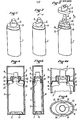
- Figure 1 is a general perspective view of an ovalized section vaporizer in the use position;
- Figure 2 is a view after rotation of the lock to ensure unlocking;
- Figure 3 is a view with the cover removed;
- Figure 4 is a sectional view through the plane of the major axis, the sprayer being provided with a cover;
- Figure 4a is a detail view of Figure 4;
- Figure 5 is a sectional view through the plane of the minor axis;
- Figure 5a is a detail view of Figure 5;
- Figure 6 is a top view, the cover being removed?
- Figure 7 is a detailed plan view of the hoop;
- Figure 8 is a plan view of the lock;
- Figure 9 is a view from below;
- Figure 10 is a sectional view through X-X of Figure 8;
- FIG. 11 is an elevation view with partial section through XI-XI of FIG. 8 and
- FIG. 12 is an elevation view through XII-XII of FIG. 8.
- the reference 1 designates the body of the envelope of the vaporizer
- the reference 2 the hood or cap which is fixed on the body to enclose the spray head
- the reference 3 indicates the refill
- reference 5 the hoop or cover of the envelope body
- reference 6 the latch and reference 7 the elastic cushion placed at the bottom of the envelope.
- the body 1 of the spray envelope as the cover 2 are made of a material having a beautiful surface appearance. They are cylindrical in shape with a director or oval cross section.
- the body 1 presents in its su a thinned part 8 for fitting together by the skirt 9 of the hoop 5.
- This part 8 carries, at the two diametrically opposite points of the minor axis of the straight section, tongues 10 projecting inwards, the outline of the edge inside of these tabs being ovalized.
- the cover 2 fits into the closure on a step 11 of the skirt 9 of the hoop and is held there removably for snap-fastening of the pins 12 provided on the cylindrical face of this step in corresponding notches provided near the edge of the internal surface of the cover.
- the refill 3 is made of a material insensitive to the p ro- Duit conditioning and usually made of glass. On its neck is crimped a plug 13 which holds the pump and the plunger 4 of the spraying member of the known type.
- the refill section is such that it can be engaged in the body 1 of the envelope. For this purpose its side faces have recessed portions 14 to allow the passage of the tongues 10.
- the refill is supported at the bottom of the body on the elastic cushion 7 which is constituted by a ring carrying elastic tongues 15 directed radially towards the center .
- the hoop 5 constitutes a cover which, as described above, maintains the refill 3 in the body 1. It fits by its skirt 9 on the thinned edge 8 of the body and, by the step 11, inside the free edge of the cover 2. It has in its upper surface an orifice designated by the general reference 16, this orifice being oblong with its largest dimension along the major axis of the oval of the hoop.
- the two ends of the orifice 16 located on the major axis form notches 17 for the passage of the stud tabs 18 of the lock which will be described below.
- the hole is delimited by two arcs of circles 20 and 21 centered on the axis of the oval, the arc of circle 20 having a radius slightly larger than the arc of circle 21.
- These parts 20-21 are connected to the other corner 22 of the notches 17 by arcs of circles 23-24 having respectively the same radii as the arcs of circles 21 and 20.
- the connection between the circular arcs 20-23 and 21-24 forms a stop for rotation 25.
- the upper surface 26 of the hoop is ovoidly curved to ensure a cam effect with the lower face of the lock.
- the lock 6 comprises a bowl-shaped body 27 of oval cross section with a skirt 28. From the two points at the ends of the minor axis, the skirt 28 is extended by lugs 29 which carry the lugs 18. The spacing of the lugs 18 and the length of the legs 29 are such that, when the lock is in abutment on the upper face of the hoop 5 and rotated so that the lugs are oriented along the minor axis of the hoop, the lugs 18 come to engage under the tongues 10 of body 1 of the envelope.
- each of the tabs carries, below the edge of the skirt 28, a bead 32 which is distant from the surface containing the edge of the skirt 28 of a little more than the thickness of the hoop to allow fixing, by snap-fastening of these beads under the edge of the orifice 16 of the hoop, of said latch 6 on the hoop 5.
- the surface of the edge of the latch adapts to the camber of the upper surface of the hoop.
- the bottom of the lock has in its center a circular orifice 33 for the passage of the plunger 4 of the pump.
- the mounting of the latch 6 on the hoop 5 is carried out by engaging the lugs 29 carrying the pins 18 in the notches 17, with the lug 30 in the cylindrical sector larger radius in front of the circular arc 20 of the orifice 16.
- the joining is then done by forcing the latch 6 on the hoop to pass the beads 32 under the surface of the hoop.
- the lock 6 can then rotate relative to the hoop 5, the amplitude of the rotation being limited to 90 ° by abutment of the edges of the tongue in a cylindrical sector 30 of larger radius against the connections 25.
- the hoop 5 In the closed position of the vaporizer, the hoop 5 is fitted by its skirt 9 on the thinned edge 8 of the body 1 of the envelope and maintains the refill 3 with a slight compression of the elastic cushion 7.
- the pins 18 are engaged under the tabs 10, which blocks the hoop in position on the body 1 of the envelope.
- the lock 6 To recharge the vaporizer, that is to say to change the refill 3, the lock 6 is turned a quarter of a turn in the direction of the arrow F (FIG. 2), which releases the pins 18 from the tongues 10 and the assembly constituted by the hoop 5 and the latch 6 can then be extracted in the direction of the arrow S (FIG. 3).
- closing is carried out by reverse operations.
Abstract
Description
La présente invention concerne plus spécialement les vaporisateurs dits rechargeables comportant un étui ou enveloppe extérieure présentant un bel aspect décoratif et qui peut être d'un prix de revient élevé et un conteneur intérieur dit "recharge" en un matériau tel que le verre, le métal ou une matière plastique qui est d'un prix de revient plus faible et qui peut être jeté après épuisement du produit qu'il contient. L'enveloppe extérieure est d'une manière usuelle constituée en deux parties qui peuvent être séparées pour permettre d'y insérer la recharge. Les deux parties forment, l'une la paroi latérale et le fond ou la partie supérieure, l'autre inversement la partie supérieure dite couvercle ou le fond.The present invention relates more specifically to so-called refillable vaporizers comprising a case or outer envelope having a beautiful decorative appearance and which may be of a high cost price and an inner container known as a "refill" made of a material such as glass, metal or a plastic material which has a lower cost price and which can be discarded after the product it contains has been used up. The outer envelope is usually made up of two parts which can be separated to allow the refill to be inserted therein. The two parts form, one the side wall and the bottom or the upper part, the other inversely the upper part called the cover or the bottom.
Le problème rencontré dans la réalisation de ces vaporisateurs rechargeables réside essentiellement dans l'assemblage des deux parties de l'enveloppe extérieure, cet assemblage devant assurer une bonne solidarisation des deux parties pour éviter une ouverture accidentelle, ce qui exclut les assemblages à simple emboîtement par frottement. Les assemblages les plus couramment utilisés sont ceux dits à vis ou à baïonnette. Ces assemblages ne sont toutefois utilisables que dans le cas d'assemblage entre deux sections circulaires ou sensiblement circulaires. L'assemblage à vis oblige à des épaisseurs plus grandes puisque les filets doivent être taillés dans les épaisseurs des jupes qui s'emboîtent et il nécessite de prévoir des reliefs extérieurs sur les deux parties pour permettre d'exercer manuellement le couple de vissage et de dévissage, ce dernier notamment pouvant être très élevé dans le cas d'un encrassement ou difficile à produire avec des surfaces de prise grasses ou mouillées. Ces prises extérieures nuisent à l'aspect d'ensemble de l'enveloppe. L'assemblage à baïonnette présente les mêmes inconvénients quoiqu'il permette, si l'on accepte un léger jeu entre la jupe extérieure et la jupe d'emboîtement interne, une légère ovalisation de la section.The problem encountered in the production of these vaporizers Rechargeable essentially resides in the assembly of the two parts of the outer casing, this assembly having to ensure good joining of the two parts to avoid accidental opening, which excludes assemblies with simple interlocking by friction. The most commonly used assemblies are those called screw or bayonet. These assemblies can however only be used in the case of assembly between two circular or substantially circular sections. The screw assembly requires greater thicknesses since the threads must be cut in the thicknesses of the skirts which fit together and it requires the provision of external reliefs on the two parts to allow manual exertion of the screwing and unscrewing, the latter in particular being able to be very high in the case of fouling or difficult to produce with greasy or wet grip surfaces. These external sockets detract from the overall appearance of the envelope. The bayonet connection has the same disadvantages, although it allows, if we accept a slight clearance between the outer skirt and the internal interlocking skirt, a slight ovalization of the section.
Dès que la section de l'enveloppe extérieure s'écarte de la forme circulaire, le seul assemblage connu à ce jour est l'assemblage à emboîtement à friction.As soon as the section of the outer casing departs from the circular shape, the only assembly known to date is the friction interlocking assembly.
Or, pour des raisons esthétiques ou d'encombrement, on cherche fréquemment des formes non circulaires de section carrée, polygonale, rectangulaire ou ovale. Le même problème se pose d'ailleurs avec tous les conteneurs de même définition que l'étui ou l'enveloppe d'un vaporisateur rechargeable tels que des coffrets qui doivent pouvoir être ouverts pour donner accès aux produits qu'ils contiennent.However, for aesthetic or bulk reasons, one frequently seeks non-circular shapes of square, polygonal, rectangular or oval section. The same problem also arises with all containers of the same definition as the case or the envelope of a refillable vaporizer such as boxes which must be able to be opened to give access to the products which they contain.
Le résultat est atteint, conformément à l'invention et selon une première caractéristique, par'le fait que dans une enveloppe en deux parties assemblées par emboîtement de forme de jupes non cylindriques, la jupe interne présente, dans au moins deux parties opposées, distantes angulairement des parties de la section présentant le plus grand écartement, des tenons en saillies vers l'extérieur ou des rainures et la pièce portant la jupe externe comporte un verrou monté à rotation autour de son centre géométrique et présentant deux ailes opposées susceptibles par rotation, à l'aide d'un bouton de commande faisant saillie au-dessus de la surface supérieure de ladite pièce, d'être engagées sous lesdits tenons ou dans lesdites rainures.The result is achieved, in accordance with the invention and according to a first characteristic, by the fact that in an envelope in two parts assembled by interlocking in the form of skirts non-cylindrical, the internal skirt has, in at least two opposite parts, angularly distant from the parts of the section having the greatest spacing, tenons projecting outwards or grooves and the part carrying the external skirt has a latch mounted rotating around its geometric center and having two opposite wings capable of rotating, using a control button projecting above the upper surface of said part, to be engaged under said studs or in said grooves .
De préférence le verrou comporte des butées limitant son angle de rotation et son bouton de commande a une section non cylindrique pour améliorer la prise permettant d'exercer le couple de verrouillage ou de déverrouillage.Preferably the lock has stops limiting its angle of rotation and its control button has a non-cylindrical section to improve the grip allowing to exert the locking or unlocking torque.
Selon une autre caractéristique applicable notamment aux pulvérisateurs ou vaporisateurs, la partie portant le verrou constitue le couvercle de l'enveloppe et le bouton de commande est creux et comporte un passage axial pour le passage de l'organe de pulvérisation.According to another characteristic applicable in particular to sprayers or sprays, the part carrying the lock constitutes the cover of the envelope and the control button is hollow and has an axial passage for the passage of the spraying member.
Selon une autre caractéristique un organe élastique compressible est monté au fond du corps de l'enveloppe et pousse la recharge contre le couvercle pour mettre en appui les ailes du verrou contre les surfaces d'appui des tenons ou rainures.According to another characteristic, a compressible elastic member is mounted at the bottom of the body of the envelope and pushes the refill against the cover to support the wings of the lock against the bearing surfaces of the tenons or grooves.
Selon encore une autre caractéristique, l'appui entre le bouton de commande et la surface d'appui sur le couvercle s'effectue selon une surface bombée non de révolution de manière à réaliser un effet de came élastique, le déverrouillage s'effectuant avec une compression supplémentaire de l'organe élastique.According to yet another characteristic, the pressing between the control button and the bearing surface on the cover takes place on a curved surface which is not of revolution so as to produce an elastic cam effect, the unlocking being effected with a additional compression of the elastic organ.
D'autres caractéristiques de l'invention apparaîtront à la lecture de la description détaillée d'un mode de réalisation d'un vaporisateur rechargeable, la description étant faite avec référence aux dessins ci-annexés dans lesquels.Other characteristics of the invention will appear on reading the detailed description of an embodiment of a rechargeable vaporizer, the description being made with reference to the attached drawings in which.
La figure 1 est une vue générale en perspective d'un vaporisateur de section ovalisée en position d'utilisation; la figure 2 en est une vue après rotation du verrou pour assurer le déverrouillage; la figure 3 en est une vue avec le couvercle enlevé; la figure 4 en est une vue en coupe par le plan du grand axe, le vaporisateur étant muni d'un capot,; la figure 4a est une vue de détail de la figure 4; la figure 5 en est une vue en coupe par le plan du petit axe; la figure 5a est une vue de détail de la figure 5; la figure 6 en est une vue par dessus, le capot étant enlevé? la figure 7 est une vue de détail en plan de la frette; la figure 8 est une vue en plan du verrou; la figure 9 en est une vue par dessous; la figure 10 en est une vue en coupe par X-X de figure 8; la figure 11 est une vue en élévation avec coupe partielle par XI-XI de figure 8 et la figure 12 est une vue en élévation par XII-XII de figure 8.Figure 1 is a general perspective view of an ovalized section vaporizer in the use position; Figure 2 is a view after rotation of the lock to ensure unlocking; Figure 3 is a view with the cover removed; Figure 4 is a sectional view through the plane of the major axis, the sprayer being provided with a cover; Figure 4a is a detail view of Figure 4; Figure 5 is a sectional view through the plane of the minor axis; Figure 5a is a detail view of Figure 5; Figure 6 is a top view, the cover being removed? Figure 7 is a detailed plan view of the hoop; Figure 8 is a plan view of the lock; Figure 9 is a view from below; Figure 10 is a sectional view through X-X of Figure 8; FIG. 11 is an elevation view with partial section through XI-XI of FIG. 8 and FIG. 12 is an elevation view through XII-XII of FIG. 8.
Dans les dessins, la référence 1 désigne le corps de l'enveloppe du vaporisateur, la référence 2 le capot ou capuchon qui vient se fixer sur le corps pour enfermer la tête de vaporisation, la référence 3 désigne la recharge, la référence 4 le poussoir de la pompe de vaporisation de la recharge=, la référence 5 la frette ou couvercle du corps de l'enveloppe, la référence 6 le verrou et la référence 7 le coussin élastique placé au fond de l'enveloppe.In the drawings, the
Le corps 1 de l'enveloppe du vaporisateur comme le capot 2 sont réalisés en un matériau présentant un bel aspect de surface. Ils sont de forme cylindrique avec une directrice ou section droite ovale. Le corps 1 présente à sa partie supérieure une partie amincie 8 pour l'emboîtement par la jupe 9 de la frette 5. Cette partie 8 porte, aux deux points diamétralement opposés du petit axe de la section droite, des languettes 10 en saillie vers l'intérieur, le tracé du bord intérieur de ces languettes étant ovalisé.The
Le capot 2 s'emboîte pour la fermeture sur un redan 11 de la jupe 9 de la frette et il y est maintenu de manière amovible pour encliquetage de tétons 12 prévus sur la face cylindrique de ce redan dans des encoches correspondantes prévues près du bord de la surface interne du capot.The
La recharge 3 est constituée en un matériau insensible au pro- duit conditionné et le plus souvent en verre. Sur son goulot est serti un bouchon 13 qui maintient la pompe et le poussoir 4 de l'organe de pulvérisation du type connu. La section de la recharge est telle qu'elle puisse être engagée dans le corps 1 de l'enveloppe. A cet effet ses faces latérales présentent des parties en creux 14 pour permettre le passage des languettes 10. La recharge s'appuie au fond du corps sur le coussin élastique 7 qui est constitué par une bague portant des languettes élastiques 15 dirigées radialement vers le centre.The
La frette 5 constitue un couvercle qui, comme décrit ci-dessus, maintient la recharge 3 dans le corps 1. Elle s'emboîte par sa jupe 9 sur le bord aminci 8 du corps et, par le redan 11, à l'intérieur du bord libre du capot 2. Elle comporte dans sa surface supérieure un orifice désigné par la référence générale 16, cet orifice étant oblong avec sa plus grande dimension selon le grand axe de l'ovale de la frette. Les deux extrémités de l'orifice 16 se trouvant sur le grand axe forment des encoches 17 pour le passage des pattes à tenons 18 du verrou qui sera décrit ci-après. A partir des coins opposés 19 de ces encoches, l'prifice est délimité par deux arcs de cercles 20 et 21 centrés sur l'axe de l'ovale, l'arc de cercle 20 ayant un rayon légèrement plus grand que l'arc de cercle 21. Ces parties 20-21 sont raccordées à l'autre coin 22 des encoches 17 par des arcs de cercles 23-24 ayant respectivement les mêmes rayons que les arcs de cercles 21 et 20. Le raccordement entre les arcs de cercle 20-23 et 21-24 forme une butée à la rotation 25, La surface supérieure 26 de la frette est bombée de façon ovoide pour assurer un effet de came avec la face inférieure du verrou.The
Le verrou 6 comporte un corps en cuvette 27 de section droite ovale avec une jupe 28. A partir des deux points aux extrémités du petit axe, la jupe 28 se prolonge par des pattes 29 qui portent les tenons 18. L'écartement des tenons 18 et la longueur des pattes 29 sont tels que, lorsque le verrou est en appui sur la face supérieure de la frette 5 et tourné pour que les tenons soient orientés selon le petit axe de la frette, les tenons 18 viennent s'engager sous les languettes 10 du corps 1 de l'enveloppe.The
A partir du fond 27 de la cuvette descendent deux languettes en secteurs cylindriques 30 et 31 centrés sur l'axe du verrou et symétriques par rapport au grand axe de l'ovale, les rayons extérieurs de ces secteurs cylindriques 30 et 31 correspondant aux rayons des arcs de cercle 20 et 21 respectivement et leur développement angulaire étant voisin de 90°. Chacune des languettes porte, en-dessous du bord de la jupe 28, un bourrelet 32 qui est distant de la surface contenant le bord de la jupe 28 d'un peu plus que l'épaisseur de la frette pour permettre la fixation, par encliquetage de ces bourrelets sous le bord de l'orifice 16 de la frette, dudit verrou 6 sur la frette 5. La surface du bord du verrou s'adapte au bombé de la surface supérieure de la frette. Le fond du verrou présente en son centre un orifice circulaire 33 pour le passage du poussoir 4 de la pompe.From the
Comme exposé ci-dessus, le montage du verrou 6 sur la frette 5 s'effectue en engageant les pattes 29 portant les tenons 18 dans les encoches 17, avec la patte 30 en secteur cylindrique de plus grand rayon en face de l'arc de cercle 20 de l'orifice 16. La solidarisation se fait alors en forçant le verrou 6 sur la frette pour faire passer les bourrelets 32 sous la surface de la frette. Le verrou 6 peut alors tourner par rapport à la frette 5, l'amplitude de la rotation étant limitée à 90° par butée des bords de la languette en secteur cylindrique 30 de plus grand rayon contre les raccordements 25.As explained above, the mounting of the
En position de fermeture du vaporisateur, la frette 5 est emboîtée par sa jupe 9 sur le bord aminci 8 du corps 1 de l'enveloppe et maintient la recharge 3 avec une légère compression du coussin élastique 7. Les tenons 18 sont engagés sous les languettes 10, ce qui bloque la frette en position sur le corps 1 de l'enveloppe. Pour recharger le vaporisateur, c'est-à-dire changer la recharge 3, on fait tourner le verrou 6 d'un quart de tour dans le sens de la flèche F (figure 2), ce qui dégage les tenons 18 des languettes 10 et l'ensemble constitué par la frette 5 et le verrou 6 peut alors être extrait dans le sens de la flèche S (figure 3). Après échange de la recharge 3, la fermeture s'effectue par les manoeuvres inverses.In the closed position of the vaporizer, the
Claims (7)
caractérisé en ce que la jupe interne (8) présente dans au moins deux parties opposées, distantes angulairement des parties de la section présentant le plus grand écartement, des tenons (10) en saillie vers l'intérieur ou des rainures, la pièce (5) portant la jupe externe (9) comportant un verrou (6) monté à rotation autour de son centre géométrique et présentant deux ailes opposées (18) susceptibles, par rotation à l'aide d'un bouton de commande (27) faisant saillie au-dessus de la surface supérieure (26) de ladite pièce (5), d'être engagées sous lesdits tenons (10) ou dans lesdites rainures.1. Two-part case with locking assembly, in particular rechargeable vaporizer comprising two parts (1-5) assembled by interlocking in the form of non-cylindrical skirts (8-9),
characterized in that the internal skirt (8) has in at least two opposite parts, angularly distant from the parts of the section having the greatest spacing, pins (10) projecting inwards or grooves, the part (5 ) carrying the outer skirt (9) comprising a latch (6) rotatably mounted around its geometric center and having two opposite wings (18) capable, by rotation using a control button (27) projecting at above the upper surface (26) of said part (5), to be engaged under said studs (10) or in said grooves.
caractérisé en ce que le verrou (6) comporte des butées (25-30) limitant son angle de rotation et en ce que son bouton de commande (27) a une forme non circulaire.2. A case according to claim 1,
characterized in that the lock (6) has stops (25-30) limiting its angle of rotation and in that its control button (27) has a non-circular shape.
caractérisé en ce que la partie (5) portant le verrou (6) constitue le couvercle de l'enveloppe et le bouton de commande (27) est creux et comporte un passage axial .33 pour le passage de l'organe de pulvérisation (4).3. A case according to any one of claims 1 and 2 constituting the envelope of a refill (3) forming a sprayer or vaporizer,
characterized in that the part (5) carrying the latch (6) constitutes the cover of the envelope and the control button (27) is hollow and has an axial passage .33 for the passage of the spraying member (4 ).
Priority Applications (1)
| Application Number | Priority Date | Filing Date | Title |
|---|---|---|---|
| AT85401105T ATE33238T1 (en) | 1984-06-15 | 1985-06-05 | CASE COMPOSED OF TWO PARTS WITH LOCKING ELEMENTS FOR THEIR CONNECTION, PARTICULARLY REFILLABLE ATOMIZER. |
Applications Claiming Priority (2)
| Application Number | Priority Date | Filing Date | Title |
|---|---|---|---|
| FR8409404A FR2565799B1 (en) | 1984-06-15 | 1984-06-15 | TWO-PART CASE WITH LOCKING ASSEMBLY, ESPECIALLY RECHARGEABLE VAPORIZER |
| FR8409404 | 1984-06-15 |
Publications (2)
| Publication Number | Publication Date |
|---|---|
| EP0168285A1 true EP0168285A1 (en) | 1986-01-15 |
| EP0168285B1 EP0168285B1 (en) | 1988-03-30 |
Family
ID=9305068
Family Applications (1)
| Application Number | Title | Priority Date | Filing Date |
|---|---|---|---|
| EP85401105A Expired EP0168285B1 (en) | 1984-06-15 | 1985-06-05 | Case comprising two parts with locking means for their connection, especially a rechargeable vaporiser |
Country Status (5)
| Country | Link |
|---|---|
| US (1) | US4676408A (en) |
| EP (1) | EP0168285B1 (en) |
| AT (1) | ATE33238T1 (en) |
| DE (1) | DE3562007D1 (en) |
| FR (1) | FR2565799B1 (en) |
Cited By (6)
| Publication number | Priority date | Publication date | Assignee | Title |
|---|---|---|---|---|
| EP0260518A2 (en) * | 1986-09-16 | 1988-03-23 | Tokai Corporation | Portable aerosol container |
| EP0509872A1 (en) * | 1991-04-19 | 1992-10-21 | L'oreal | Apparatus to diffuse a liquid product into small droplets |
| EP0697223A3 (en) * | 1994-07-20 | 1996-06-05 | Plastiape Spa | Pocket-sized nebuliser for delivering drugs to the oral cavity |
| FR2750113A1 (en) * | 1996-06-24 | 1997-12-26 | Valois | DISTRIBUTION DEVICE WITH OPERATION SECURITY AND RECHARGE OF SUCH A DEVICE |
| WO2007084322A1 (en) * | 2006-01-18 | 2007-07-26 | The Procter & Gamble Company | Package closure |
| WO2022018365A1 (en) * | 2020-07-24 | 2022-01-27 | Techniplast | Liquid extraction machine and associated liquid extraction method |
Families Citing this family (27)
| Publication number | Priority date | Publication date | Assignee | Title |
|---|---|---|---|---|
| DE9107249U1 (en) * | 1991-06-12 | 1992-10-15 | Ortner, Georg, 5000 Koeln, De | |
| US5356049A (en) * | 1993-03-29 | 1994-10-18 | Eastman Kodak Company | Hand pump assembly with a pump mechanism which is independent of the pump housing |
| US5499747A (en) * | 1994-05-16 | 1996-03-19 | Quennessen; Bernard R. | Retractable carrier for, and in combination with, a vial-type fluid dispenser |
| US5526960A (en) * | 1994-12-14 | 1996-06-18 | Fragrance Systems International, Inc. | Perfume dispenser with replaceable cartridges |
| US5586694A (en) * | 1994-12-14 | 1996-12-24 | Fragrance Systems International, Inc. | Perfume applicator with replaceable cartridges |
| US5862960A (en) * | 1997-02-28 | 1999-01-26 | S. C. Johnson & Son, Inc. | Aerosol dispenser |
| US20040079361A1 (en) * | 2001-01-17 | 2004-04-29 | Clayton Colin D. | Medicinal aerosols |
| US7467908B2 (en) * | 2003-12-24 | 2008-12-23 | Lucas Publications, Inc. | Fluid dispenser assembly |
| DE102005014397A1 (en) * | 2005-03-24 | 2006-09-28 | Wella Ag | spray applicator |
| US20090198199A1 (en) * | 2008-02-01 | 2009-08-06 | Drug Enhancement Company Of America, Llc | Inert container and dispenser |
| USD636668S1 (en) | 2008-03-24 | 2011-04-26 | Mary Kay Inc. | Dip tubes |
| US8376192B2 (en) | 2008-03-24 | 2013-02-19 | Mary Kay Inc. | Apparatus for dispensing fluids using a press-fit diptube |
| USD588916S1 (en) | 2008-04-02 | 2009-03-24 | Mary Kay Inc. | Container |
| US9789502B2 (en) | 2008-06-05 | 2017-10-17 | Mary Kay Inc. | Apparatus for dispensing fluids using a removable bottle |
| US8668401B2 (en) | 2010-04-05 | 2014-03-11 | Frank Francavilla | Mascara dispensing device |
| JP6180885B2 (en) * | 2013-10-31 | 2017-08-16 | 株式会社吉野工業所 | Aerosol shoulder cover |
| USD757564S1 (en) * | 2014-08-07 | 2016-05-31 | Natura Cosmeticos S.A. | Perfume bottle |
| US10485939B2 (en) * | 2015-10-01 | 2019-11-26 | Presspart Manufacturing Limited | Metered dose inhaler canister and shroud |
| USD778170S1 (en) * | 2015-10-02 | 2017-02-07 | Maywell Co. Ltd. | Container |
| US10688675B2 (en) * | 2017-01-17 | 2020-06-23 | The Gillette Company Llc | Personal care bottle and method of manufacture |
| CN206485775U (en) | 2017-01-19 | 2017-09-12 | 科丝美诗(中国)化妆品有限公司 | A kind of lid and the packaging with the lid |
| USD895346S1 (en) * | 2017-01-25 | 2020-09-08 | Tsann Kuen (Zhangzhou) Enterprise Co., Ltd. | Grill |
| CN110582451A (en) * | 2017-05-04 | 2019-12-17 | 荷兰联合利华有限公司 | package and refill container |
| CN109303355A (en) * | 2018-11-02 | 2019-02-05 | 深圳市合元科技有限公司 | The atomizer and electronic cigarette of removable atomization core |
| US11608669B1 (en) * | 2021-10-01 | 2023-03-21 | Schlage Lock Company Llc | Door operator housing assembly |
| WO2023089246A1 (en) * | 2021-11-22 | 2023-05-25 | Chanel Parfums Beaute | Assembly comprising a bottle, a decorative cap, and a system for attaching the decorative cap to the bottle |
| US11772111B1 (en) * | 2022-09-16 | 2023-10-03 | Branded AcquiCo No 5, LLC | Dispenser |
Citations (3)
| Publication number | Priority date | Publication date | Assignee | Title |
|---|---|---|---|---|
| DE2460407A1 (en) * | 1974-12-20 | 1976-06-24 | Sanner Kg Friedr | Tamper proof bottle stopper - two sections for stopper and bottle connected across break points |
| FR2344340A1 (en) * | 1976-03-16 | 1977-10-14 | Anmeghian Pierre | Decorative holder for pressurised deodorant container - has wall mounting with container inside operated by pressing top for side spray |
| FR2537093A1 (en) * | 1982-12-03 | 1984-06-08 | Valois Sa | Case with push button control |
Family Cites Families (3)
| Publication number | Priority date | Publication date | Assignee | Title |
|---|---|---|---|---|
| US3080989A (en) * | 1960-10-31 | 1963-03-12 | Dorset Rex Inc | Refillable holder for bottles and the like |
| US3157317A (en) * | 1961-08-28 | 1964-11-17 | Landers Frary & Clark | Holder for bottles and the like |
| US3198399A (en) * | 1961-10-05 | 1965-08-03 | Valve Corp Of America | Hand-held aerosol device |
-
1984
- 1984-06-15 FR FR8409404A patent/FR2565799B1/en not_active Expired
-
1985
- 1985-06-05 DE DE8585401105T patent/DE3562007D1/en not_active Expired
- 1985-06-05 AT AT85401105T patent/ATE33238T1/en not_active IP Right Cessation
- 1985-06-05 EP EP85401105A patent/EP0168285B1/en not_active Expired
- 1985-06-11 US US06/743,651 patent/US4676408A/en not_active Expired - Fee Related
Patent Citations (3)
| Publication number | Priority date | Publication date | Assignee | Title |
|---|---|---|---|---|
| DE2460407A1 (en) * | 1974-12-20 | 1976-06-24 | Sanner Kg Friedr | Tamper proof bottle stopper - two sections for stopper and bottle connected across break points |
| FR2344340A1 (en) * | 1976-03-16 | 1977-10-14 | Anmeghian Pierre | Decorative holder for pressurised deodorant container - has wall mounting with container inside operated by pressing top for side spray |
| FR2537093A1 (en) * | 1982-12-03 | 1984-06-08 | Valois Sa | Case with push button control |
Cited By (10)
| Publication number | Priority date | Publication date | Assignee | Title |
|---|---|---|---|---|
| EP0260518A2 (en) * | 1986-09-16 | 1988-03-23 | Tokai Corporation | Portable aerosol container |
| EP0260518A3 (en) * | 1986-09-16 | 1989-09-06 | Tokai Corporation | Portable aerosol container |
| EP0509872A1 (en) * | 1991-04-19 | 1992-10-21 | L'oreal | Apparatus to diffuse a liquid product into small droplets |
| US5242090A (en) * | 1991-04-19 | 1993-09-07 | L'oreal | Device for spraying a liquid product, especially a hair product, in fine droplets |
| EP0697223A3 (en) * | 1994-07-20 | 1996-06-05 | Plastiape Spa | Pocket-sized nebuliser for delivering drugs to the oral cavity |
| FR2750113A1 (en) * | 1996-06-24 | 1997-12-26 | Valois | DISTRIBUTION DEVICE WITH OPERATION SECURITY AND RECHARGE OF SUCH A DEVICE |
| WO1997049620A1 (en) * | 1996-06-24 | 1997-12-31 | Valois S.A. | Dispensing device with safe operation control and refill for same |
| WO2007084322A1 (en) * | 2006-01-18 | 2007-07-26 | The Procter & Gamble Company | Package closure |
| WO2022018365A1 (en) * | 2020-07-24 | 2022-01-27 | Techniplast | Liquid extraction machine and associated liquid extraction method |
| FR3112765A1 (en) * | 2020-07-24 | 2022-01-28 | Techniplast | Liquid extraction machine and associated liquid extraction method |
Also Published As
| Publication number | Publication date |
|---|---|
| FR2565799B1 (en) | 1986-09-05 |
| EP0168285B1 (en) | 1988-03-30 |
| DE3562007D1 (en) | 1988-05-05 |
| ATE33238T1 (en) | 1988-04-15 |
| US4676408A (en) | 1987-06-30 |
| FR2565799A1 (en) | 1985-12-20 |
Similar Documents
| Publication | Publication Date | Title |
|---|---|---|
| EP0168285B1 (en) | Case comprising two parts with locking means for their connection, especially a rechargeable vaporiser | |
| EP0633197B1 (en) | Combination of a, by relative rotation, interlocking container and closure, as well as the application of such a combination | |
| FR2567104A1 (en) | Stopper device for flask | |
| CA2353719A1 (en) | Closure cap for container with fixing flange | |
| EP0308289A1 (en) | Container with a removable cap having lateral generatrices aligned with those of the container | |
| EP0839469A1 (en) | Case with assisted opening | |
| EP0072294A1 (en) | Inviolable telescopable cover for a container with a many-sided section | |
| EP0684187B1 (en) | Pouring cap with tamper-evident closure | |
| FR2543923A1 (en) | Pressurised container of the "aerosol can" type | |
| EP0899203A1 (en) | Assembly of two elements, mounted freely rotatable relative to each other and irreversibly connected together | |
| CH659634A5 (en) | UNIT FOR THE PACKAGING AND APPLICATION OF A VARNISH TYPE SUBSTANCE. | |
| EP0227510A1 (en) | Locking device for an aerosol dispenser | |
| EP0004501B1 (en) | Closure means for a container with a screw-threaded neck | |
| FR2767119A1 (en) | RELEASABLE HINGE HOUSING AND SELF-SEALING LIPSTICK | |
| JP2004512234A (en) | Positive positioning system for lids and containers | |
| EP3871558A1 (en) | Housing, in particular for cosmetic products | |
| FR2676997A1 (en) | Child-proof service stopper | |
| CA2422754A1 (en) | Pourer with improved locking and cap equipped with same | |
| EP0010028B1 (en) | Closure element with self-orientation of the plug | |
| EP0650903A2 (en) | Fuel filler cap for vehicles | |
| FR2882902A1 (en) | Pasty or solid product e.g. cosmetic product, containing pot, has closing unit actuated by manual pressure and including upper closing unit integrated to cover that is integrated with body using hinge | |
| FR2715384A1 (en) | Rechargeable container for cosmetic cream | |
| EP3829387B1 (en) | Device for packaging and applying a cosmetic product | |
| WO2023281028A1 (en) | Refillable cup for a pot for dispensing a cosmetic product | |
| EP3034177A1 (en) | System for storing a fluid product, comprising a bottle in an outer covering |
Legal Events
| Date | Code | Title | Description |
|---|---|---|---|
| PUAI | Public reference made under article 153(3) epc to a published international application that has entered the european phase |
Free format text: ORIGINAL CODE: 0009012 |
|
| AK | Designated contracting states |
Designated state(s): AT BE CH DE GB IT LI LU NL SE |
|
| 17P | Request for examination filed |
Effective date: 19860625 |
|
| 17Q | First examination report despatched |
Effective date: 19861222 |
|
| ITF | It: translation for a ep patent filed |
Owner name: ING. ZINI MARANESI & C. S.R.L. |
|
| GRAA | (expected) grant |
Free format text: ORIGINAL CODE: 0009210 |
|
| AK | Designated contracting states |
Kind code of ref document: B1 Designated state(s): AT BE CH DE GB IT LI LU NL SE |
|
| PG25 | Lapsed in a contracting state [announced via postgrant information from national office to epo] |
Ref country code: NL Effective date: 19880330 Ref country code: AT Effective date: 19880330 |
|
| REF | Corresponds to: |
Ref document number: 33238 Country of ref document: AT Date of ref document: 19880415 Kind code of ref document: T |
|
| PG25 | Lapsed in a contracting state [announced via postgrant information from national office to epo] |
Ref country code: SE Effective date: 19880331 |
|
| REF | Corresponds to: |
Ref document number: 3562007 Country of ref document: DE Date of ref document: 19880505 |
|
| NLV1 | Nl: lapsed or annulled due to failure to fulfill the requirements of art. 29p and 29m of the patents act | ||
| GBV | Gb: ep patent (uk) treated as always having been void in accordance with gb section 77(7)/1977 [no translation filed] | ||
| PG25 | Lapsed in a contracting state [announced via postgrant information from national office to epo] |
Ref country code: GB Free format text: LAPSE BECAUSE OF NON-PAYMENT OF DUE FEES Effective date: 19881124 |
|
| BECN | Be: change of holder's name |
Effective date: 19880330 |
|
| PLBE | No opposition filed within time limit |
Free format text: ORIGINAL CODE: 0009261 |
|
| STAA | Information on the status of an ep patent application or granted ep patent |
Free format text: STATUS: NO OPPOSITION FILED WITHIN TIME LIMIT |
|
| 26N | No opposition filed | ||
| REG | Reference to a national code |
Ref country code: CH Ref legal event code: PFA Free format text: TECHPACK INTERNATIONAL |
|
| ITTA | It: last paid annual fee | ||
| PGFP | Annual fee paid to national office [announced via postgrant information from national office to epo] |
Ref country code: BE Payment date: 19930526 Year of fee payment: 9 |
|
| PGFP | Annual fee paid to national office [announced via postgrant information from national office to epo] |
Ref country code: LU Payment date: 19930527 Year of fee payment: 9 |
|
| PGFP | Annual fee paid to national office [announced via postgrant information from national office to epo] |
Ref country code: CH Payment date: 19930616 Year of fee payment: 9 |
|
| PGFP | Annual fee paid to national office [announced via postgrant information from national office to epo] |
Ref country code: DE Payment date: 19930830 Year of fee payment: 9 |
|
| EPTA | Lu: last paid annual fee | ||
| PG25 | Lapsed in a contracting state [announced via postgrant information from national office to epo] |
Ref country code: LU Free format text: LAPSE BECAUSE OF NON-PAYMENT OF DUE FEES Effective date: 19940605 |
|
| PG25 | Lapsed in a contracting state [announced via postgrant information from national office to epo] |
Ref country code: LI Effective date: 19940630 Ref country code: CH Effective date: 19940630 Ref country code: BE Effective date: 19940630 |
|
| BERE | Be: lapsed |
Owner name: TECHPACK INTERNATIONAL Effective date: 19940630 |
|
| REG | Reference to a national code |
Ref country code: CH Ref legal event code: PL |
|
| PG25 | Lapsed in a contracting state [announced via postgrant information from national office to epo] |
Ref country code: DE Effective date: 19950301 |