EP0168216A2 - Bau eines Fernsprechers von welchem ein Teil invertiert montierbar ist - Google Patents
Bau eines Fernsprechers von welchem ein Teil invertiert montierbar ist Download PDFInfo
- Publication number
- EP0168216A2 EP0168216A2 EP85304772A EP85304772A EP0168216A2 EP 0168216 A2 EP0168216 A2 EP 0168216A2 EP 85304772 A EP85304772 A EP 85304772A EP 85304772 A EP85304772 A EP 85304772A EP 0168216 A2 EP0168216 A2 EP 0168216A2
- Authority
- EP
- European Patent Office
- Prior art keywords
- telephone set
- handset
- set structure
- mounting member
- radio equipment
- Prior art date
- Legal status (The legal status is an assumption and is not a legal conclusion. Google has not performed a legal analysis and makes no representation as to the accuracy of the status listed.)
- Granted
Links
- 230000008878 coupling Effects 0.000 claims abstract description 9
- 238000010168 coupling process Methods 0.000 claims abstract description 9
- 238000005859 coupling reaction Methods 0.000 claims abstract description 9
- 230000001012 protector Effects 0.000 claims description 4
- 238000010276 construction Methods 0.000 description 2
- 238000004891 communication Methods 0.000 description 1
- 230000000994 depressogenic effect Effects 0.000 description 1
- 238000012986 modification Methods 0.000 description 1
- 230000004048 modification Effects 0.000 description 1
- 230000000717 retained effect Effects 0.000 description 1
Images


Classifications
-
- H—ELECTRICITY
- H04—ELECTRIC COMMUNICATION TECHNIQUE
- H04M—TELEPHONIC COMMUNICATION
- H04M1/00—Substation equipment, e.g. for use by subscribers
- H04M1/02—Constructional features of telephone sets
- H04M1/04—Supports for telephone transmitters or receivers
- H04M1/06—Hooks; Cradles
Definitions
- the present invention relates to the structure of a telephone set and, more particularly, to the structure of a radiotelephone which is installed in a vehicle cabin or like confinement.
- a telephone for use in a vehicle is usually made up of a handset unit and a base unit which is physically separate from the handset unit.
- the base unit adapted to support the handset unit is provided with a volume control knob, a power switch and others on one of opposite side faces thereof, and a loudspeaker at the other side face.
- This kind of telephone applied to a vehicle is generally positioned at left of the driver's seat if the driver's seat is mounted at the right-hand side of the vehicle and at right of the driver's seat if it is mounted at the lefthand side, so that only one of the opposite side faces of the base unit opposes a person who is seated in the driver's seat.
- arranging the manipulable section inclusive of the volume control knob and power switch on, for example, the right face of the base unit is desirable from easy access standpoint for a vehicle of one type having a driver's seat at right but undesirable for a vehicle of the other type having a driver's seat at left, while arranging them on the left face of the base unit is desirable for the latter type of vehicle but undesirable for the former type of vehicle.
- a telephone set structure of the present invention comprises a handset having a transmitter and a receiver, a base for fixing the handset in place and accommodating circuits which are electrically interconnected to the transmitter and receiver of the handset, and a mounting member for mounting a manipulable section on one of opposite side faces thereof and a non-manipulable section on the other side face, the mounting member being constructed to be inserted into the base in such a manner that the opposite side faces are invertible to replace each other.
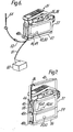
- a telephone set to which the present invention is applied includes a handset 1 and a base or handset support 100.
- the handset 1 comprises a microphone or transmitter and a receiver therein and is provided with dial buttons 2, a display 3 and others.
- the base 100 includes a coupling section 6 for fixing the handset 1 in place, a mounting member 5 which mounts thereon a power switch, a loudspeaker and others, and a casing 4 for accmmmodating the mounting member 5 and a circuit board on which necessary circuits are loaded.
- the mounting member 5 has a manipulable section arranged one side face thereof and provided with a volume control knob, a power switch and others, and a non-manipulable section arranged on the other side face and provided with a speaker grill and others.
- the member 5 is engageable with the casing 4 in such a manner that those opposite side faces are invertible in position to replace each other.
- the handset coupling section 6 is fastened to the casing 4 by screws or like fastening means and functions to fix the handset 1 in place.
- Electronic circuits built in the handset 1 are electrically connected by a curl code 7 to those which are installed in the casing 4.
- the handset coupling section 6 includes lugs 601 and 602 adapted to lock the handset 1 in position.
- the lug 602 is operatively connected with a push-button 604 such that it unlocks the handset 1 when the push-button 604 is depressed.
- Another lug 603 is spring-biased to serve the function of raising the handset 1 when the latter is released from the lug 602, so that the operator may easily hold the handset 1 for communication.
- the coupling section 6 is locked by a projection 402 extending from the casing 4 and fixed to the casing 4 by means of a screw (not shown) which is driven into a threaded hole 401.
- the mounting member 5 is provided with a power switch 501 and a volume control knob 502 on one side face and a speaker grill 504 (see Fig. 3) on the other side face. As shown in Fig. 3, a loudspeaker 503 is mounted to the member 5 in an inclined position so as to minimize the dead space.
- recesses 505 extend respectively at the four corners of the mounting member 5 to receive four lugs 405 which extend on the casing 4.
- the recesses 505 share the same configuration and dimensions, and so do the projections 405.
- the opposite side faces of the mounting member 5 share the same length. With such a structure, the member 5 may be inserted into the casing 4 with the both side faces held in an invertible positional relationship.
- the position of the manipulable section inclusive of the power switch 501 and volume control knob 502 and that of the non-manipulable section inclusive of the speaker grill 504 can be replaced merely by inverting the lateral orientation of the mounting member 5 relative to the casing 4.
- the casing 4 has a capacity great enough to accommodate not only the mounting member 5 but also a circuit board 403 which is loaded with electronic circuits (not shown).
- the casing 4 is notched to have a pair of recesses 404 for receiving the push-buttons 604 of the coupling section 6.
- the mounting member 5 is provided with a symmetrical configuration with respect to the casing 4.
- the four interengaging portions (405, 405) are identical with each other and, therefore, inverting the member 5 in the right-and-left direction is no problem. It follows that the telephone set shown and described is readily applicable to a vehicle regardless of the position of the driver's seat, that is, merely by inverting mounting member 5 to match it to a particular position of the driver's seat.
- the manipulable section inclusive of the power switch 501 may be located in a position which is easy for the main user of the telephone to make access.
- a telephone is made up of the handset 1 and the base 100 which is provided with a connector 35 at its bottom for electrical connection.
- a radio equipment body 37 capable of processing signals which are transmitted and received through an antenna 36 or 54 is provided with a connector 38 on one surface thereof for connection with the connector 35, and engaging portions 39 detachably engageable with the base 100.
- a connector 41 for connection with a power source and a connector 42 for connection with the antenna.
- a lug 44 extends from each of two opposing surfaces of the radio equipment body 37 to be engageable with a handle 43. Further a lug 46 extends from one of the surfaces of the radio equipment body 37 to be engageable with a base portion of the antenna 36.
- the radio equipment body 37 is fixed to a vehicle body or the like by means of a holder 47 which includes engaging portions 48a for removably retaining the equipment body 37, a connector 49 for making contact with the connector 41, and a connector 50 for making contact with the connector 42.
- the connector 49 is connected by a cable 51 to a power source 52 such as a battery adapted to power a vehicle, while the connector 50 is connected by a cable 53 and a relay connector 55 to the antenna 54 which is mounted on a vehicle body, for example.
- a protector 56 which functions as will be described is provided with engaging portions 48b which are the same in function as the engaging portions 48a, and a connector 57 for connection with the connector 42.
- a cable 58 extends out from the connector 57 and carries at its end a connector (or base portion) 45 to which the antenna 36 may be connected.
- a battery unit 59 has thereinside a battery and a battery charging circuit to serve as a portable power source.
- Engaging portions 48c Provided on one surface of the battery unit, or casing, 59 are engaging portions 48c which share the same function with the engaging portions 48a and 48b, a connector 60 for connection with the connector 41, and a connector 61 for connection with the connector 42.
- connectors 62 and 63 for connection with the connector 49 and the connector 50 (or connector 57), respectively.
- the radiotelephone having the above construction and arrangement is usable in different configurations as will be described, depending upon desired conditions of use.
- the holder 47 is utilized which is fixed to a vehicle body or the like and has the power source cable 51 connecting to the battery 52 and the antenna cable 53 to the antenna 54.
- the radio equipment body 37 is securely mounted to the holder 47 by the engaging portions 48a and this causes their power source connectors and antenna connectors to be interconnected.
- the base 100 of the telephone set 31 is mounted to the radio equipment body 37 through the engaging portions 39, setting up electric electrical connection between the connectors 35 and 38.
- the radiotelephone may be operated in a vehicle cabin or like confinement.
- the radio equipment 37 in the configuration of Fig. 6 is removed from the engaging portions 48a of the holder 47 and then, as shown in Fig. 7, the battery unit 59 is rigidly connected to the bottom of the radio equipment body 37 by means of the engaging portions 48c. This interconnects the power source connector 41 to the power source connector 60 and the antenna connector 42 to the antenna connector 61. Thereafter, the protector 56 is mounted to the bottom of the casing 59 through the engaging portions 48b, connecting the antenna connector 57 to the antenna connector 61. The handle 43 is then coupled with the lugs 44 of the radio equipment body 37, the antenna 36 is connected to the end of the cable 58, and the base portion 45 of the antenna 36 is engaged with the projection 46.
- the telephone can readily be configured for use outside of a confinement or restored to a configuration for use inside of the confinement by manipulating the engaging portions as explained.
- FIG. 8 the battery unit 59 is mounted between the holder 47 and the radio equipment body 37 in order to charge the battery in the battery unit 59 while the telephone set 31 is used.
- the connector of the base 100 and the connector of the radio equipment body 37 are interconnected by an extension cable 64 and a holder 65 so that the telephone set 31 may be used physically separated from the radio equipment body 37. In this case, the telephone set 31 is retained by the holder 65 and the radio equipment body 37 by the holder 47.
- the present invention provides a telephone set structure which allows one to readily and switchingly use a single telephone inside and outside of a confinement such as a vehicle cabin and, inside the confinement, while charging a portable battery unit or positioning a telephone set and a radio equipment body separately from each other.
Landscapes
- Engineering & Computer Science (AREA)
- Signal Processing (AREA)
- Telephone Set Structure (AREA)
- Fittings On The Vehicle Exterior For Carrying Loads, And Devices For Holding Or Mounting Articles (AREA)
Applications Claiming Priority (4)
| Application Number | Priority Date | Filing Date | Title |
|---|---|---|---|
| JP101428/84 | 1984-07-06 | ||
| JP1984101428U JPS6118661U (ja) | 1984-07-06 | 1984-07-06 | ハンドセツトの置き台構造 |
| JP140609/84 | 1984-09-17 | ||
| JP1984140609U JPS6157642U (de) | 1984-09-17 | 1984-09-17 |
Publications (3)
| Publication Number | Publication Date |
|---|---|
| EP0168216A2 true EP0168216A2 (de) | 1986-01-15 |
| EP0168216A3 EP0168216A3 (en) | 1988-01-13 |
| EP0168216B1 EP0168216B1 (de) | 1991-03-13 |
Family
ID=26442303
Family Applications (1)
| Application Number | Title | Priority Date | Filing Date |
|---|---|---|---|
| EP85304772A Expired EP0168216B1 (de) | 1984-07-06 | 1985-07-04 | Bau eines Fernsprechers von welchem ein Teil invertiert montierbar ist |
Country Status (7)
| Country | Link |
|---|---|
| US (1) | US4713836A (de) |
| EP (1) | EP0168216B1 (de) |
| AU (1) | AU585763B2 (de) |
| CA (1) | CA1237211A (de) |
| DE (1) | DE3582089D1 (de) |
| HK (1) | HK30093A (de) |
| SG (1) | SG127892G (de) |
Cited By (4)
| Publication number | Priority date | Publication date | Assignee | Title |
|---|---|---|---|---|
| EP0262576A2 (de) * | 1986-09-26 | 1988-04-06 | Siemens Aktiengesellschaft | Funksendeempfänger der elektrischen Nachrichtentechnik |
| DE3737049A1 (de) * | 1987-10-31 | 1989-05-11 | Bosch Gmbh Robert | Funkgeraet, insbesondere funktelefon |
| EP0394747A2 (de) * | 1989-04-24 | 1990-10-31 | Siemens Aktiengesellschaft | Halterung für ein Funkgerät |
| EP0447715A2 (de) * | 1990-02-20 | 1991-09-25 | Nokia Mobile Phones (U.K.) Limited | Halterung für Mobilfunktelefon |
Families Citing this family (7)
| Publication number | Priority date | Publication date | Assignee | Title |
|---|---|---|---|---|
| US4881258A (en) * | 1986-08-20 | 1989-11-14 | Matsushita Electric Industrial Co., Ltd. | Portable type mobile radio telephone |
| AU3459289A (en) * | 1988-05-04 | 1989-11-09 | Matthew Berry-Smith | Telephone handset |
| US5301224A (en) * | 1990-02-20 | 1994-04-05 | Nokia Mobile Phones (U.K.) Limited | Mobile telephone with lateral loudspeaker |
| US5509048A (en) * | 1993-07-26 | 1996-04-16 | Meidan; Reuven | Radio transceiver with interface apparatus which visually displays information and method therefor |
| US5850440A (en) * | 1995-03-15 | 1998-12-15 | Motorola, Inc. | Telephone handset mounting receptacle with card reader and method of positioning thereof |
| US6067358A (en) * | 1998-03-25 | 2000-05-23 | Grant; Alan H. | Ergonomic cellular phone |
| US6137686A (en) * | 1998-04-10 | 2000-10-24 | Casio Computer Co., Ltd. | Interchangeable modular arrangement of computer and accessory devices |
Citations (1)
| Publication number | Priority date | Publication date | Assignee | Title |
|---|---|---|---|---|
| JPS5830241A (ja) * | 1981-08-18 | 1983-02-22 | Nippon Telegr & Teleph Corp <Ntt> | 無線電話機 |
Family Cites Families (15)
| Publication number | Priority date | Publication date | Assignee | Title |
|---|---|---|---|---|
| BE428268A (de) * | 1937-05-26 | |||
| US2560320A (en) * | 1948-06-16 | 1951-07-10 | Motorola Inc | Radio transmitter-receiver, including shielding chassis and plug-in stages |
| US2984740A (en) * | 1956-12-14 | 1961-05-16 | Motorola Inc | Portable radio |
| US2946857A (en) * | 1958-04-28 | 1960-07-26 | Automatic Elect Lab | Compact wall telephone mounting |
| DE1223889B (de) * | 1964-04-24 | 1966-09-01 | Siemens Ag | Fernsprechteilnehmergeraet |
| US3581019A (en) * | 1968-07-30 | 1971-05-25 | Cessna Aircraft Co | Card control of radio telephone |
| US3608665A (en) * | 1969-09-16 | 1971-09-28 | Mohamed B A Drisi | Sound-reproducing structure |
| SE387512B (sv) * | 1973-08-24 | 1976-09-06 | S Carlsson | Hogtalare for sterofonisk ljudatergivningsanleggning, samt av tva sadana hogtalare bestaende hogtalarpar |
| FR2277475A1 (fr) * | 1974-07-02 | 1976-01-30 | Quirin Pierre | Poste telephonique compose d'un nombre arbitraire d'elements |
| US4056696A (en) * | 1976-09-15 | 1977-11-01 | Bell Telephone Laboratories, Incorporated | Flat panel telephone station set |
| US4122304A (en) * | 1977-04-01 | 1978-10-24 | Motorola, Inc. | Control circuitry for a radio telephone |
| FR2415394A1 (fr) * | 1978-01-24 | 1979-08-17 | Lepoix Louis | Telephone a commutation manuelle |
| US4368359A (en) * | 1979-04-17 | 1983-01-11 | Bell Telephone Laboratories, Incorporated | Wall telephone stand |
| DE3471220D1 (en) * | 1983-10-11 | 1988-06-16 | Peiker Heinrich Andreas | Handset, especially for a car telephone |
| US4577068A (en) * | 1983-11-23 | 1986-03-18 | At&T Information Systems Inc. | Adaptive modular telephone cradle for a communication terminal |
-
1985
- 1985-07-03 US US06/752,142 patent/US4713836A/en not_active Expired - Fee Related
- 1985-07-04 DE DE8585304772T patent/DE3582089D1/de not_active Expired - Fee Related
- 1985-07-04 EP EP85304772A patent/EP0168216B1/de not_active Expired
- 1985-07-05 CA CA000486386A patent/CA1237211A/en not_active Expired
- 1985-07-08 AU AU44667/85A patent/AU585763B2/en not_active Ceased
-
1992
- 1992-12-17 SG SG1278/92A patent/SG127892G/en unknown
-
1993
- 1993-03-25 HK HK300/93A patent/HK30093A/xx unknown
Patent Citations (1)
| Publication number | Priority date | Publication date | Assignee | Title |
|---|---|---|---|---|
| JPS5830241A (ja) * | 1981-08-18 | 1983-02-22 | Nippon Telegr & Teleph Corp <Ntt> | 無線電話機 |
Non-Patent Citations (3)
| Title |
|---|
| MOTOROLA TECHNICAL DISCLOSURE BULLETIN, vol. 3, no. 1, March 1983, pages 8,9, Schaumburg, Illinois, US; D.E. IRVING: "Handset latch & delatch system" * |
| PATENT ABSTRACTS OF JAPAN, vol. 7, no.111 (E-175)[1256], 14th May 1983; & JP-A-58 30 241 (NIPPON DENSHIN DENWA KOSHA) 22-02-1983 * |
| TECHNICAL DIGEST - WESTERN ELECTRIC, no. 73, January 1984, pages 9,10, New York, US; J.M. GOTWAY et al.: "Reversible hook for desk/wall convertible telephone sets" * |
Cited By (7)
| Publication number | Priority date | Publication date | Assignee | Title |
|---|---|---|---|---|
| EP0262576A2 (de) * | 1986-09-26 | 1988-04-06 | Siemens Aktiengesellschaft | Funksendeempfänger der elektrischen Nachrichtentechnik |
| EP0262576A3 (de) * | 1986-09-26 | 1990-08-22 | Siemens Aktiengesellschaft | Funksendeempfänger der elektrischen Nachrichtentechnik |
| DE3737049A1 (de) * | 1987-10-31 | 1989-05-11 | Bosch Gmbh Robert | Funkgeraet, insbesondere funktelefon |
| EP0394747A2 (de) * | 1989-04-24 | 1990-10-31 | Siemens Aktiengesellschaft | Halterung für ein Funkgerät |
| EP0394747A3 (de) * | 1989-04-24 | 1991-02-06 | Siemens Aktiengesellschaft | Halterung für ein Funkgerät |
| EP0447715A2 (de) * | 1990-02-20 | 1991-09-25 | Nokia Mobile Phones (U.K.) Limited | Halterung für Mobilfunktelefon |
| EP0447715A3 (en) * | 1990-02-20 | 1992-07-08 | Technophone Limited | Cradle for mobile telephone handset |
Also Published As
| Publication number | Publication date |
|---|---|
| AU585763B2 (en) | 1989-06-22 |
| US4713836A (en) | 1987-12-15 |
| CA1237211A (en) | 1988-05-24 |
| DE3582089D1 (de) | 1991-04-18 |
| SG127892G (en) | 1993-03-12 |
| HK30093A (en) | 1993-04-02 |
| AU4466785A (en) | 1986-01-09 |
| EP0168216A3 (en) | 1988-01-13 |
| EP0168216B1 (de) | 1991-03-13 |
Similar Documents
| Publication | Publication Date | Title |
|---|---|---|
| EP0760188B1 (de) | Universelle verbindung für eine zellulare telefonschnittstelle | |
| US7043283B2 (en) | Ruggedized tradesworkers radio | |
| US6920344B2 (en) | Portable communication device for minimizing specific absorption rate (SAR) value of electromagnetic waves | |
| US6049725A (en) | Charging cradle | |
| EP0168216B1 (de) | Bau eines Fernsprechers von welchem ein Teil invertiert montierbar ist | |
| EP0760541A2 (de) | Zusammengesetzter Steckverbinder für tragbares Telefon | |
| JPS63501189A (ja) | オン−オフ・スイッチを有する携帯無線機用バッテリ−パック | |
| KR19990037085A (ko) | 절첩 가능한 전자 장치용 라이트 가이드 | |
| EP0617535A2 (de) | Halterungseinheit für ein Funkgerät | |
| EP0226435B1 (de) | Batteriegehäuse für einen Personenrufempfänger | |
| JPH0385949A (ja) | 携帯電話機の移動体への取付構造 | |
| US5046131A (en) | Portable radio transceiver apparatus | |
| US5549486A (en) | Battery dock for portable communication devices | |
| JP2000069137A (ja) | 無線通信機と電池パック | |
| JPH0450673Y2 (de) | ||
| KR20040074817A (ko) | 차량용 핸즈프리 거치대 | |
| EP0399176A2 (de) | Konstruktion eines als unabhängige Einheit wirkenden Telefonhandapparates | |
| US5889859A (en) | Modular housing system | |
| US5999620A (en) | Device having a base part, and a cover selected for external configuration | |
| JPH0738598B2 (ja) | 無線機器装置 | |
| WO1992013394A1 (en) | A holder device for a portable radio | |
| JPH0669851A (ja) | 無線機端末 | |
| EP0396190B1 (de) | Telefonapparat mit einem lösbaren Bedienungsteil | |
| JPH0440292Y2 (de) | ||
| JP2588659Y2 (ja) | 携帯無線機用架台 |
Legal Events
| Date | Code | Title | Description |
|---|---|---|---|
| PUAI | Public reference made under article 153(3) epc to a published international application that has entered the european phase |
Free format text: ORIGINAL CODE: 0009012 |
|
| 17P | Request for examination filed |
Effective date: 19850801 |
|
| AK | Designated contracting states |
Designated state(s): DE FR GB NL SE |
|
| PUAL | Search report despatched |
Free format text: ORIGINAL CODE: 0009013 |
|
| AK | Designated contracting states |
Kind code of ref document: A3 Designated state(s): DE FR GB NL SE |
|
| 17Q | First examination report despatched |
Effective date: 19891207 |
|
| GRAA | (expected) grant |
Free format text: ORIGINAL CODE: 0009210 |
|
| AK | Designated contracting states |
Kind code of ref document: B1 Designated state(s): DE FR GB NL SE |
|
| REF | Corresponds to: |
Ref document number: 3582089 Country of ref document: DE Date of ref document: 19910418 |
|
| ET | Fr: translation filed | ||
| PLBE | No opposition filed within time limit |
Free format text: ORIGINAL CODE: 0009261 |
|
| STAA | Information on the status of an ep patent application or granted ep patent |
Free format text: STATUS: NO OPPOSITION FILED WITHIN TIME LIMIT |
|
| 26N | No opposition filed | ||
| PGFP | Annual fee paid to national office [announced via postgrant information from national office to epo] |
Ref country code: GB Payment date: 19940629 Year of fee payment: 10 |
|
| PGFP | Annual fee paid to national office [announced via postgrant information from national office to epo] |
Ref country code: FR Payment date: 19940715 Year of fee payment: 10 |
|
| PGFP | Annual fee paid to national office [announced via postgrant information from national office to epo] |
Ref country code: SE Payment date: 19940731 Year of fee payment: 10 Ref country code: NL Payment date: 19940731 Year of fee payment: 10 |
|
| PGFP | Annual fee paid to national office [announced via postgrant information from national office to epo] |
Ref country code: DE Payment date: 19940929 Year of fee payment: 10 |
|
| EAL | Se: european patent in force in sweden |
Ref document number: 85304772.8 |
|
| PG25 | Lapsed in a contracting state [announced via postgrant information from national office to epo] |
Ref country code: GB Effective date: 19950704 |
|
| PG25 | Lapsed in a contracting state [announced via postgrant information from national office to epo] |
Ref country code: SE Effective date: 19950705 |
|
| PG25 | Lapsed in a contracting state [announced via postgrant information from national office to epo] |
Ref country code: NL Effective date: 19960201 |
|
| GBPC | Gb: european patent ceased through non-payment of renewal fee |
Effective date: 19950704 |
|
| NLV4 | Nl: lapsed or anulled due to non-payment of the annual fee |
Effective date: 19960201 |
|
| PG25 | Lapsed in a contracting state [announced via postgrant information from national office to epo] |
Ref country code: DE Effective date: 19960402 |
|
| EUG | Se: european patent has lapsed |
Ref document number: 85304772.8 |
|
| PG25 | Lapsed in a contracting state [announced via postgrant information from national office to epo] |
Ref country code: FR Effective date: 19960430 |
|
| REG | Reference to a national code |
Ref country code: FR Ref legal event code: ST |
|
| REG | Reference to a national code |
Ref country code: FR Ref legal event code: ST |
|
| REG | Reference to a national code |
Ref country code: FR Ref legal event code: ST |