EP0168011B1 - Elektrodynamischer Wandler - Google Patents
Elektrodynamischer Wandler Download PDFInfo
- Publication number
- EP0168011B1 EP0168011B1 EP85108441A EP85108441A EP0168011B1 EP 0168011 B1 EP0168011 B1 EP 0168011B1 EP 85108441 A EP85108441 A EP 85108441A EP 85108441 A EP85108441 A EP 85108441A EP 0168011 B1 EP0168011 B1 EP 0168011B1
- Authority
- EP
- European Patent Office
- Prior art keywords
- core
- pole shoe
- electrodynamic transducer
- centre axis
- section
- Prior art date
- Legal status (The legal status is an assumption and is not a legal conclusion. Google has not performed a legal analysis and makes no representation as to the accuracy of the status listed.)
- Expired - Lifetime
Links
- 230000005520 electrodynamics Effects 0.000 title claims description 15
- 230000005284 excitation Effects 0.000 claims description 11
- 238000004804 winding Methods 0.000 claims description 10
- 230000001066 destructive effect Effects 0.000 claims description 2
- 238000004154 testing of material Methods 0.000 claims description 2
- 239000000523 sample Substances 0.000 description 8
- 238000012360 testing method Methods 0.000 description 6
- 230000001681 protective effect Effects 0.000 description 5
- 230000008878 coupling Effects 0.000 description 4
- 238000010168 coupling process Methods 0.000 description 4
- 238000005859 coupling reaction Methods 0.000 description 4
- 239000002184 metal Substances 0.000 description 4
- XLYOFNOQVPJJNP-UHFFFAOYSA-N water Substances O XLYOFNOQVPJJNP-UHFFFAOYSA-N 0.000 description 3
- 230000001133 acceleration Effects 0.000 description 2
- 239000002969 artificial stone Substances 0.000 description 2
- 239000000463 material Substances 0.000 description 2
- 230000010355 oscillation Effects 0.000 description 2
- 229910052594 sapphire Inorganic materials 0.000 description 2
- 239000010980 sapphire Substances 0.000 description 2
- 230000015572 biosynthetic process Effects 0.000 description 1
- 230000007547 defect Effects 0.000 description 1
- 238000009434 installation Methods 0.000 description 1
- 238000005259 measurement Methods 0.000 description 1
- 230000008054 signal transmission Effects 0.000 description 1
- 238000010998 test method Methods 0.000 description 1
- 238000002604 ultrasonography Methods 0.000 description 1
Images
Classifications
-
- G—PHYSICS
- G01—MEASURING; TESTING
- G01N—INVESTIGATING OR ANALYSING MATERIALS BY DETERMINING THEIR CHEMICAL OR PHYSICAL PROPERTIES
- G01N29/00—Investigating or analysing materials by the use of ultrasonic, sonic or infrasonic waves; Visualisation of the interior of objects by transmitting ultrasonic or sonic waves through the object
- G01N29/22—Details, e.g. general constructional or apparatus details
- G01N29/24—Probes
- G01N29/2412—Probes using the magnetostrictive properties of the material to be examined, e.g. electromagnetic acoustic transducers [EMAT]
-
- G—PHYSICS
- G01—MEASURING; TESTING
- G01N—INVESTIGATING OR ANALYSING MATERIALS BY DETERMINING THEIR CHEMICAL OR PHYSICAL PROPERTIES
- G01N2291/00—Indexing codes associated with group G01N29/00
- G01N2291/26—Scanned objects
- G01N2291/269—Various geometry objects
- G01N2291/2695—Bottles, containers
Definitions
- the invention relates to an electrodynamic transducer for non-destructive material testing by means of ultrasound with an electromagnet, which has a core surrounded by a magnet winding arranged in a stationary manner in the transducer, with at least one inner pole piece starting from the core and an outer pole piece associated therewith, one on one Excitation and receiving coils are arranged to be checked, the electrically conductive workpiece facing end section of the inner pole piece.
- test methods In order to be able to check sheet metal, tank bottoms or other electrically conductive flat objects, it is desirable to use test methods in which the number of test heads required is small, that is to say the test track width is as large as possible.
- eddy current transmitters or ultrasonic probes with water coupling can be used, the probes being arranged oscillating or rotating on a disc (material test 16 (1974) No. 9 September, pages 281-282).
- eddy current probes have the disadvantage that only defects close to the surface can be detected.
- dimension measurements cannot be carried out with the eddy current probes.
- eddy current probes are insensitive to the frequently occurring doubling errors.
- electrodynamic transducers of the type described in the introduction (as described, for example, in DE-OS 31 23 935 or EP-A2-0045412), an error and thickness determination can be carried out, whereby coupling over a water section is not necessary .
- the inner pole piece is always rotationally symmetrical to the central axis of the core of the electromagnet, whereby the excitation and receiving coils can be arranged on the free end of the inner pole piece or on the side thereof. Due to the great weight of the corresponding heads, however, large centrifugal forces are required during rotation or large acceleration forces during oscillation.
- the object of the present invention is to design an electrodynamic converter of the type described in the introduction in such a way that a large track width can be achieved without the entire converter having to rotate or oscillate, so that neither large centrifugal forces nor large acceleration forces occur.
- the end section is arranged eccentrically with respect to the central axis of the core and is rotatable with the core about its central axis.
- the end section of the inner pole piece which has the excitation and reception coil describes a circular path which runs coaxially to the core axis of the electromagnet.
- the distance between the central axis and the end section specifies half of the desired track width, so that structurally simple measures can be taken to achieve a large track width.
- the inner core itself can be driven by a belt drive.
- the outer pole piece associated with the inner pole piece can now either rotate synchronously or be stationary with respect to the magnetic winding and extend along the circular path of the end section. In the top view, there is consequently a ring geometry of the outer pole piece.
- the teaching of the invention has the particular advantage that the magnetic windings do not have to rotate as a relatively large mass. This enables speeds of 200-300 rpm. Furthermore, the required free space for the rotation around the radius of the magnetic winding is smaller compared to the rotation of the entire test head which has been customary to date. This means that fewer installation measures are required. With regard to the piezo test heads used, there is the advantage that, in addition to the much more complex mechanics, above all a coupling medium is not required.
- two inner pole shoes preferably arranged diametrically to one another, start from the core, the end sections of which — according to the invention — are arranged eccentrically with respect to the central axis of the core. If there is only one inner pole piece, this can be assigned a compensating element in order to carry out mass balancing.
- the inner pole piece or the compensating element comprise a cylinder section which starts from the outer end face of the core and is angled toward its central axis. If this is the inner pole piece, the end section designed as a pole piece head and having the excitation and receiving coil is detachably arranged on the outer end face of the cylinder section. This has the advantage that if the excitation and reception coils are damaged, the pole shoe head, that is to say the end section, can be exchanged without problems, without changes to the pole shoe arrangement itself being necessary.
- the excitation and reception coils have a extending in the direction of the workpiece to be checked protective cap to largely avoid damage to it.
- the protective cap can consist of metal with a nitrided surface and have radially extending slots.
- the protective cap can have a layer of synthetic stone, such as sapphire, which faces the workpiece and is supported on it.
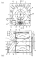
- an electrodynamic transducer head 10 which comprises an electromagnet with a core 12 and a magnetic winding 14 surrounding it.
- the electromagnet has an inner pole piece, generally provided with reference number 16, and associated outer pole pieces 22 and 24, which are assigned to it and are designed as a pair.
- the inner pole piece 16 starts from the core 12 and comprises an end section 18, also referred to as a pole piece head, on which excitation and receiving coils (not shown) are arranged, which in turn is protected against damage by a cap 20. This is necessary because the transducer head 10 is placed directly on a workpiece to be checked in the form of, for example, a metal sheet, a tank bottom or another flat electrically conductive object.
- the protective cap 20 can consist of metal, preferably with a nitrided surface, and have radially extending slots. This is necessary to prevent eddy current formation.
- the protective cap can also have a layer of synthetic stone such as sapphire, which is lowered directly onto the workpiece.
- the end regions 26, 28 of the outer pole shoe pair 22, 24, which are assigned to the inner pole shoe 16 and face the rotationally symmetrical pole shoe head 18, are concave in shape, that is to say have a geometry as can be seen in DE-A-31 23 935.
- the end section 18 of the inner pole piece 16 is located off-center with respect to the central axis 29 of the core 12 of the electromagnet. Furthermore, the core 12 is supported with the inner pole piece 16 and the outer pair of pole pieces 22, 24 via ball bearings 30, 32, 34 in order to carry out a rotary movement without moving the magnetic winding 14.
- This has the advantage that the magnetic winding 14, as a relatively large mass, does not rotate when the inner and outer pole shoes 16, 22, 24 rotate. As a result, no large centrifugal forces are necessary. If the outer and inner pole pieces 22, 24, 16 were now rotated, the track width of the electrodynamic converter according to the invention results from the double distance between the central axis 29 and the pole shoe head 18. Accordingly, a desired track width can be determined by specifying the distance between the central axis 29 Core 12 and the pole piece head 18 are specified.
- the pole shoe head 18 is detachably arranged on a cylinder section 46 of the inner pole shoe 16 and preferably also detachably extends from the outer end face 48 of the core 12.
- the main axis of the cylinder section 46 extends at an angle of 90 ° C ⁇ ⁇ 180 ° to the central axis 29.
- the pole shoe head 18 is then releasably attached to the outer end face 50 of the cylinder section 46.
- the outer pole piece 22, 24 is designed to rotate synchronously with the inner pole piece 16
- the outer pole piece can alternatively be designed as a closed, annular body in plan view, which extends along the circular path of the inner pole piece 16.
- a compensating element 36 is assigned to the angled section 46 of the inner pole piece 16 in order to achieve a mass compensation.
- a further inner pole piece (2nd probe head) can be arranged instead of the compensating element 36, the structure of which corresponds to that of the inner pole piece 16 described at the beginning with pole piece head 18 and cover 20 (1st probe head).
- an outer pair of pole pieces must of course also be assigned to the further inner pole piece, provided that this is to be rotated with the inner pole piece.
- the rotation of the inner pole piece 16 with the core 12 and optionally the outer pole piece 22, 24 can take place via a flange 38 which is connected to the core 12 at the rear of the electromagnet and is set in rotation by means of a toothed belt, for example.
- the signal transmission between the excitation and reception coils takes place via schematically illustrated slip rings 40.
- the outer pair of pole shoes 22, 24 can be supported in the end region of the transducer head 10 relative to the core 12. This can be done via connecting elements 42, 44, which consist of non-ferritic material.
Landscapes
- Physics & Mathematics (AREA)
- Electromagnetism (AREA)
- Health & Medical Sciences (AREA)
- Life Sciences & Earth Sciences (AREA)
- Chemical & Material Sciences (AREA)
- Analytical Chemistry (AREA)
- Biochemistry (AREA)
- General Health & Medical Sciences (AREA)
- General Physics & Mathematics (AREA)
- Immunology (AREA)
- Pathology (AREA)
- Investigating Or Analyzing Materials By The Use Of Magnetic Means (AREA)
- Investigating Or Analyzing Materials By The Use Of Ultrasonic Waves (AREA)
- Transducers For Ultrasonic Waves (AREA)
- Electrostatic, Electromagnetic, Magneto- Strictive, And Variable-Resistance Transducers (AREA)
Description
- Die Erfindung bezieht sich auf einen elektrodynamischen Wandler zur zerstörungsfreien Werkstoffprüfung mittels Ultraschall mit einem Elektromagneten, der einen von einer im Wandler stationär angeordneten Magnetwicklung umgebenen Kern aufweist, mit zumindest einem von dem Kern ausgehenden inneren Polschuh und einem diesem zugeordneten äußeren Polschuh, wobei auf einem einem zu überprürenden, elektrisch leitfähigen Werkstück zugewandten Endabschnitt des inneren Polschuhs Erreger- und Empfangsspulen angeordnet sind.
- Um Bleche, Tankböden oder andere elektrisch leitfähige flächige Gegenstände überprüfen zu können, ist es wünschenswert, Prüfverfahren einzusetzen, bei denen die Anzahl der benötigten Prüfköpfe gering, also eine möglichst große Prüfspurbreite gegeben ist. Um diesen Anforderungen zu genügen, können Wirbelstromsender oder Ultraschallprüfköpfe mit Wasserankopplung benutz werden, wobei die Sonden oszillierend oder auf einer Scheibe rotierend angeordnet werden (Materialprüfung 16 (1974) Nr. 9 September, Seiten 281-282). Allerdings haben Wirbelstromsonden den Nachteil, daß nur oberflächennahe Fehler detektiert werden können. Mit den Wirbelstromsonden können dagegen keine Dimensionsmessungen durchgeführt werden. Ferner sind Wirbelstromsonden unempfindlich gegen die häufig auftretenden Dopplungsfehler. Bei der Verwendung von Piezoprüfköpfen ist eine Ankopplung über eine Wasserstrecke erforderlich, wodurch sich ein rotierendes System nur schwer und aufwendig realisieren läßt. Außerdem ist bei oszillierenden Systemen durch die Oszillationsfrequenz (1 bis 2 Hz) eine hohe Prüfgeschwindigkeit nicht oder nur mit großem Aufwand durch Vervielfachung der Kopfzahl möglich.
- Benutzt man elektrodynamische Wandler der eingangs beschriebenen Art (wie sie zum Beispiel in der DE-OS 31 23 935 oder EP-A2-0045412 beschrieben sind), so kann zwar eine Fehler- und Dickenbestimmung erfolgen, wobei eine Ankopplung über eine Wasserstrecke nicht erforderlich ist. Bei diesen Wandlern ist der innere Polschuh stets rotationssymmetrisch zur Mittelachse des Kerns des Elektromagneten ausgebildet, wobei Erreger- und Empfangsspule auf dem freien Ende des inneren Polschuhs oder seitlich von diesem angeordnet sein können. Aufgrund des großen Gewichtes entsprechender Köpfe sind jedoch große Fliehkräfte bei der Rotation oder große Beschleunigungskräfte bei einer Oszillation notwendig.
- Aufgabe der vorliegenden Erfindung ist es, einen elektrodynamischen Wandler der eingangs beschriebenen Art so auszubilden, daß eine große Spurbreite erzielt werden kann, ohne daß der gesamte Wandler rotieren oder oszillieren muß, so daß weder große Fliehkräfte, noch große Beschleunigungskräfte auftreten.
- Die Aufgabe wird erfindungsgemäß dadurch gelöst, daß der Endabschnitt außermittig in Bezug auf die Mittelachse des Kerns angeordnet und mit dem Kern um dessen Mittelachse drehbar ausgebildet ist. Mit anderen Worten beschreibt der die Erreger- und Empfangsspule aufweisende Endabschnitt des inneren Polschuhs eine koaxial zur Kernachse des Elektromagneten verlaufende Kreisbahn. Durch den Abstand Mittelachse - Endabschnitt wird die Hälfte der gewünschten Spurbreite vorgegeben, so daß durch konstruktiv einfache Maßnahmen erreicht wird, eine große Spurbreite zu erzielen. Dabei erfolgt eine Abstützung zwischen dem Kern und dem von ihm ausgehenden inneren Polschuh über Kugellager, so daß eine reibungsfreie Bewegung möglich ist. Der Antrieb des inneren Kerns selbst kann über einen Riemenantrieb erfolgen.
- Der dem inneren Polschuh zugeordnete äußere Polschuh kann nun entweder synchron mitrotieren oder in Bezug auf die Magnetwicklung stationär ausgebildet sein und sich entlang der Kreisbahn des Endabschnitts erstrecken. In Draufsicht ergibt sich folglich eine Ringgeometrie des äußeren Polschuhs.
- Durch die erfindungsgemäße Lehre wird insbesondere der Vorteil erzielt, daß die Magnetwicklungen als relativ große Masse nicht mitrotieren muß. Dadurch sind Drehzahl von 200-300 rpm möglich. Ferner ist der benötigte Freiraum für die Rotation um den Radius der Magnetwicklung kleiner gegenüber der bislang üblichen Rotation des gesamten Prüfkopfes. Dadurch werden geringere Einbaumaßnahmen erforderlich. Bezüglich der verwendeten Piezoprüfköpfe ergibt sich der Vorteil, daß neben der wesentlich komplexeren Mechanik vor allem ein Kopplungsmedium nicht erforderlich ist.
- In weiterer Ausgestaltung der Erfindung gehen von dem Kern zwei innere vorzugsweise diametral zueinander angeordnete Polschuhe aus, deren Endabschnitte - erfindungsgemäß - außermittig in Bezug auf die Mittelachse des Kerns angeordnet sind. Sofern nur ein innerere Polschuh vorhanden ist, kann diesem ein Ausgleichselement zugeordnet sein, um so einen Massenausgleich vorzunehmen.
- Der innere Polschuh bzw. das Ausgleichselement umfassen nach einer weiteren Ausgestaltung der Erfindung einen von der äußeren Stirnfläche des Kerns ausgehenden und zu dessen Mittelachse abgewinkelten Zylinderabschnitt. Sofern es sich hierbei um den inneren Polschuh handelt, ist auf der äußeren Stirnfläche des Zylinderabschnitts der die Erreger- und Empfangsspule aufweisende als Polschuhkopf ausgebildete Endabschnitt lösbar angeordnet. Dies hat den Vorteil, daß bei einer Beschädigung der Erreger-und Empfangsspule ein problemloser Austausch des Polschuhkopfes, also des Endabschnitts erfolgen kann, ohne daß Änderungen an der Polschuhanordnung selbst erforderlich sind.
- Die Erreger- und Empfangsspulen weisen eine sich in Richtung auf das zu überprüfende Werkstück erstreckende Schutzkappe auf, um Beschädigungen jener weitgehend zu vermeiden. Dabei kann die Schutzkappe aus Metall mit nitrierter Oberfläche bestehen und radial verlaufende Schlitze aufweisen. Alternativ kann die Schutzkappe eine Schicht aus synthetischem Stein wie Saphir aufweisen, die dem Werkstück zugewandt und auf diesem abgestützt wird.
- Die Erfindung wird nachstehend an Hand eines in der Zeichnung dargestellten bevorzugten Ausführungsbeispiels näher erläutert.
- Es zeigen :
- Fig. 1 einen elektrodynamischen Wandler in Draufsicht und
- Fig. 2 eine Schnittdarstellung des Wandlers entlang der Linie II-II.
- In den Figuren ist ein elektrodynamischer Wandlerkopf 10 dargestellt, der einen Elektromagneten mit Kern 12 und diesen umgebender Magnetwicklung 14 umfaßt. Der Elektromagnet weist einen allgemein mit dem Bezugszeichen 16 versehenen inneren Polschuh sowie diesem zugeordnete, als Paar ausgebildete äußere Polschuhe 22 und 24 auf. Der innere Polschuh 16 geht von dem Kern 12 aus und umfaßt einen auch als Polschuhkopf bezeichneten Endabschnitt 18, auf dem nicht dargestellte Erreger- und Empfangsspulen angeordnet sind, die ihrerseits durch eine Kappe 20 gegen Beschädigungen geschützt ist. Dies ist erforderlich, da der Wandlerkopf 10 unmittelbar auf ein zu überprüfendes Werkstück in Form von zum Beispiel einem Blech, einem Tankboden oder einem anderen flächigen elektrisch leitfähigen Gegenstand abgesetzt wird. Die Schutzkappe 20 kann dabei aus Metall, mit vorzugsweise nitrierter Oberfläche bestehen und radial verlaufende Schlitze aufweisen. Dies ist erforderlich, um eine Wirbelstromausbildung zu unterbinden. Alternativ dazu kann die Schutzkappe aber auch eine Schicht aus synthetischem Stein wie Saphir aufweisen, die unmittelbar auf das Werkstück abgesenkt wird.
- Die dem rotationssymmetrisch ausgebildeten Polschuhkopf 18 zugewandten Stirnbereiche 26, 28 des dem inneren Polschuh 16 zugeordneten äußeren Polschuhpaars 22, 24 sind konkav geformt, weisen also in etwa eine Geometrie auf, wie sie der DE-A-31 23 935 zu entnehmen ist.
- Wie durch die Fig. 1 und 2 verdeutlicht werden soll, befindet sich der Endabschnitt 18 des inneren Polschuhs 16 außermittig in Bezug auf die Mittelachse 29 des Kerns 12 des Elektromagneten. Ferner ist der Kern 12 mit dem inneren Polschuh 16 und dem äußeren Polschuhpaar 22, 24 über Kugellager 30, 32, 34 abgestützt, um ohne Bewegung der Magnetwicklung 14 eine Drehbewegung durchzuführen. Daraus ergibt sich der Vorteil, daß die Magnetwicklung 14 als relativ große Masse bei einer Rotation der inneren und äußeren Polschuhe 16, 22, 24 nicht mitdreht. Demzufolge sind auch keine großen Fliehkräfte notwendig. Würden nun die äußeren und der innere Polschuh 22, 24, 16 in eine Drehbewegung versetzt, so ergibt sich die Spurbreite des erfindungsgemäßen elektrodynamischen Wandlers durch den doppelten Abstand zwischen Mittelachse 29 und Polschuhkopf 18. Demzufolge kann eine gewünschte Spurbreite durch Vorgabe des Abstandes Mittelachse 29 des Kerns 12 und dem Polschuhkopf 18 vorgegeben werden.
- Der Polschuhkopf 18 ist lösbar auf einem Zylinderabschnitt 46 des inneren Polschuhs 16 angeordnet und geht von der äußeren Stirnfläche 48 des Kerns 12 vorzugsweise ebenfalls lösbar aus. Die Hauptachse des Zylinderabschnitts 46 verläuft dabei unter einem Winkel mit 90° C < α < 180° zu der Mittelachse 29. Auf der äußeren Stirnfläche 50 des Zylinderabschnitts 46 ist sodann der Polschuhkopf 18 lösbar befestigt.
- Ist im Ausführungsbeispiel der äußere Polschuh 22, 24 synchron mitdrehend mit dem inneren Polschuh 16 ausgebildet, so kann alternativ dazu der äußere Polschuh als geschlossener in Draufsicht ringförmiger Körper ausgebildet sein, der sich entlang der Kreisbahn des inneren Polschuhs 16 erstreckt.
- Wie die Schnittdarstellung gemäß Fig. 2 verdeutlicht, ist dem abgewinkelten Abschnitt 46 des inneren Polschuhs 16 ein Ausgleichselement 36 zugeordnet, um einen Massenausgleich zu erzielen. Gegebenenfalls kann an Stelle des Ausgleichselements 36 ein weiterer innerer Polschuh (2. Sondenkopf) angeordnet werden, dessen Aufbau dem des eingangs beschriebenen inneren Polschuhs 16 mit Polschuhkopf 18 und Abdeckung 20 (1. Sondenkopf) entspricht. In diesem Fall muß selbstverständlich dem weiteren inneren Polschuh ebenfalls ein äußeres Polschuhpaar zugeordnet werden, sofern dieses mit dem inneren Polschuh mitgedreht werden soll.
- Die Rotation des inneren Polschuhs 16 mit Kern 12 und gegebenenfalls äußerem Polschuh 22, 24 kann über einen Flansch 38 erfolgen, der an der Rückseite des Elektromagneten mit dem Kern 12 verbunden ist und über zum Beispiel einen Zahnriemen in Drehbewegung versetzt wird. Die Signalübertragung zwischen der Erreger- und Empfangsspule erfolgt über schematisch dargestellte Schleifringe 40. Auch sei darauf hingewiesen, daß das äußere Polschuhpaar 22, 24 im Stirnbereich des Wandlerkopfs 10 gegenüber dem Kern 12 abgestützt sein kann. Dies kann über Verbindungselemente 42, 44 erfolgen, die aus nichtferritischem Material bestehen.
Claims (8)
Applications Claiming Priority (2)
| Application Number | Priority Date | Filing Date | Title |
|---|---|---|---|
| DE3425386 | 1984-07-10 | ||
| DE3425386A DE3425386C1 (de) | 1984-07-10 | 1984-07-10 | Elektrodynamischer Wandler |
Publications (3)
| Publication Number | Publication Date |
|---|---|
| EP0168011A2 EP0168011A2 (de) | 1986-01-15 |
| EP0168011A3 EP0168011A3 (en) | 1988-07-13 |
| EP0168011B1 true EP0168011B1 (de) | 1990-01-24 |
Family
ID=6240279
Family Applications (1)
| Application Number | Title | Priority Date | Filing Date |
|---|---|---|---|
| EP85108441A Expired - Lifetime EP0168011B1 (de) | 1984-07-10 | 1985-07-08 | Elektrodynamischer Wandler |
Country Status (4)
| Country | Link |
|---|---|
| US (1) | US4665752A (de) |
| EP (1) | EP0168011B1 (de) |
| JP (1) | JPS6135352A (de) |
| DE (2) | DE3425386C1 (de) |
Families Citing this family (14)
| Publication number | Priority date | Publication date | Assignee | Title |
|---|---|---|---|---|
| DE3834248A1 (de) * | 1988-10-05 | 1990-04-12 | Mannesmann Ag | Elektrodynamischer wandlerkopf |
| DE4002100A1 (de) * | 1990-01-25 | 1991-08-08 | Nukem Gmbh | Elektrodynamischer wandlerkopf |
| US5237874A (en) * | 1991-10-07 | 1993-08-24 | The Babcock & Wilcox Company | Rotating electromagnetic acoustic transducer for metal inspection |
| US5446382A (en) * | 1993-06-23 | 1995-08-29 | The Babcock & Wilcox Company | Eddy current probe having one yoke within another yoke for increased inspection depth, sensitivity and discrimination |
| US20010042702A1 (en) * | 2000-04-17 | 2001-11-22 | Stuntz Gordon F. | Cycle oil conversion process |
| US20040066008A1 (en) * | 2002-10-04 | 2004-04-08 | Smith Robert C. | Introducer seal assembly |
| GB0314357D0 (en) * | 2003-06-19 | 2003-07-23 | Pii Ltd | Electromagnetic acoustic transducer |
| US7608082B2 (en) * | 2005-01-06 | 2009-10-27 | Tyco Healthcare Group Lp | Surgical seal for use in a surgical access apparatus |
| US7546770B2 (en) * | 2006-01-05 | 2009-06-16 | General Electric Company | Electromagnetic acoustic transducer |
| US8932275B2 (en) * | 2006-07-07 | 2015-01-13 | Covidien Lp | Surgical seal assembly |
| US7886604B2 (en) * | 2007-01-26 | 2011-02-15 | Idemitsu Kosan Co., Ltd. | Electromagnetic ultrasonic flaw detection method and electromagnetic ultrasonic transducer to be used therefor |
| US20090105635A1 (en) * | 2007-10-17 | 2009-04-23 | Tyco Healthcare Group Lp | Access assembly with seal lubricant mechanism |
| JP5049821B2 (ja) * | 2008-02-29 | 2012-10-17 | 日立オートモティブシステムズ株式会社 | エンジン始動用スタータ |
| US9028448B2 (en) * | 2008-06-19 | 2015-05-12 | Covidien Lp | Access seal with interstitial channels |
Family Cites Families (5)
| Publication number | Priority date | Publication date | Assignee | Title |
|---|---|---|---|---|
| DE3029036A1 (de) * | 1980-07-31 | 1982-03-04 | Mannesmann AG, 4000 Düsseldorf | Vorrichtung zur pruefung von werkstoffen |
| DE3123935C2 (de) * | 1981-06-16 | 1985-03-28 | Nukem Gmbh, 6450 Hanau | Elektrodynamischer Wandler |
| US4398425A (en) * | 1981-08-03 | 1983-08-16 | Dymax Corporation | Ultrasonic scanning transducer |
| AT379071B (de) * | 1982-07-19 | 1985-11-11 | Kretztechnik Gmbh | Schnittbildmechanik fuer ein ultraschallschnittbildgeraet |
| DE3414071C1 (de) * | 1984-04-13 | 1985-04-11 | Nukem Gmbh, 6450 Hanau | Elektrodynamischer Wandler |
-
1984
- 1984-07-10 DE DE3425386A patent/DE3425386C1/de not_active Expired
-
1985
- 1985-06-27 US US06/749,566 patent/US4665752A/en not_active Expired - Fee Related
- 1985-07-08 DE DE8585108441T patent/DE3575609D1/de not_active Expired - Fee Related
- 1985-07-08 EP EP85108441A patent/EP0168011B1/de not_active Expired - Lifetime
- 1985-07-10 JP JP15212085A patent/JPS6135352A/ja active Pending
Also Published As
| Publication number | Publication date |
|---|---|
| EP0168011A2 (de) | 1986-01-15 |
| DE3575609D1 (de) | 1990-03-01 |
| JPS6135352A (ja) | 1986-02-19 |
| US4665752A (en) | 1987-05-19 |
| EP0168011A3 (en) | 1988-07-13 |
| DE3425386C1 (de) | 1985-11-14 |
Similar Documents
| Publication | Publication Date | Title |
|---|---|---|
| DE3425386C1 (de) | Elektrodynamischer Wandler | |
| EP0413119B1 (de) | Mittenfreies Grosswälzlager | |
| DE4219318C2 (de) | Verfahren und Vorrichtung zum Bestimmen des Kontaktwinkels von Kugellagern | |
| DE3905430C2 (de) | ||
| DE3401072C2 (de) | Elektrodynamischer Wandlerkopf | |
| DE2509927C3 (de) | Wirbelstromprüf spulenanordnung | |
| DE19720233B4 (de) | Verfahren und Gerät zum Schleifen einer schrägen Fläche | |
| DE3836540C2 (de) | ||
| DE2106891B2 (de) | Antriebsvorrichtung fuer kugeln zu deren zerstoerungsfreien pruefung | |
| DE7710169U1 (de) | Vorrichtung zum abdichten des keilriemens und der riemenscheiben bei plattenruettlern | |
| EP0304394A2 (de) | Verfahren zur Feststellung von Rissen in einer Welle mittels Ultraschall-Impulsechoverfahren und Vorrichtung zu seiner Durchführung | |
| DE69800277T2 (de) | Vorrichtung und Verfahren zur Messung der Spannung eines Kolbenrings | |
| DE3206503C1 (de) | Verfahren zur Kompensation der bei der Drehmomentmessung nach dem Wirbelstromprinzip an Wellen auftretenden durch die Inhomogenität der Permeabilität der Oberfläche der Welle erzeugten elektr. Störspannung | |
| DE3414362A1 (de) | Verfahren zur ultraschall-pruefung von bolzen mit einem wanddickensprung | |
| DE9415885U1 (de) | Ultraschallwandler zur Prüfung von Eisenbahnrädern | |
| DE1424430B2 (de) | Magnetplattenspeicher | |
| EP0038055A2 (de) | Ultraschallprüfverfahren | |
| DE1187041B (de) | Vorrichtung zum Messen der Radialkraft von Wellendichtringen | |
| DE3211425C2 (de) | ||
| DE2138289C3 (de) | Vorrichtung zum Bestimmen der Rauheit sich bewegender Oberflächen eines Werkstücks | |
| EP0158352A2 (de) | Elektrodynamischer Wandler | |
| DE112010004300T5 (de) | Vorrichtung zur Ausrichtung einer Rundlaufabweichungsmessvorrichtung | |
| DE3448080A1 (de) | Elektrodynamischer wandler | |
| DE2742326C2 (de) | Einrichtung zur Ermittlung von Oberflächenfehlern o.dgl. auf Kugeln | |
| DE2452368A1 (de) | Verfahren und vorrichtung zur bestimmung von undichtigkeiten von kernreaktor-brennelementen |
Legal Events
| Date | Code | Title | Description |
|---|---|---|---|
| PUAI | Public reference made under article 153(3) epc to a published international application that has entered the european phase |
Free format text: ORIGINAL CODE: 0009012 |
|
| AK | Designated contracting states |
Designated state(s): DE FR GB |
|
| PUAL | Search report despatched |
Free format text: ORIGINAL CODE: 0009013 |
|
| AK | Designated contracting states |
Kind code of ref document: A3 Designated state(s): DE FR GB |
|
| 17P | Request for examination filed |
Effective date: 19880620 |
|
| 17Q | First examination report despatched |
Effective date: 19890606 |
|
| GRAA | (expected) grant |
Free format text: ORIGINAL CODE: 0009210 |
|
| AK | Designated contracting states |
Kind code of ref document: B1 Designated state(s): DE FR GB |
|
| REF | Corresponds to: |
Ref document number: 3575609 Country of ref document: DE Date of ref document: 19900301 |
|
| GBT | Gb: translation of ep patent filed (gb section 77(6)(a)/1977) | ||
| ET | Fr: translation filed | ||
| PG25 | Lapsed in a contracting state [announced via postgrant information from national office to epo] |
Ref country code: GB Effective date: 19900708 |
|
| PLBE | No opposition filed within time limit |
Free format text: ORIGINAL CODE: 0009261 |
|
| STAA | Information on the status of an ep patent application or granted ep patent |
Free format text: STATUS: NO OPPOSITION FILED WITHIN TIME LIMIT |
|
| 26N | No opposition filed | ||
| GBPC | Gb: european patent ceased through non-payment of renewal fee | ||
| PG25 | Lapsed in a contracting state [announced via postgrant information from national office to epo] |
Ref country code: FR Effective date: 19910329 |
|
| PG25 | Lapsed in a contracting state [announced via postgrant information from national office to epo] |
Ref country code: DE Effective date: 19910403 |
|
| REG | Reference to a national code |
Ref country code: FR Ref legal event code: ST |