EP0167500A2 - A support frame for an awning having a one-piece fabric cover - Google Patents
A support frame for an awning having a one-piece fabric cover Download PDFInfo
- Publication number
- EP0167500A2 EP0167500A2 EP85830169A EP85830169A EP0167500A2 EP 0167500 A2 EP0167500 A2 EP 0167500A2 EP 85830169 A EP85830169 A EP 85830169A EP 85830169 A EP85830169 A EP 85830169A EP 0167500 A2 EP0167500 A2 EP 0167500A2
- Authority
- EP
- European Patent Office
- Prior art keywords
- awning
- guides
- support frame
- support
- fact
- Prior art date
- Legal status (The legal status is an assumption and is not a legal conclusion. Google has not performed a legal analysis and makes no representation as to the accuracy of the status listed.)
- Granted
Links
- 239000004744 fabric Substances 0.000 title claims abstract description 23
- 239000000969 carrier Substances 0.000 claims description 4
- 238000006073 displacement reaction Methods 0.000 abstract description 2
- 230000002860 competitive effect Effects 0.000 description 1
- 238000010276 construction Methods 0.000 description 1
- 230000008878 coupling Effects 0.000 description 1
- 238000010168 coupling process Methods 0.000 description 1
- 238000005859 coupling reaction Methods 0.000 description 1
- 230000000694 effects Effects 0.000 description 1
- 238000009434 installation Methods 0.000 description 1
- 230000004048 modification Effects 0.000 description 1
- 238000012986 modification Methods 0.000 description 1
- 238000009877 rendering Methods 0.000 description 1
Images

Classifications
-
- E—FIXED CONSTRUCTIONS
- E06—DOORS, WINDOWS, SHUTTERS, OR ROLLER BLINDS IN GENERAL; LADDERS
- E06B—FIXED OR MOVABLE CLOSURES FOR OPENINGS IN BUILDINGS, VEHICLES, FENCES OR LIKE ENCLOSURES IN GENERAL, e.g. DOORS, WINDOWS, BLINDS, GATES
- E06B9/00—Screening or protective devices for wall or similar openings, with or without operating or securing mechanisms; Closures of similar construction
- E06B9/24—Screens or other constructions affording protection against light, especially against sunshine; Similar screens for privacy or appearance; Slat blinds
- E06B9/40—Roller blinds
-
- E—FIXED CONSTRUCTIONS
- E04—BUILDING
- E04F—FINISHING WORK ON BUILDINGS, e.g. STAIRS, FLOORS
- E04F10/00—Sunshades, e.g. Florentine blinds or jalousies; Outside screens; Awnings or baldachins
- E04F10/02—Sunshades, e.g. Florentine blinds or jalousies; Outside screens; Awnings or baldachins of flexible canopy materials, e.g. canvas ; Baldachins
- E04F10/06—Sunshades, e.g. Florentine blinds or jalousies; Outside screens; Awnings or baldachins of flexible canopy materials, e.g. canvas ; Baldachins comprising a roller-blind with means for holding the end away from a building
- E04F10/0607—Sunshades, e.g. Florentine blinds or jalousies; Outside screens; Awnings or baldachins of flexible canopy materials, e.g. canvas ; Baldachins comprising a roller-blind with means for holding the end away from a building with guiding-sections for supporting the movable end of the blind
-
- E—FIXED CONSTRUCTIONS
- E04—BUILDING
- E04F—FINISHING WORK ON BUILDINGS, e.g. STAIRS, FLOORS
- E04F10/00—Sunshades, e.g. Florentine blinds or jalousies; Outside screens; Awnings or baldachins
- E04F10/02—Sunshades, e.g. Florentine blinds or jalousies; Outside screens; Awnings or baldachins of flexible canopy materials, e.g. canvas ; Baldachins
- E04F10/06—Sunshades, e.g. Florentine blinds or jalousies; Outside screens; Awnings or baldachins of flexible canopy materials, e.g. canvas ; Baldachins comprising a roller-blind with means for holding the end away from a building
- E04F10/0666—Accessories
- E04F10/067—Accessories acting as intermediate support of the flexible canopy
-
- E—FIXED CONSTRUCTIONS
- E04—BUILDING
- E04F—FINISHING WORK ON BUILDINGS, e.g. STAIRS, FLOORS
- E04F10/00—Sunshades, e.g. Florentine blinds or jalousies; Outside screens; Awnings or baldachins
- E04F10/02—Sunshades, e.g. Florentine blinds or jalousies; Outside screens; Awnings or baldachins of flexible canopy materials, e.g. canvas ; Baldachins
- E04F10/06—Sunshades, e.g. Florentine blinds or jalousies; Outside screens; Awnings or baldachins of flexible canopy materials, e.g. canvas ; Baldachins comprising a roller-blind with means for holding the end away from a building
- E04F10/0666—Accessories
- E04F10/0677—Accessories acting as centre bearing
-
- F—MECHANICAL ENGINEERING; LIGHTING; HEATING; WEAPONS; BLASTING
- F16—ENGINEERING ELEMENTS AND UNITS; GENERAL MEASURES FOR PRODUCING AND MAINTAINING EFFECTIVE FUNCTIONING OF MACHINES OR INSTALLATIONS; THERMAL INSULATION IN GENERAL
- F16B—DEVICES FOR FASTENING OR SECURING CONSTRUCTIONAL ELEMENTS OR MACHINE PARTS TOGETHER, e.g. NAILS, BOLTS, CIRCLIPS, CLAMPS, CLIPS OR WEDGES; JOINTS OR JOINTING
- F16B2200/00—Constructional details of connections not covered for in other groups of this subclass
- F16B2200/67—Rigid angle couplings
-
- Y—GENERAL TAGGING OF NEW TECHNOLOGICAL DEVELOPMENTS; GENERAL TAGGING OF CROSS-SECTIONAL TECHNOLOGIES SPANNING OVER SEVERAL SECTIONS OF THE IPC; TECHNICAL SUBJECTS COVERED BY FORMER USPC CROSS-REFERENCE ART COLLECTIONS [XRACs] AND DIGESTS
- Y10—TECHNICAL SUBJECTS COVERED BY FORMER USPC
- Y10T—TECHNICAL SUBJECTS COVERED BY FORMER US CLASSIFICATION
- Y10T403/00—Joints and connections
- Y10T403/32—Articulated members
- Y10T403/32254—Lockable at fixed position
- Y10T403/32262—At selected angle
- Y10T403/32319—At selected angle including pivot stud
Definitions
- the present invention relates generally to a support frame for an awning, and particularly a support frame for a wide awning having a one-piece fabric cover.
- awnings or curtains generally utilised for the covering of balconies or other open spaces, are generally constituted by a plurality of guides on which the awning fabric or covering is supported, the awning fabric being connected to a draw bar supported by carriages slidable on suitable guides.
- Another disadvantage is constituted by the fact that in situations where it is required to have very wide covers, it is necessary at present to utilise awnings constituted by several separate fabric sheets, disposed alongside one another, with the disadvantage of inevitably having a zone, even if only narrow, which remains open between the adjacent edges of two contiguous fabric pieces, thus making it necessary to provide cover strips or other covering elements to close the otherwise open zones.
- a further disadvantage is constituted by the fact that in the case in which curves on the guides must be provided, the point of curvature is generally a very critical point, which is currently formed by utilising fixed curves which do not offer the possibility of continuously varying the mutual inclination of the guides connected to the curves.
- the present invention seeks to overcome the previously mentioned disadvantages by providing a support frame for an awning which allows a fabric cover made in only one piece to be employed, even if the frame has several spans, thereby avoiding the occurrence of gaps between adjacent awning cover pieces and having the possibility of extending or retracting the awning cover with only a single operating action.
- a particular advantage of the invention is that it provides a support frame for an awning, which permits the guides to be accurately positioned regardless of whether the frame is connected to the ceiling or the walls, and despite any irregularities in the fixings, thereby making the mounting of the frame considerably simpler and quicker than has hithertofore been the case.
- a further advantage of the present invention is that it provides a supporting frame which can be used equally well whether or not the awning cover movement is motorised, in that the guides which are used are already provided with means for the introduction of the necessary components for performing a motorised awning drawing operation.
- Another advantage of the present invention is that it provides a support frame including a curved guide track portion the, curvature of which is adjustable in a simple manner thereby offering the possibility of easily adapting it to all the possible configurations which may be encountered upon installation.
- a support frame for an awning having a one-piece awning cover is characterised by the fact that it comprises brackets for attachment to a support structure, which brackets support a square bar on which are positioned attachment carriers mounted at the ends of guides on which are slidable carriages for drawing a bar to which one end of an awning cover can be attached, the bar lying above the said guides over the whole of its longitudinal length to allow the use of a one-piece awning fabric, even if the frame has several spans; this awning fabric, at its other end, being wound on a wind-up roller rotatably supported by arms connected to the square bar.
- the said draw bar lies above the guides, along the whole of its length, thus allowing utilisation of a one-piece awning, even if the frame has several spans.
- a further advantage of the present invention is that it provides a support frame which, as well as being easily obtainable starting from elements which are readily commercially available, is of very low cost thereby making it commercially competitive.
- the support frame for wide awnings having a one-piece fabric comprises mounting brackets 1 which can be fitted to the support structure which may be a wall or a ceiling. To the brackets 1 there is connected a square bar which extends substantially the whole of the width of the awning to be fitted.
- each guide 4 has a substantially rectangular body the upper and lower faces of which are formed with channels, indicated 5 and 6, for the sliding of possible drive belts for motorising the opening and closing movements or raising and lowering movements of the awning.
- slidable carriages 10 On the guides 4 are slidable carriages 10 which are provided with rollers 11 which engage within the recesses 7. At their top the carriages 10 support an awning draw bar 12 which is connected to the end of the awning fabric, generally indicated with the reference numeral 13.
- the described coupling of the carriages and the draw bar 12 is such that the bar 12 is always spaced from and above the guides 4 so that it is possible to utilise a single draw bar and, consequently, an awning cover or curtain 13 made from a single piece of fabric, even if the frame has several spans.
- the awning cover 13 at its other end, is connected to a wind-up roller 14 which is rotatably supported by support arms 15 which are connected to the square bar 2 by means of a grooved hole 16 (splined) which gives the possibility of adjusting their inclination at will and, consequently, varying the position of the wind up roller 14.
- the frame is completed by the presence of support rollers 17 which extend transversely of the guides 4 between the various spans, which are connected to the lateral grooves 8 in the guides and which serve the function of supporting the awning fabric to prevent undue bulges or unwanted displacements when it is windy.
- supports 19, which are connected to the square bar 2 and which engage the outer surface of the curtain wind-up roller 14 to prevent it from flexing.
- the guides 4 are provided with curves, generally indicated with the reference numeral 20, which have the important characteristic that their inclination is continuously adjustable, so that they perfectly join the line of the guides 4 without creating any element of interruption thereby.
- the guide connectors 21 are themselves connected, at the endsopposite those where they join the guides 4, to a pair of sectors 22, which extend around a portion of a circumference and which retain between them a curved continuity plate 23 which serves the function of creating a structural continuity independently of the mutual inclination between the two connecters 21, constituting the curves.
- the sectors 22 create, on their outer periphery, a continuity for the guide channel 5 and, internally, have projecting spindles 26, with pulleys 27, which serve as guide and slide elements for the possible drive belts which slide in the lower channel 6 of the guides 4.
- first side plate 30 provided with a circular protuberance 31, which is super-imposed over the sectors 22, and, by a second 'side plate 32 the end of which is shaped with an arcuate curve 33 which is concentric with the circular curve of the protuberance 31.
- the side plates 30 and 32 have through holes indicated 40 for receiving fixing screws which can be inserted into a connection plate which can be introduced into the interior of the grooves 8 in the guides 4.
- the side plates 30 and 32 are symmetrically disposed on both sides of the guides 4 in such a way that it is possible to make the entire curve with a reduced number of component elements in that the curve itself is made with symmetrical elements.
- a clamping bolt 50 is provided, which in practice constitutes the axis of rotation of the curve and which joins together the side plates 30 and 32 and the sectors 22 of the curve.
- an element 60 which can be fixed on the curve, and which is provided with a pair of radially extending . arms 61 which carry the support rollers 17.
- the element 60 is provided with circumferential slots 62 which allow it to be positioned in any angular orientation to obtain the best positioning of the fixing element 60 itself.
- the presence of the curve gives the possibility of varying the relative inclinations of adjacent sections of the guide 4 at will within wide margins without requiring any particular modifications in that the curve is able to create a structural continuity for the passage of the carriage 10 as well as for the belts moveable in the channels 5 and 6 so as to be able to effect motorisation of the drawing of the awning.
- the structure utilised gives the possibility of employing a one-piece awning fabric even if the support frame has several spans. It is important also to emphasise that the structural realisation of the curve allows a continuous variation of the relative angle between the guides without creating any structural discontinuity.
- the embodiment of the invention described hereinabove by way of example can; of course, be replaced by any technically equivalent elements without departing from the scope of the invention defined hereinbelow.
Abstract
Description
- The present invention relates generally to a support frame for an awning, and particularly a support frame for a wide awning having a one-piece fabric cover.
- As is known, awnings or curtains generally utilised for the covering of balconies or other open spaces, are generally constituted by a plurality of guides on which the awning fabric or covering is supported, the awning fabric being connected to a draw bar supported by carriages slidable on suitable guides.
- In the known constructions the guides are directly fixed to the walls or the ceiling thus creating difficulties in the accurate positioning of these whenever irregularities in the walls are encountered, and very often difficulties are met in fixing the guides at this point.
- Another disadvantage is constituted by the fact that in situations where it is required to have very wide covers, it is necessary at present to utilise awnings constituted by several separate fabric sheets, disposed alongside one another, with the disadvantage of inevitably having a zone, even if only narrow, which remains open between the adjacent edges of two contiguous fabric pieces, thus making it necessary to provide cover strips or other covering elements to close the otherwise open zones.
- In awnings of the known type considerable difficulties are encountered in motorising the curtain since in many cases suitable guides for allowing motorising of the curtains are not already provided or installed.
- A further disadvantage is constituted by the fact that in the case in which curves on the guides must be provided, the point of curvature is generally a very critical point, which is currently formed by utilising fixed curves which do not offer the possibility of continuously varying the mutual inclination of the guides connected to the curves.
- The present invention seeks to overcome the previously mentioned disadvantages by providing a support frame for an awning which allows a fabric cover made in only one piece to be employed, even if the frame has several spans, thereby avoiding the occurrence of gaps between adjacent awning cover pieces and having the possibility of extending or retracting the awning cover with only a single operating action.
- A particular advantage of the invention is that it provides a support frame for an awning, which permits the guides to be accurately positioned regardless of whether the frame is connected to the ceiling or the walls, and despite any irregularities in the fixings, thereby making the mounting of the frame considerably simpler and quicker than has hithertofore been the case.
- A further advantage of the present invention is that it provides a supporting frame which can be used equally well whether or not the awning cover movement is motorised, in that the guides which are used are already provided with means for the introduction of the necessary components for performing a motorised awning drawing operation.
- Another advantage of the present invention is that it provides a support frame including a curved guide track portion the, curvature of which is adjustable in a simple manner thereby offering the possibility of easily adapting it to all the possible configurations which may be encountered upon installation.
- According to the present invention a support frame for an awning having a one-piece awning cover is characterised by the fact that it comprises brackets for attachment to a support structure, which brackets support a square bar on which are positioned attachment carriers mounted at the ends of guides on which are slidable carriages for drawing a bar to which one end of an awning cover can be attached, the bar lying above the said guides over the whole of its longitudinal length to allow the use of a one-piece awning fabric, even if the frame has several spans; this awning fabric, at its other end, being wound on a wind-up roller rotatably supported by arms connected to the square bar.
- The said draw bar lies above the guides, along the whole of its length, thus allowing utilisation of a one-piece awning, even if the frame has several spans.
- A further advantage of the present invention is that it provides a support frame which, as well as being easily obtainable starting from elements which are readily commercially available, is of very low cost thereby making it commercially competitive.
- One embodiment of the present invention will now be more particularly described, by way of example, with reference to the accompanying drawings, in which:
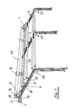
- Figure 1 is a schematic perspective view illustrating the awning support frame of the invention;
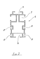
- Figure 2 is a cross section illustrating the shape of the guides; and
- Figure 3 is an exploded perspective view on a larger scale illustrating the component elements' of the curves which can be fitted to the guides.
- Referring now to the drawings, the support frame for wide awnings having a one-piece fabric, according to the invention, comprises mounting brackets 1 which can be fitted to the support structure which may be a wall or a ceiling. To the brackets 1 there is connected a square bar which extends substantially the whole of the width of the awning to be fitted.
- On the
square bar 2 there are fitted a number of guide carrier's 3 (in Figure 1 three such carriers are shown) which are pivotally connected to the upper end of respective guides generally indicated 4. The pivotal connection between theguides 4 and thecarriers 3 which, are supported by the square bar, offers the possibility of rendering the positioning of.the guides themselves independent of the support elements for fixing to the walls or the ceiling, which is the opposite of the situation in the prior art. Eachguide 4, as is clearer in Figure 2, has a substantially rectangular body the upper and lower faces of which are formed with channels, indicated 5 and 6, for the sliding of possible drive belts for motorising the opening and closing movements or raising and lowering movements of the awning. - In the upper part there are further provided opposite
lateral recesses 7 for the sliding of carriages which will be described in more detail hereinbelow, and in the lower part there are providedgrooves 8 for the connection of fixing means which, again, will be described in more detail below. - On the
guides 4 areslidable carriages 10 which are provided withrollers 11 which engage within therecesses 7. At their top thecarriages 10 support anawning draw bar 12 which is connected to the end of the awning fabric, generally indicated with thereference numeral 13. - The described coupling of the carriages and the
draw bar 12 is such that thebar 12 is always spaced from and above theguides 4 so that it is possible to utilise a single draw bar and, consequently, an awning cover orcurtain 13 made from a single piece of fabric, even if the frame has several spans. - The
awning cover 13, at its other end, is connected to a wind-uproller 14 which is rotatably supported bysupport arms 15 which are connected to thesquare bar 2 by means of a grooved hole 16 (splined) which gives the possibility of adjusting their inclination at will and, consequently, varying the position of the wind uproller 14. - The frame is completed by the presence of
support rollers 17 which extend transversely of theguides 4 between the various spans, which are connected to thelateral grooves 8 in the guides and which serve the function of supporting the awning fabric to prevent undue bulges or unwanted displacements when it is windy. - Further, there are provided
supports 19, which are connected to thesquare bar 2 and which engage the outer surface of the curtain wind-uproller 14 to prevent it from flexing. - The
guides 4 are provided with curves, generally indicated with thereference numeral 20, which have the important characteristic that their inclination is continuously adjustable, so that they perfectly join the line of theguides 4 without creating any element of interruption thereby. Thecurves 20, as will be seen in Figure 3, which is an exploded view of a curve, have a pair of guide connectors indicated 21, which can be inserted into the interior of the section constituting theguide 4, and which have the same external profile shape so that they constitute a smooth continuation both for thechannels 5 and 6 for the drive belts, and for thelateral cavities 7 for sliding of therollers 11 of the carriage which supports the awningfabric draw bar 12. - The
guide connectors 21 are themselves connected, at the endsopposite those where they join theguides 4, to a pair ofsectors 22, which extend around a portion of a circumference and which retain between them acurved continuity plate 23 which serves the function of creating a structural continuity independently of the mutual inclination between the twoconnecters 21, constituting the curves. - The
sectors 22 create, on their outer periphery, a continuity for theguide channel 5 and, internally, have projectingspindles 26, withpulleys 27, which serve as guide and slide elements for the possible drive belts which slide in the lower channel 6 of theguides 4. - The elements described above are joined at each side by a
first side plate 30 provided with acircular protuberance 31, which is super-imposed over thesectors 22, and, by a second 'side plate 32 the end of which is shaped with anarcuate curve 33 which is concentric with the circular curve of theprotuberance 31. - The
side plates grooves 8 in theguides 4. - The
side plates guides 4 in such a way that it is possible to make the entire curve with a reduced number of component elements in that the curve itself is made with symmetrical elements. Moreover, a clamping bolt 50 is provided, which in practice constitutes the axis of rotation of the curve and which joins together theside plates sectors 22 of the curve. - Further, an
element 60 is provided which can be fixed on the curve, and which is provided with a pair of radially extending .arms 61 which carry thesupport rollers 17. Theelement 60 is provided withcircumferential slots 62 which allow it to be positioned in any angular orientation to obtain the best positioning of thefixing element 60 itself. - The presence of the curve gives the possibility of varying the relative inclinations of adjacent sections of the
guide 4 at will within wide margins without requiring any particular modifications in that the curve is able to create a structural continuity for the passage of thecarriage 10 as well as for the belts moveable in thechannels 5 and 6 so as to be able to effect motorisation of the drawing of the awning. - From what has been described above it will therefore be seen how the inventionimpreves .on the prior art and, in particular, it is to be emphasised that new criteria for the fixing of the guides to the supporting structure are introduced by utilising the square bar which makes the positioning of the guides independent of the fixing point.
- Moreover, the structure utilised gives the possibility of employing a one-piece awning fabric even if the support frame has several spans. It is important also to emphasise that the structural realisation of the curve allows a continuous variation of the relative angle between the guides without creating any structural discontinuity. The embodiment of the invention described hereinabove by way of example can; of course, be replaced by any technically equivalent elements without departing from the scope of the invention defined hereinbelow.
Claims (10)
Priority Applications (1)
| Application Number | Priority Date | Filing Date | Title |
|---|---|---|---|
| AT85830169T ATE42598T1 (en) | 1984-07-03 | 1985-07-03 | SUPPORT FRAME FOR PARASOL WITH CLOTH IN ONE PIECE. |
Applications Claiming Priority (2)
| Application Number | Priority Date | Filing Date | Title |
|---|---|---|---|
| IT2173684 | 1984-07-03 | ||
| IT21736/84A IT1174229B (en) | 1984-07-03 | 1984-07-03 | SUPPORT FRAME FOR LARGE COVER AWNINGS WITH A SINGLE COVER |
Publications (3)
| Publication Number | Publication Date |
|---|---|
| EP0167500A2 true EP0167500A2 (en) | 1986-01-08 |
| EP0167500A3 EP0167500A3 (en) | 1987-03-18 |
| EP0167500B1 EP0167500B1 (en) | 1989-04-26 |
Family
ID=11186144
Family Applications (1)
| Application Number | Title | Priority Date | Filing Date |
|---|---|---|---|
| EP85830169A Expired EP0167500B1 (en) | 1984-07-03 | 1985-07-03 | A support frame for an awning having a one-piece fabric cover |
Country Status (7)
| Country | Link |
|---|---|
| US (1) | US4655010A (en) |
| EP (1) | EP0167500B1 (en) |
| AT (1) | ATE42598T1 (en) |
| CA (1) | CA1260820A (en) |
| DE (1) | DE3569772D1 (en) |
| ES (1) | ES287763Y (en) |
| IT (1) | IT1174229B (en) |
Cited By (9)
| Publication number | Priority date | Publication date | Assignee | Title |
|---|---|---|---|---|
| EP0219773A2 (en) * | 1985-10-11 | 1987-04-29 | United Industries Holding S.A. | Sun-protecting device |
| EP0322534A1 (en) * | 1987-12-31 | 1989-07-05 | Clauss Markisen | Inclined awning |
| EP0608720A1 (en) * | 1993-01-28 | 1994-08-03 | LOSBERGER SONNENSCHUTZ GmbH & Co. | Adjustable arcuate deviation for awning and shading installation |
| EP0609487A1 (en) * | 1993-01-20 | 1994-08-10 | CLAUSS MARKISEN PROJEKT GmbH | Awning with tensioning means |
| US5615725A (en) * | 1995-12-14 | 1997-04-01 | Formosa Saint Jose Corp. | Outdoor sun shade |
| FR2779475A1 (en) * | 1996-11-13 | 1999-12-10 | Farnier Et Penin Snc | Curved roller blind |
| EP2011932A1 (en) * | 2007-07-06 | 2009-01-07 | Corradi S.r.l. | Unity for conveying rainwater in awnings, pergolas and the like |
| EP2369123A1 (en) * | 2010-03-26 | 2011-09-28 | Shih-Ming Lin | Window blind assembly |
| CN108374528A (en) * | 2017-01-30 | 2018-08-07 | 劳伦斯·德鲁蒙德·麦基奇尼 | Improved shelter |
Families Citing this family (24)
| Publication number | Priority date | Publication date | Assignee | Title |
|---|---|---|---|---|
| USRE33216E (en) * | 1984-07-06 | 1990-05-15 | Blind assembly | |
| FR2587405B1 (en) * | 1985-09-17 | 1988-01-08 | Fouquet Jean Michel | DEVICE FOR SUPPORTING MOBILE COVER ELEMENTS |
| DE3546093A1 (en) * | 1985-12-24 | 1987-07-02 | Hassinger Gmbh Co Kg | DRIVE DEVICE FOR MOVABLE FABRIC COVERS |
| US5010940A (en) * | 1989-01-23 | 1991-04-30 | Norbert Marocco | Swingable junction for a window covering |
| CH681383A5 (en) * | 1990-04-11 | 1993-03-15 | Alusuisse Lonza Services Ag | |
| US5259432A (en) * | 1991-11-29 | 1993-11-09 | Remo C. Danieli | Support frame for moveable awning |
| US5186231A (en) * | 1992-05-01 | 1993-02-16 | Milburn Lewis | Tarpaulin deployment and retraction apparatus |
| US5794679A (en) * | 1997-01-15 | 1998-08-18 | Marvingardens, Ltd. | Canopy structure for sun shade |
| WO2000009831A1 (en) * | 1998-08-17 | 2000-02-24 | Certainteed Shade Systems, L.L.C. | Shade canopy |
| NL1013592C2 (en) * | 1999-11-17 | 2001-05-18 | Aluminium Donk B V | Guide arrangement for roller blind type sun shade, has length guides separated by intermediate guide sections comprising telescopic curved parts |
| AU2003258725A1 (en) * | 2003-08-01 | 2005-03-07 | Llaza, Sa | Arm element for awnings and articulated arm for awnings |
| US20080142064A1 (en) * | 2004-05-14 | 2008-06-19 | Chrisi Maraki | Aluminum Frame For the Construction of a Sunshade With Double Layer of Fabric and Adjustable to Any Kind of Sunshade |
| CA2592624C (en) | 2007-06-26 | 2017-01-10 | Peter Westgarth | Retractable sun shade |
| US20090078376A1 (en) * | 2007-09-26 | 2009-03-26 | Michael Keith Dennis | Retractable Pool Privacy Screen |
| US7971597B2 (en) * | 2008-03-17 | 2011-07-05 | Johnson Outdoors Inc. | Wire tray and tent frame incorporating same |
| US7748429B2 (en) * | 2008-12-09 | 2010-07-06 | Marie France Caire | Patio cover and storm protection device |
| US8695281B2 (en) * | 2012-05-15 | 2014-04-15 | King Fahd University Of Petroleum And Minerals | Roof reflector |
| US9126093B1 (en) * | 2013-02-07 | 2015-09-08 | Atlantic Recreation, Inc, ; | System for retractable tennis court shade device |
| US9255441B2 (en) * | 2013-09-06 | 2016-02-09 | Afshin Shargani | Canopy system |
| DE202015002127U1 (en) * | 2015-03-20 | 2015-07-07 | Gabi Förster | Solar sails |
| TWI618596B (en) * | 2016-06-14 | 2018-03-21 | 華邦電子股份有限公司 | Equipment protection system and protection device thereof |
| CN108674211A (en) * | 2018-04-06 | 2018-10-19 | 东莞市北扬工业设计有限公司 | A kind of multifunctional floating charging pile |
| CN108382250A (en) * | 2018-04-06 | 2018-08-10 | 东莞市北扬工业设计有限公司 | It is a kind of to carry the charging pile for blocking function |
| US11413945B2 (en) * | 2019-08-12 | 2022-08-16 | Fontaine Commercial Trailer, Inc. | Trailer tarping system |
Citations (6)
| Publication number | Priority date | Publication date | Assignee | Title |
|---|---|---|---|---|
| FR1550331A (en) * | 1967-11-07 | 1968-12-20 | ||
| DE1945978A1 (en) * | 1969-09-11 | 1971-05-06 | Friedrich Losberger Fa | Sun protection device for windows |
| FR2223542A1 (en) * | 1973-03-30 | 1974-10-25 | Lauzier Rene | Support roller assembly for roller blind - has roll of material supported in upper longitudinally split rigid tube |
| DE2805683A1 (en) * | 1977-08-03 | 1979-02-15 | Ri Ri Italia Spa | Hinged support frame for sunblind - has single profiled body to form posts and transverse supports with flanged grooves which receive guide rollers |
| DE3322664A1 (en) * | 1982-07-26 | 1984-02-16 | Fa. Ernst Dolenz, 1170 Wien | Adjustable holding device for arms of awnings |
| EP0119966A1 (en) * | 1983-03-10 | 1984-09-26 | ditta VALLA di Claudio Valla & C. s.n.c. | Frame for the support and winding of sun-awning shapers and rollers |
Family Cites Families (11)
| Publication number | Priority date | Publication date | Assignee | Title |
|---|---|---|---|---|
| US602772A (en) * | 1898-04-19 | Awning | ||
| US618906A (en) * | 1899-02-07 | Awning-operating device | ||
| US330956A (en) * | 1885-11-24 | Awning | ||
| US166618A (en) * | 1875-08-10 | Improvement in awnings | ||
| US1556915A (en) * | 1924-12-03 | 1925-10-13 | Arthur P Cooley | Awning |
| DK132190C (en) * | 1973-12-20 | 1976-03-29 | Stenlose Markisefabrik As | AWNING |
| DE2514941C3 (en) * | 1975-04-05 | 1984-06-20 | Clauss Markisen, 7311 Bissingen | awning |
| US4188964A (en) * | 1978-06-05 | 1980-02-19 | A & E Plastik Pak Co. Inc. | Travel awning |
| US4301851A (en) * | 1979-08-03 | 1981-11-24 | Gitkin International | Combined movable shutter and awning |
| IT1157068B (en) * | 1982-11-09 | 1987-02-11 | Serafini Giovanni Abatenda | REINFORCEMENT FOR AWNINGS AWNING INTO AWNINGS FOR AWNINGS |
| US4530389A (en) * | 1983-08-18 | 1985-07-23 | The Scott & Fetzer Company | Retractable awning with improved set-up capability |
-
1984
- 1984-07-03 IT IT21736/84A patent/IT1174229B/en active
-
1985
- 1985-07-02 ES ES1985287763U patent/ES287763Y/en not_active Expired
- 1985-07-03 US US06/752,247 patent/US4655010A/en not_active Expired - Lifetime
- 1985-07-03 DE DE8585830169T patent/DE3569772D1/en not_active Expired
- 1985-07-03 AT AT85830169T patent/ATE42598T1/en not_active IP Right Cessation
- 1985-07-03 CA CA000486231A patent/CA1260820A/en not_active Expired
- 1985-07-03 EP EP85830169A patent/EP0167500B1/en not_active Expired
Patent Citations (6)
| Publication number | Priority date | Publication date | Assignee | Title |
|---|---|---|---|---|
| FR1550331A (en) * | 1967-11-07 | 1968-12-20 | ||
| DE1945978A1 (en) * | 1969-09-11 | 1971-05-06 | Friedrich Losberger Fa | Sun protection device for windows |
| FR2223542A1 (en) * | 1973-03-30 | 1974-10-25 | Lauzier Rene | Support roller assembly for roller blind - has roll of material supported in upper longitudinally split rigid tube |
| DE2805683A1 (en) * | 1977-08-03 | 1979-02-15 | Ri Ri Italia Spa | Hinged support frame for sunblind - has single profiled body to form posts and transverse supports with flanged grooves which receive guide rollers |
| DE3322664A1 (en) * | 1982-07-26 | 1984-02-16 | Fa. Ernst Dolenz, 1170 Wien | Adjustable holding device for arms of awnings |
| EP0119966A1 (en) * | 1983-03-10 | 1984-09-26 | ditta VALLA di Claudio Valla & C. s.n.c. | Frame for the support and winding of sun-awning shapers and rollers |
Cited By (10)
| Publication number | Priority date | Publication date | Assignee | Title |
|---|---|---|---|---|
| EP0219773A2 (en) * | 1985-10-11 | 1987-04-29 | United Industries Holding S.A. | Sun-protecting device |
| EP0219773A3 (en) * | 1985-10-11 | 1988-01-27 | United Industries Holding S.A. | Sun-protecting device |
| EP0322534A1 (en) * | 1987-12-31 | 1989-07-05 | Clauss Markisen | Inclined awning |
| EP0609487A1 (en) * | 1993-01-20 | 1994-08-10 | CLAUSS MARKISEN PROJEKT GmbH | Awning with tensioning means |
| EP0608720A1 (en) * | 1993-01-28 | 1994-08-03 | LOSBERGER SONNENSCHUTZ GmbH & Co. | Adjustable arcuate deviation for awning and shading installation |
| US5615725A (en) * | 1995-12-14 | 1997-04-01 | Formosa Saint Jose Corp. | Outdoor sun shade |
| FR2779475A1 (en) * | 1996-11-13 | 1999-12-10 | Farnier Et Penin Snc | Curved roller blind |
| EP2011932A1 (en) * | 2007-07-06 | 2009-01-07 | Corradi S.r.l. | Unity for conveying rainwater in awnings, pergolas and the like |
| EP2369123A1 (en) * | 2010-03-26 | 2011-09-28 | Shih-Ming Lin | Window blind assembly |
| CN108374528A (en) * | 2017-01-30 | 2018-08-07 | 劳伦斯·德鲁蒙德·麦基奇尼 | Improved shelter |
Also Published As
| Publication number | Publication date |
|---|---|
| ES287763U (en) | 1987-04-16 |
| CA1260820A (en) | 1989-09-26 |
| EP0167500B1 (en) | 1989-04-26 |
| ES287763Y (en) | 1988-11-16 |
| US4655010A (en) | 1987-04-07 |
| IT1174229B (en) | 1987-07-01 |
| EP0167500A3 (en) | 1987-03-18 |
| IT8421736A0 (en) | 1984-07-03 |
| ATE42598T1 (en) | 1989-05-15 |
| DE3569772D1 (en) | 1989-06-01 |
Similar Documents
| Publication | Publication Date | Title |
|---|---|---|
| EP0167500B1 (en) | A support frame for an awning having a one-piece fabric cover | |
| EP3122982B1 (en) | Roller shutter for opening and closing a doorway | |
| US5799715A (en) | Liftable window covering with multiple lifting cords and a single pull cord | |
| US6186212B1 (en) | Screen device | |
| EP0311304B1 (en) | Vertical shade assembly | |
| US6983784B2 (en) | Control system for a vertical vane covering for architectural openings | |
| US2837152A (en) | Horizontally adjustable venetian blind | |
| US4386644A (en) | Vertical blind tilt control | |
| EP0186715A1 (en) | Venetian blind | |
| US5259432A (en) | Support frame for moveable awning | |
| US20070089838A1 (en) | Bearing cradle | |
| WO1990001608A1 (en) | Venetian blind assembly for a window in an inclined roof | |
| US5095966A (en) | Vertical blind suspension units | |
| US20030226644A1 (en) | Operating unit for a window covering | |
| US6457509B1 (en) | Hanger pin for vertical vane coverings for architectural openings | |
| US20070029056A1 (en) | Pull cord activation passage mechanism for a window blind | |
| GB2086982A (en) | Supporting lengths of chain in draw chain drives | |
| US4556095A (en) | Arcuate blind | |
| EP0096518A2 (en) | Venetian blind assembly | |
| USRE33216E (en) | Blind assembly | |
| JP2902267B2 (en) | Vertical blinds | |
| JPH0616105Y2 (en) | blind | |
| GB2086983A (en) | Supporting lengths of chain in draw chain drives | |
| EP0414417B1 (en) | Venetian blinds and method of manufacture | |
| FI70623B (en) | SPEED MECHANISM |
Legal Events
| Date | Code | Title | Description |
|---|---|---|---|
| PUAI | Public reference made under article 153(3) epc to a published international application that has entered the european phase |
Free format text: ORIGINAL CODE: 0009012 |
|
| AK | Designated contracting states |
Designated state(s): AT BE CH DE FR GB LI LU NL SE |
|
| PUAL | Search report despatched |
Free format text: ORIGINAL CODE: 0009013 |
|
| AK | Designated contracting states |
Kind code of ref document: A3 Designated state(s): AT BE CH DE FR GB LI LU NL SE |
|
| 17P | Request for examination filed |
Effective date: 19870724 |
|
| 17Q | First examination report despatched |
Effective date: 19880426 |
|
| GRAA | (expected) grant |
Free format text: ORIGINAL CODE: 0009210 |
|
| AK | Designated contracting states |
Kind code of ref document: B1 Designated state(s): AT BE CH DE FR GB LI LU NL SE |
|
| PG25 | Lapsed in a contracting state [announced via postgrant information from national office to epo] |
Ref country code: AT Effective date: 19890426 |
|
| REF | Corresponds to: |
Ref document number: 42598 Country of ref document: AT Date of ref document: 19890515 Kind code of ref document: T |
|
| REF | Corresponds to: |
Ref document number: 3569772 Country of ref document: DE Date of ref document: 19890601 |
|
| PG25 | Lapsed in a contracting state [announced via postgrant information from national office to epo] |
Ref country code: LU Free format text: LAPSE BECAUSE OF NON-PAYMENT OF DUE FEES Effective date: 19890731 |
|
| EN | Fr: translation not filed | ||
| ET | Fr: translation filed | ||
| EN | Fr: translation not filed |
Free format text: BO 36/89 PAGE 179: ANNULATION |
|
| PLBE | No opposition filed within time limit |
Free format text: ORIGINAL CODE: 0009261 |
|
| STAA | Information on the status of an ep patent application or granted ep patent |
Free format text: STATUS: NO OPPOSITION FILED WITHIN TIME LIMIT |
|
| 26N | No opposition filed | ||
| EAL | Se: european patent in force in sweden |
Ref document number: 85830169.0 |
|
| PGFP | Annual fee paid to national office [announced via postgrant information from national office to epo] |
Ref country code: SE Payment date: 20010618 Year of fee payment: 17 Ref country code: BE Payment date: 20010618 Year of fee payment: 17 |
|
| PGFP | Annual fee paid to national office [announced via postgrant information from national office to epo] |
Ref country code: GB Payment date: 20010627 Year of fee payment: 17 |
|
| PGFP | Annual fee paid to national office [announced via postgrant information from national office to epo] |
Ref country code: DE Payment date: 20010628 Year of fee payment: 17 |
|
| PGFP | Annual fee paid to national office [announced via postgrant information from national office to epo] |
Ref country code: FR Payment date: 20010727 Year of fee payment: 17 |
|
| PGFP | Annual fee paid to national office [announced via postgrant information from national office to epo] |
Ref country code: NL Payment date: 20010731 Year of fee payment: 17 |
|
| PGFP | Annual fee paid to national office [announced via postgrant information from national office to epo] |
Ref country code: CH Payment date: 20011023 Year of fee payment: 17 |
|
| REG | Reference to a national code |
Ref country code: GB Ref legal event code: IF02 |
|
| PG25 | Lapsed in a contracting state [announced via postgrant information from national office to epo] |
Ref country code: GB Free format text: LAPSE BECAUSE OF NON-PAYMENT OF DUE FEES Effective date: 20020703 |
|
| PG25 | Lapsed in a contracting state [announced via postgrant information from national office to epo] |
Ref country code: SE Free format text: LAPSE BECAUSE OF NON-PAYMENT OF DUE FEES Effective date: 20020704 |
|
| PG25 | Lapsed in a contracting state [announced via postgrant information from national office to epo] |
Ref country code: LI Free format text: LAPSE BECAUSE OF NON-PAYMENT OF DUE FEES Effective date: 20020731 Ref country code: CH Free format text: LAPSE BECAUSE OF NON-PAYMENT OF DUE FEES Effective date: 20020731 Ref country code: BE Free format text: LAPSE BECAUSE OF NON-PAYMENT OF DUE FEES Effective date: 20020731 |
|
| BERE | Be: lapsed |
Owner name: *ARQUATI S.P.A. Effective date: 20020731 |
|
| PG25 | Lapsed in a contracting state [announced via postgrant information from national office to epo] |
Ref country code: NL Free format text: LAPSE BECAUSE OF NON-PAYMENT OF DUE FEES Effective date: 20030201 Ref country code: DE Free format text: LAPSE BECAUSE OF NON-PAYMENT OF DUE FEES Effective date: 20030201 |
|
| GBPC | Gb: european patent ceased through non-payment of renewal fee |
Effective date: 20020703 |
|
| EUG | Se: european patent has lapsed | ||
| REG | Reference to a national code |
Ref country code: CH Ref legal event code: PL |
|
| PG25 | Lapsed in a contracting state [announced via postgrant information from national office to epo] |
Ref country code: FR Free format text: LAPSE BECAUSE OF NON-PAYMENT OF DUE FEES Effective date: 20030331 |
|
| NLV4 | Nl: lapsed or anulled due to non-payment of the annual fee |
Effective date: 20030201 |
|
| REG | Reference to a national code |
Ref country code: FR Ref legal event code: ST |